THERMOROSSI SlimQuadro 11 Installation and operating instructions

THERMOROSSI
PELLET, WOOD & SUN TECHNOLOGIES
INSTALLATION, USE AND
MAINTENANCE GUIDE
READ!
Model:
SlimQuadro 11
IMPORTANT
INFORMATION FOR
SAFE AND CORRECT
OPERATION

Page 2
Installation, use and maintenance guide

Page 3
Installation, use and maintenance guide
INDEX
“EC” DECLARATION OF CONFORMITY.................................................................................................0
1 - INTRODUCTION...................................................................................................................................0
1.1 GENERAL GUIDELINES.................................................................................................................................. 0
1.2 SAFETY GUIDELINES ..................................................................................................................................... 0
1.2.1 RECOMMENDATIONS.............................................................................................................................................................0
1.2.2 GENERAL WARNINGS............................................................................................................................................................0
1.4 TRANSPORTATION AND STORAGE.............................................................................................................. 0
2 – TECHNICAL CHARACTERISTICS*.....................................................................................................0
3 – GENERAL DESCRIPTION...................................................................................................................0
3.1 OPERATING TECHNOLOGY........................................................................................................................... 0
3.2 THE PELLET..................................................................................................................................................... 0
3.3 THE FEEDBOX................................................................................................................................................. 0
4 - INSTALLATION....................................................................................................................................0
4.1 APPLIANCE LOCATION .................................................................................................................................. 0
4.2 UNPACKING THE APPLIANCE....................................................................................................................... 0
4.3 GLUING THE GLASS PANES TO THE FRONT PANEL................................................................................. 0
4.4 CONNECTING THE APPLIANCE TO THE FLUE OUTLET............................................................................. 0
4.5 REMOUNTING THE FRONT PANEL............................................................................................................... 0
4.6 HANDLE............................................................................................................................................................ 0
4.7 WALL MOUNT INSTALLATION ....................................................................................................................... 0
5 – DESCRIPTIONS OF CONTROLS........................................................................................................0
5.1 DESCRIPTION OF THE CONTROL PANEL AND BACK PANEL .................................................................. 0
5.1.1 DESCRIPTION OF THE CONTROL PANEL............................................................................................................................0
5.1.2 RH SIDE PANEL OF THE HEATER..........................................................................................................................................0
5.2 DAY AND TIME SETTING............................................................................................................................... 0
5.3 ON/OFF PROGRAMMING .............................................................................................................................. 0
5.3.1 ON-OFF PROGRAMMING DISPLAYS ....................................................................................................................................0
5.4 OPERATING LEVEL SETTING........................................................................................................................ 0
6 – USE OF THE APPLIANCE ..................................................................................................................0
6.1 SWITCHING ON THE APPLIANCE.................................................................................................................. 0
6.2 COMBUSTION AND VENTILATION ADJUSTMENTS..................................................................................... 0
6.3 INFRARED REMOTE CONTROL..................................................................................................................... 0
6.4 OPERATION OF THE WHITE HANDHELD RADIO CONTROL THERMOCOMFORT (OPTIONAL)............ 0
6.4.1 INDICATORS OF THE HANDHELD RADIO CONTROL.......................................................................................................... 0
6.5 CHANNELLING................................................................................................................................................. 0
7 - ADDITIONAL ROOM TEMPERATURE THERMOSTAT (not supplied) ADDITIONAL
CHRONOTHERMOSTAT - MODEM (not supplied)..................................................................................0
7.1 OPERATING WITH THE ADDITIONAL ROOM TEMPERATURE THERMOSTAT (not supplied)................. 0
7.2 OPERATING WITH THE ADDITIONAL CHRONOTHERMOSTAT (not supplied)........................................... 0
8 - CLEANING AND MAINTENANCE........................................................................................................0
8.1 FOREWORD..................................................................................................................................................... 0
8.2 CLEANING AND MAINTAINING THE APPLIANCE......................................................................................... 0
8.3 AIR FILTER....................................................................................................................................................... 0
8.4 CHARGING THE BATTERY OF THE THERMOCOMFORT HANDHELD RADIO CONTROL (optional) ....... 0
8.5 BATTERY REPLACEMENT FOR INFRARED REMOTE CONTROL.............................................................. 0

Page 4
Installation, use and maintenance guide
8.6 REPLACING THE BUFFER BATTERY OF THE CONTROL PANEL ..............................................................0
9 – SMOKE DISCHARGE TUBE AND VENTILATION OF THE ROOMS.................................................. 0
9.1 FOREWORD.....................................................................................................................................................0
9.2 ROOM VENTILATION ......................................................................................................................................0
9.2.1 VENTILATION FROM ADJOINING ROOMS.............................................................................................................................0
9.3 SMOKE OUTLET..............................................................................................................................................0
9.3.1 CHIMNEY TYPES.....................................................................................................................................................................0
9.3.2 FLUE OUTLET / FLUE SYSTEM COMPONENTS ....................................................................................................................0
9.3.3 CONTROLS PRIOR TO INSTALLING THE APPLIANCE..........................................................................................................0
10 – ALARMS............................................................................................................................................ 0
11 - ELECTRICAL WIRING....................................................................................................................... 0
12 - INFORMATION FOR THE SKILLED TECHNICIAN........................................................................... 0
12.1 MAIN COMPONENTS AND THEIR OPERATION..........................................................................................0
12.2 REQUIREMENTS NECESSARY FOR CORRECT INSTALLATION AND OPERATION...............................0
12.3 TROUBLESHOOTING CAUSE-SOLUTION...................................................................................................0
13 - SPARE PARTS .................................................................................................................................. 0
13.1 SPARE PARTS SLIMQUADRO 11 PAGE 1/3................................................................................................0
13.2 SPARE PARTS SLIMQUADRO 11 PAGE 2/3................................................................................................0
13.3 SPARE PARTS SLIMQUADRO 11 PAGE 3/3................................................................................................0

Page 5
Installation, use and maintenance guide
------------------------------------------------------------------------------------------------------------------------------------------------------------------------------
------------------------------------------------------------------------------------------------------------------------------------------------------------------------------
“EC” DECLARATION OF CONFORMITY
Page 6
Installation, use and maintenance guide
1 - INTRODUCTION
1.1 GENERAL GUIDELINES
This installation, use and maintenance guide is an integral and essential part of the product and must be kept by the user. Before
commencing with the installation, use and maintenance of the product, carefully read all the instructions contained in this booklet.
All local, national and European regulations regarding the installation and use of the appliance must be met. The Manufacturer
recommends carrying out all the maintenance operations described in this manual.
This appliance must only be used as intended by the manufacturer. Any other use is considered incorrect and therefore hazardous;
consequently, the user shall be totally liable for the product if used improperly. Installation, maintenance and repairs must be carried
out by professionally qualified personnel, professionally certified according to Decree no. 37 of 22 January 2008 and in compliance
with current regulations and in accordance with the instructions provided by the manufacturer of the appliance. In case of repairs
only original spare parts supplied by the manufacturer must be used. Incorrect installation or poor maintenance could injure or
damage people, animals or things; in this case the manufacturer shall be relieved of all responsibility. Before beginning any
cleaning or maintenance operation switch off the appliance, turn the switch installed at the back of the appliance to the OFF position
and disconnect the plug from the electrical power socket. The product must be installed in locations suitable for fire-fighting and
furnished with all the services (power and outlets) which the appliance requires for a correct and safe operation. Any repairs or
actions carried out on any systems, components or internal or external parts of the appliance, or on any of the accessories supplied
with it, that are not specifically authorised by Thermorossi S.p.A, will automatically void the warranty and the manufacturer's
responsibility, pursuant to D.P.R. 224 of 24/05/1988, art. 6/b. Keep this manual in a safe place that is easily accessible to all users:
if the manual is lost or deteriorated contact the manufacturer for a replacement copy. If the appliance is sold or transferred to
another user ensure that the guide is handed over with it. If this manual is lost and/or damaged it is mandatory to ask the
manufacturer for a replacement copy.
Thermorossi S.p.A. retains copyright on theses service instructions. These instructions may not be reproduced or communicated to
third parties or used in any other way without the necessary authorisation.
1.2 SAFETY GUIDELINES
PERSONAL INJURY
This safety symbol identifies important messages throughout the manual. Read the information
marked by this symbol carefully as non-observance of this message can cause serious injury to
persons using the appliance.
DAMAGE TO PROPERTY
This safety symbol identifies messages or instructions that are fundamental for the appliance and
system to function well. To avoid serious damage to the appliance adhere strictly to these
instructions.
INFORMATION
This symbol indicates important instructions for good functioning of the appliance.If this information
is not correctly observed, the performance of the appliance will not be satisfactory.
NORMATIVE REFERENCES :
complies with the legislative provisions transposing the following Directives:
2004/108/CE (EMC Directive)
2006/95/CE (Low voltage directive)
89/106/CEE (Construction Products Directive) and subsequent amendments
and that all the standards and/or technical specifications listed below were applied
EN 55014-1 EN 55014-2 EN 61000-3-2 EN 61000-3-3 EN 60335-1 EN 60335-2-102 EN 62233 EN 14785
1.2.1 RECOMMENDATIONS
Before using the appliance, carefully read every section of this instruction manual as knowledge of the information
and the regulations contained in it are essential for a correct use of the appliance.
The entire operation concerning the connection of the electric panel must be carried out by expert personnel; no
responsibility will be accepted for damages, even to third parties, if the instructions for installation, use and
maintenance of the appliance are not followed scrupulously. Modifications made to the appliance by the user or on
his behalf, must be considered to be under his complete responsibility. The user is responsible for all the operations
required for the maintenance of the appliance before and during its use.
1.2.2 GENERAL WARNINGS
Page 7
Installation, use and maintenance guide
Caution: the appliance must be connected to a system provided with a PE conductor (in compliance with the
specifications of 73/23/EEC, 93/98/EEC, concerning low voltage equipment).
Before installing the appliance check the efficiency of the earth circuit of the power supply system.
Caution: the power supply line must have a section which is suitable for the power of the equipment. The cable section must in any
case be no less than 1.5 mm². The appliance requires powering with a voltage of 220-240 V and 50 Hz. Voltage variations greater
than 10% of the nominal value can cause irregular operation or damage the electrical device. Position the appliance so that the
electric power plug is easily accessible. Ensure that a suitable differential switch is installed upstream from the equipment.
Your appliance has obtained the CE marking and has been made to run for 1 hour to check that it functions correctly.
The product must not be used by children, by persons with physical or mental impairments, by persons who are not familiar with the
instructions for use and maintenance of the product (the instructions are found in this booklet).
CAUTION: Before each use make sure that the burner is clean and positioned correctly in its lodging, check that the ash pans are
clean and shut tight and check that the firebox door is locked.
WARNING: the door must always remain shut tight when the heater is operating. It is strictly forbidden to open the door while the
appliance is in operation. While the appliance is in operation the smoke exhaust pipes and the appliance itself can reach extremely
high temperatures: do not touch them! Do not expose your body to hot air for long, do not overheat the room in which the appliance
is installed, as these actions could cause health problems. Do not expose plants or animals directly to the hot air flow as this could
have noxious effects on them. The appliance must light up automatically as designed and described in this installation, use and
maintenance booklet; the appliance must light up automatically as designed and described in this installation, use and maintenance
booklet; in this regard, it is strictly prohibited to pour pellets (or other material) directly into the brazier. Do not place non-heat
resistant or inflammable or combustible objects in the vicinity of the appliance: keep them at a suitable distance. Do not place wet
clothing to dry on the appliance. When using a clothes horse, keep at a suitable distance. It is strictly prohibited to disconnect the
appliance from the electrical power mains during normal operation.
Warning: do not wet the appliance and do not touch the electrical parts with wet hands. Never vacuum hot ash : this
could damage the vacuum device. All the cleaning operations described in this manual must be carried out when the
appliance is cold.
Caution! Warning for Swiss users
Refer to the local cantonal regulations imposed by the Fire Department (Mandatory signalling and safety distances )
and the Note concerning installation of heaters issued by the Association of Cantonal Fire Agencies (VKF - AEAI).
1.4 TRANSPORTATION AND STORAGE
TRANSPORTATION AND HANDLING
The appliance must always be in a vertical position when handled and exclusively by means of trolleys. Take special care to protect
the electric panel, the glass, and all the fragile parts from mechanical impact which could damage them and their correct
functioning.
STORAGE
The appliance must be stored in a humid-free environment and sheltered from the weather; do not place the appliance directly on
the floor. The Company denies all responsibility for damage caused to wood floors or floors made from any other material.
It is inadvisable to store the appliance for long periods of time.

Page 8
Installation, use and maintenance guide
1109
USCITA
FUMI
USCITA FUMI
69
854
69
854
CANALIZZAZIONE
CANALIZZAZIONE
CANALIZZAZIONE
418.3
571.7
487.2
857
768.4
219.6
157.9
422.8
908
992.5
769.8
769.9
300
USCITA FUMI
366.5
258.5
343
PRESA ARIA
O
50
O
80
O
80
CANALIZZAZIONE CANALIZZAZIONE
2 – TECHNICAL CHARACTERISTICS*
* All the data are based on the heater fuelled with standards UNI EN 14961-2 A1 and A2 type-approved pellets.
** It is important to take into consideration the fact that the heatable volume is greatly influenced by the insulation of the
house (energy class of the building) and by the position of the appliance in the planimetry of the house, therefore the
indicated values may vary, even significantly.
SLIM
QUADRO 11
Height (mm) 993
Depth (mm) 300
Width (mm) 1109
Weight (Kg) 160
Min/Max firebox power (KW) 2.98 / 10.2
Min/Max rated power (KW) 2.5 / 9.2
Min/Max consumption (Kg/ h) 0.70 / 2.3
ΦSmoke exhaust pipe (mm) 80
Min. draught at rated power (Pa) 12
Min. draught at reduced power (Pa) 10
Tank capacity (Kg) Approx. 17
Average smoke temperature at
rated power (°C) 180
Average smoke temperature at
reduced power (°C) Not detected
Smoke flow at rated power (g/sec) 5.5
Smoke flow at reduced power
(g/sec) Not detected
Efficiency at rated power (%) 90.2
Efficiency at reduced power (%) 84.2
CO concentration in exhaust gas
with 13% O2 at rated power
(mg/m
3
)
188
CO concentration in exhaust gas
with 13% O2 at reduced power
(mg/m
3
)
Not detected
Power supply voltage and
frequency 220 V 50 HZ
Max electrical consumption 1.17 A – 270
W
Min electrical consumption 0.34 A – 70
W
Room heating capacity cubic
metres 210 **
Legenda Key
Canalizzazione Channelling
Uscita fumi Smoke outlet
Presa aria Air intake
Page 9
Installation, use and maintenance guide
3 – GENERAL DESCRIPTION
3.1 OPERATING TECHNOLOGY
Your appliance has been built to fully satisfy all your heating and practical requirements. Top-grade components and functions
managed with microprocessor technology guarantee high reliability and optimal performance.
3.2 THE PELLET
The appliance is fuelled by pellets, that is, cylinders of compressed sawdust; this allows you to fully enjoy the heat of the flame
without having to manually stoke the combustion.
The pellets have a 6 mm diameter and a maximum length of 15 mm. They have a maximum moisture content of 8%; thermal value
4000/4500 Kcal/Kg and density of 620-630 Kg/m³, less than 0.7% ash content.
It is strictly forbidden to use any pellet type other than that specified above. (UNI EN 14961-2 A1 and A2). The use of fuel
that does not comply with the above specifications not only immediately invalidates the warranty for the appliance but can
also create dangerous situations. Do not use the appliance as an incinerator, at the risk of voiding the warranty.
IMPORTANT: shut off the appliance before loading the pellets.
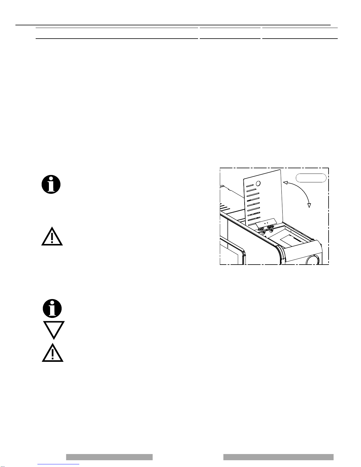
3.3 THE FEEDBOX
The feedbox is situated in the top part of the appliance. The load
capacity specified in the technical data can vary according to the
specific weight of the pellets.
Take special care when loading the tank of the screw feeder at
its base. Take care when topping up with fuel as the loading
area can get very hot.
Only pellets that comply with the specifications listed above
must be fed into the tank;
Never insert foreign objects into the tank. To access the feedbox
firstly remove the tank cover as illustrated in Figure 1.
Attention: when loading the pellets into the tank take care not to
drop any in the inner parts of the appliance, as this could cause
live flames inside the appliance. The manufacturer recommends
emptying the tank and vacuuming the screw feeder zone once a
month and during the summer period. The appliance is
designed to run on pellet fuel. Use of other combustible
materials in the tank and/or combustion chamber is strictly
prohibited.
4 - INSTALLATION
4.1 APPLIANCE LOCATION
Follow the general guidelines set out in paragraph 1.1 to the letter. Keep in mind that the flooring of the room in which
the appliance is to be installed must withstand the combined weight of the appliance and the pellets contained in the
tank.
CAUTION: The appliance must be installed in a room with adequate ventilation. The appliance must be positioned at
a minimum safe distance from walls and furnishings. If inflammable items are positioned near the appliance
(matchboarding, furniture, curtains, wall hangings, sofas, etc...), this gap must be increased considerably. The
recommended minimum distances are illustrated in Figure 1. If the flooring is made of wood or any other combustible
material, it is recommended to install a fireproof floor protector plate between the appliance and the floor. Installation
in the vicinity of heat-sensitive materials is only permitted if suitable insulating and fireproof protection is placed
between the object and the appliance (ref. Uni 10683). Failure to observe this instruction will immediately invalidate
the warranty.
The installer must issue a certificate of conformity for the installation which includes the design plans and the
following documents:
a) Report containing the type of materials utilised.
b) Project as defined in Article 5 of Ministerial Decree n°37 22 January 2008.
c) Drawing of the finished installation.
d) References to existing partial or previous declarations of conformity (e.g. electrical wiring).
e) Copy of the certificate of recognition of the professional technical qualifications.
Figura 1
Page 10
Installation, use and maintenance guide
These documents must, by law, be kept together with the
use and maintenance guide. The customer is responsible
for verifying, directly or indirectly, that the installation has
been carried out to perfection in accordance with relevant
regulations in force. Do not install the appliance in
unsuitable rooms such as bedrooms, bathrooms, garages
and/or lock-ups. It is forbidden to place the appliance in
environments with an explosive atmosphere.
ATTENTION , the stove is not simply a household
appliance: if the instructions set out in this booklet are not
followed and/or if installation of the appliance is not
executed perfectly and/or the provisions in force are not
strictly complied with, dangerous conditions could arise for
both objects and persons. It is the user’s responsibility to
verify the presence, in the room, of a vent necessary for
supplying oxygen to the generator.
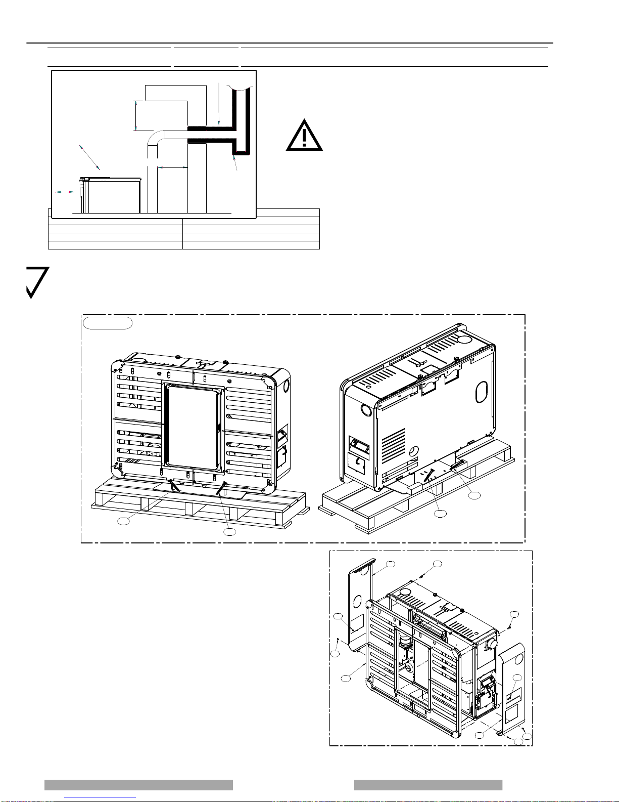
4.2 UNPACKING THE APPLIANCE
To unpack the appliance undo the screws C that fasten the base of the appliance to the pallet (Figure 1).
Figura 1
C
C
C
C
4.3 GLUING THE GLASS PANES TO THE FRONT PANEL
After unpacking the glass panes of the casing, disassemble the
front panel as described below. Prior to beginning any operation,
lay a soft sheet on the floor where you can place the front panel
after removing it from the appliance, in order to prevent damaging
the floor or scratching the paint on the panel.
• Undo screws A and slide out the left protective panel B
• Undo screws C and slide out the right protective panel D
• Undo the two screws E that fix the right side of the front panel
• Undo the two screws F that fix the left side of the front panel
• Remove the front panel by detaching it from the body of the
appliance.
• Lay the front panel on the sheet on the floor.
Legenda Key
Isolante termico Heat insulating material
200 – 450 mm se materiale combustibile 200 / 450 mm if combustible material
T ispezionabile Inspectable Tee element
Figura 1 Figure 1
200mmsematerialecombustibile
450mmsematerialecombustibile
ISOLANTETERMICO
200m
m
sem
ate
rialecom
bu
stibile
450mmsematerialecombustibile
Tispezionabile
Figura 1
A
A
B
CC
D
E
E
F
G

Page 10
lation, use and maintenance guide
SILICONEALTA
TEMPERATURA
AA
C
Figura 1
To glue the panes to the front panel, firstly apply silicone to the surface of the panel as illustrated in Figure 1. The silicone must be
suitable for high temperatures (>200°C). Attention: as highlighted in Detail C, do not apply silicone to the areas where the corners
of the glass cross over. If applied here the silicone could leak out and ruin the look of the product.
Position each glass pane by placing it in an inclined position and using the locators A indicated in Figure 1. When the edges of the
glass abut the locators A, delicately place the entire surface of the pane with the applied silicone and exert uniform pressure with
your hands over the whole surface, while making sure that the pane remains aligned in position. Repeat this procedure for all the
glass panes.
After checking that the panes are aligned with each other and with the front panel secure them in position by applying strips of
paper tape along the edges.
Wait at least 24h for the silicone to cure before handling the front panel. If the room temperature drops below 18°, wait 48 hours for
the silicone to cure completely.
4.4 CONNECTING THE APPLIANCE TO THE FLUE OUTLET
Connection of the appliance to the flue outlet must be carried out in
strict compliance with the instructions contained in this booklet (see
Chapter 9).
The appliance is fitted with the possibility for venting on three sides: top
left, side left and rear left (Figure 3).
Side or rear venting requires the use of a 90°elbow which is not supplied
with the appliance.
Once you have decided on the venting option that you wish to use, remove
the relevant precut shape. For this operation it is recommended to use a
blade for iron to prevent damaging the metal cover.
For instructions on how to install the smoke outlet in the wall, refer to the
technical drawings indicated in the “technical characteristics” in paragraph
2.
4.5 REMOUNTING THE FRONT PANEL
Once the appliance has been installed, the next step is to remount the front panel. Re-attach the front panel G to the body of the
appliance and lightly screw in the screws E (do not tighten). After checking that the front panel is aligned with the door (see the
alignment line in the drawing below) tighten the screws E. Complete the assembly of the heater.
ALLINEAMENTO
EG
G
E
E
ALLINEAMENTO = ALIGNEMENT
SUPERIORE
LATERALE
POSTERIORE
Figura 3
TOP
SIDE
REAR

Page 11
Installation, use and maintenance guide
4.6 HANDLE
Your appliance is supplied with a handle for opening and closing the firebox door to facilitate cleaning (see paragraph 8). The
handle is also designed to be used for regulating the ducting flow rate. When not in use, the handle can be stowed on the side of
the appliance if the hook provided is attached to the stove. (see Figure 4).
Figura 4
1
3
2
MANIGLIA
To mount the hook, remove the right side panel 1 of the heater (see paragraph 4.3), position the hook 2 in the hole and lock with
the nut 3. Replace the side panel 1.
HANDLE

Page 12
lation, use and maintenance guide
4.7 WALL MOUNT INSTALLATION
The appliance is supplied standard with a wall mount bracket.
To install the appliance on the wall firstly remove the left, right and front panels (see instructions in paragraph 4.3).
Remove the bracket A by undoing the two screws B which can be accessed by lifting the door C. For instructions on how to fasten
the bracket to the wall refer to the drawing in Figure 8.
Figura 7
Viti
B
Sportellino
C
Staffa
A
C
DETTAGLIO C
D
DETTAGLIO D
50858
Uscita Fumi
Posteriore Presa aria
comburente
C
a
n
a
l
i
z
z
a
z
i
o
n
e
Canalizzazione 213
369 458
86
97
364
O
80
O
80
O
80
600
332
STAFFA
A MURO
1040
LEGENDA KEY
Figura Figure
Viti Screws
Sportellino Door
Dettaglio Detail
Staffa Bracket
Canalizzazione Channelling
Uscita fumi posteriore Rear smoke outlet
Presa aria comburente Combustion air intake
Staffa a muro Wall bracket

Page 13
Installation, use and maintenance guide
14:30
WORK
3
2
5
48
1
76
11
13
12
14
14:30
WORK
Zona del display dove viene visualizzato il giorno
corrente (per esempio 3 pallini = mercoledì).
Indicatore livello
di ventilazione Zona del display
visualizzati fasi di funzionamento, ora....
dove vengono
"Themocomfort On "
ovvero connesso
Indicatore livello
di combustione
Hang the unit on the wall bracket A; once the appliance is suspended, push it firmly against the wall and tighten the screws B.
When carrying out this operation, take care to match up the support hooks (See details C and D in Figure 7).
Once you have completed this operation, remove the base by undoing the 4 screws that fix it to the structure of the appliance. It is
recommended to tighten the screws in the appliance once the base has been removed. Next assemble the front panel and the left
and right side panels.
ATTENTION: considering the weight of the appliance, it is recommended to use anchor bolts suitable for the type of
wall to which the appliance is mounted.
ATTENTION: it is necessary to ensure that the wall plaster and finish can resist a working temperature of 80 °C.
Given the working temperatures of the appliance it is normal for the wall to blacken, particularly if it is a light colour,
after a season of operation.
5 – DESCRIPTIONS OF CONTROLS
There are two main control pushbuttons marked with the ventilation symbol (2) and the symbol of the flame (1).The flame
pushbutton (1) sets the power of the appliance with 5 levels available which are activated as the 5 bars light up in sequence on the
display (7). The off cycle is activated when all power bars are turned off. The fan button (2) controls the ventilation of the appliance.
It is activated when the smoke, detected by the smoke probe, reaches a temperature over 60°C.
The fan can be set to any of 6 speed levels displayed by the 6 bars progressively coming on on the display (7): when the appliance
is on the ventilation cannot be switched off.
5.1 DESCRIPTION OF THE CONTROL PANEL AND BACK PANEL
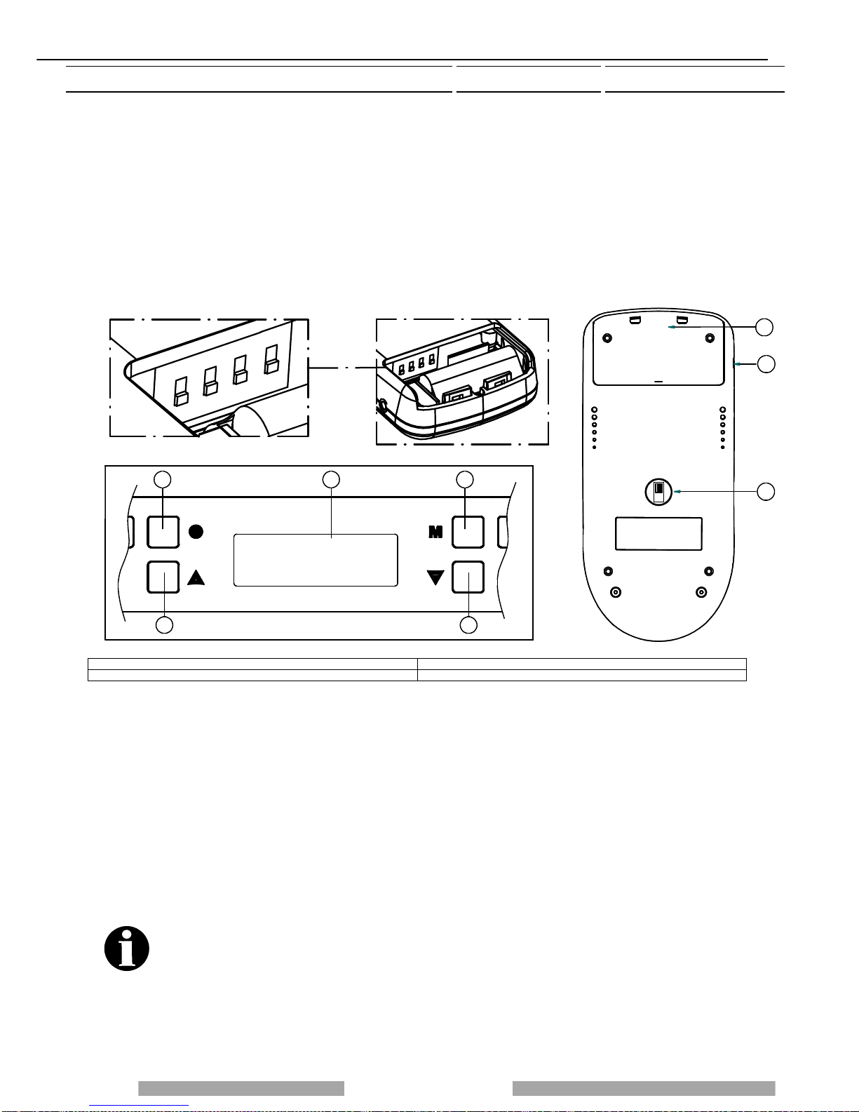
5.1.1 DESCRIPTION OF THE CONTROL PANEL
All controls and indicators are presented here below:
(1) Appliance on/off and flame adjustment button When you press
this button the appliance switches to START/WORK/ OFF
(appearing on the display 7). Press repeatedly to activate up to 5
bars on the display (7)
(2) Ventilation setting button Press this button to set the desired
level of ventilation: you can select up to a maximum of 6 speeds,
acknowledged by the corresponding bars lighting on the display (7).
One bar is always lit up even in OFF status.
(3) (4) Auxiliary setting buttons
Keys (3) and (4) are operating buttons necessary when on-off cycles
are programmed, for operative levels, clock setting, etc..
(5) Programming Enable / Disable / Chrono Reset buttons
(6) “MENU” selection button To access the main menu press the
button marked with 6. Press button 6 repeatedly to scroll the various
windows: date, programming setting,...
(7) Display
(8) Infrared remote control sensor
LEGENDA KEY
Zona del display dove viene visualizzato il giorno corrente (per esempio 3
pallini = mercoledì) Display area in which the current day is displayed (for example, 3 dots =
Wednesday)
Indicatore livello di ventilazione Ventilation level indicator
Zona del display dove vengono visualizzati fasi di funzionamento, ora… Display area in which the operation steps are displayed, time...
Indicatore livello di combustione Combustion level indicator
“Thermocomfort On” ovvero connesso "Thermocomfort On" i.e. connected
5.1.2 RH SIDE PANEL OF THE HEATER
A description of the functions of the buttons and LEDs on the rear panel:
(11) Main switch 0-1
(12) Electrical power outlet 220-240V 50 Hz.
(13) Overtemperature reset thermostat button cap
In the event of overtemperature this safety thermostat stops the loading of
pellets. To restart the appliance you need to wait until it cools down, then
verify the cause for the overheating, remove the cause, unscrew the
protective cap and press the button (13).
(14) Feed motor test indicator light When the pellet screw feeder is set
in motion the light must come on.
LEGENDA KEY
Riarmo Reset
Spia motoriduttore Ratio motor led

Page 14
lation, use and maintenance guide
DAYS
DATA MON
2
3
5
4
76
1
8
00 : 00
5.2 DAY AND TIME SETTING
The appliance must be energised and the rear
switch in position "1". The words START or WORK
or OFF could be present on the display (7). To set
the time and the day of the week carry out the
procedures described below. Press button (6) once;
the word DATA will appear on the display followed
by the words illustrated in the figure on the left. To
set the day press arrow button (3) and/or (4)
repeatedly until the desired day appears: (MON and
one dot for Monday -- TUE and two dots for Tuesday -- WED and 3 dots for Wednesday -- THU and 4 dots for Thursday -- FRI and
5 dots for Friday -- SAT and 6 dots for Saturday -- SUN and 7 dots for Sunday). Then confirm the day by pressing the key (1). The 2
digits representing the hours will start flashing in the display: it is possible to select the present hour using the arrow keys (3) and/or
(4), the selection must be confirmed by pressing key (1). The 2 digits indicating the minutes will start flashing: it is possible to select
the present minutes using the arrow keys(3) and/or (4), the selection must be confirmed by pressing the key (1). The day and time
setting is now completed.
5.3 ON/OFF PROGRAMMING
The generator must be energised and the rear switch in position "1". The words START or WORK or OFF could be present on the
display (7).
DAYS
CRONO MON
3
2
5
48
1
76
DAYS
CRONO MON
3
2
5
48
1
76
00: 00
ON 1
It is possible to carry out the weekly programming by setting up to 3 on/off cycles for each day from Monday to Sunday. To program
the heater press button (6) twice until the word CRONO appears followed by the words illustrated in the figure above on the left.
Now you can begin programming the first day of the week - Monday - by pressing button (1). Press the arrow button (3) and/or (4)
to choose another day to be programmed, to confirm the selection press button (1) again. The words ON1 will appear on the display
followed by 2 blinking digits indicating the hours (figure above right). Press button (3) and/or (4) to enter the hour of the first cycle
start time. To confirm the selection press the button (1). The 2 digits indicating the minutes will start flashing. Press button (3)
and/or (4)to enter the minutes of the first cycle start time. To confirm the selection press button(1).The first start up time for the
selected day has now been set. Then the inscription OFF1 will appear in the display and the two digits representing the hours will
turn on. When the (3) and/or (4) button is pressed the hour of the first off-cycle is entered. To confirm the selection press the button
(1). The 2 digits indicating the minutes will start flashing. By pressing the button (3) and/or
(4) the minutes for the first off-cycle will be entered. To confirm the selection press the button (1). This concludes the setting of the
first on-off cycle for the selected day. Later, it is possible to set the second on-off cycle (e.g. Monday) (shown with the display of
ON2 and OFF2) and the third Monday’s on-off cycle (shown with the display ON3 and OFF3). Next the display appears as
illustrated in the figure above on the left. Press the arrow button (3) and/or (4) to choose another day to be programmed, to confirm
the selection press button (1) again.
If you wish to copy all the on-off programs, for example the Monday settings, to the other days of the week, proceed as follows:
press button(6) until the word "CRONO" appears followed by the screen illustrated in the figure below on the left. Next press button
(2) and the display appears as illustrated in the figure below on the right: the program for Monday has been copied to Tuesday.
Press button (2) again to copy the program to Wednesday, Thursday ....
In the programming menu if you wish, for example, to edit the programming for Sunday press button (3) and/or (4) to go to Sunday
and then press button (1) . If the second on-off cycle is not required simply set the ON2 time as 00:00 and the OFF2 time as 00:00 .
DAYS
CRONO MON
348
2
576
1
DAYS
CRONO TUE
Copy
348
2
576
1

Page 15
Installation, use and maintenance guide
348
2
576
1
LEVEL 1
The programming procedure ends when you confirm the last data entered by pressing button (6) or when you exit the programming
menu. During the START or WORK or OFF phases press button (5) to enable / disable the programming (Enabled = CR.ON
appears momentarily on the display together with the fixed presence of the chrono symbol on the right of the display - see picture
below). Disabled: message CR.OFF temporarily displayed and, at the same time, the chrono symbol on the right side of the display
is not present (see figure below): this function is useful if you wish to disable the established weekly program setting. Moreover, you
can reset, or delete, all the programmings by holding down (in OFF or START or WORK phase) button (5) for approximately 8
seconds; the word "RESET CRONO" appears momentarily in order to indicate deletion of all the programmings previously set. With
the programming active, the operating conditions at the start-up (combustion power – ventilation speed) are the same as set-up
before the last off-cycle of the appliance: this is the case if the off-cycle has been done through the
programming and not through a manual action. Manual shut down can only be carried out with the programming disabled.
After shut down, by re-enabling the programming, at the next start up controlled by the programming the appliance will be set at the
first combustion power position and first ventilation speed.
In the event of a programmed cycle on always ensure that the brazier is clean and seated correctly in its
lodging: failure to clean the brazier can reduce and/or affect the life of the spark plug as it would be
subjected to high temperatures due to poor cooling. When the programming is enabled (CR.ON appears
momentarily together with the fixed presence of the chrono symbol on the bottom of the display) any
additional chronothermostats (see para. 7.2) are disabled.
WORK
14:30 14:30
WORK
Programmazione abilitata Programmazione disabilitata
Legenda Key
Programmazione abilitata / disabilitata Programming enabled / disabled
5.3.1 ON-OFF PROGRAMMING DISPLAYS
To view the programmings press button (6) 5 times until the words "Show Chrono" appear.
After a few seconds the display appears as illustrated in the figure below on the left. Press button (3) repeatedly to scroll the
programmings for all the days of the week (see figure below on the right) : press button (6) to exit.
Caution: the on-off programmings cannot be modified from the "SHOW CRONO" menu,
this menu is used only for viewing the programs that have been entered and/or edited through the "CRONO menu".
5.4 OPERATING LEVEL SETTING
The appliance must be energised and the rear switch in position
"1".
The words START or WORK or OFF could be present on the
display (7).
Your appliance is delivered with an excellent program installed
that favours combustion yield; the program is called
LEVEL 1. If you are using pellets with an out-of-standard
incidence of residues after combustion in the brazier, alternative
levels may be selected:
DAYS 10:45
MON
348
2
5 7 6
1
DAYS 10:45
MON
348
2
576
1
ON 1 11:15
OFF 1 13:45

Page 16
lation, use and maintenance guide
LEVEL 2: this program increases the smoke suction unit speed acceleration (program Level 2 increases air delivery to the burner
which promotes the combustion of tightly compacted pellets: this program reduces combustion efficiency).
LEVEL 0: when using too long pellets and/or flue outlets with very high vacuum, over 2 Pascal. When operating at LEVEL 0 the
burner becomes dirty very easily. The pellet consumption value is not affected by the operating level settings. Select the required
level by acting as follows:
press button (6) three times until the word LEVEL appears on the display after which the level set will appear (LEVEL 1 or LEVEL 2
or LEVEL 0). In order to change the operating level as key (3) is kept pressed, press the key (4). By holding down button (3) and
pressing button (4) repeatedly the level changes in the following sequence: LEVEL 2... ...LEVEL 0 ... LEVEL 1.
If the change is made while the appliance is running the difference in the flame will be apparent. It is
mandatory to pay particular care when selecting the most appropriate operating cycle for your
installation. After the selection of the operating cycle a thorough cleaning of the brazier is mandatory.
For the entire procedure to be confirmed and to move back to the appliance status display, key (6) must
be repeatedly pressed.
6 – USE OF THE APPLIANCE
Your appliance has obtained the CE marking and has been made to run for 1 hour to check that it functions correctly. It has also
undergone numerous tests as detailed in the test check sheet supplied with the generator. The product must not be used by
children, by persons with physical or mental impairments, by persons who are not familiar with the instructions for use and
maintenance of the product (the instructions are found in this booklet). CAUTION: Before each use make sure that the burner is
clean and positioned correctly in its lodging, check that the ash pans are clean and shut tight and check that the firebox door is
locked. WARNING: the door must always remain shut tight when the heater is operating. It is strictly forbidden to open the door
while the appliance is in operation. While the appliance is in operation the smoke exhaust pipes and the appliance itself can reach
extremely high temperatures: do not touch them! Do not expose your body to hot air for long, do not overheat the room in which the
appliance is installed, as these actions could cause health problems. Do not expose plants or animals directly to the hot air flow as
this could have noxious effects on them. It is strictly forbidden to use any type of fuel (liquid, solid...) to light the appliance : the
appliance must light up automatically as designed and described in this installation, use and maintenance booklet; in this regard, it
is strictly prohibited to pour pellets (or other material) directly into the brazier. Do not place non-heat resistant or inflammable or
combustible objects in the vicinity of the appliance: keep them at a suitable distance. Do not place wet clothing to dry on the
appliance.
When using a clothes horse, keep at a suitable distance. It is strictly prohibited to disconnect the appliance from the electrical
power mains while it is in operation.
6.1 SWITCHING ON THE APPLIANCE
Before using the appliance check that all the movable parts are in place; also remove any labels and stickers from the glass to
avoid having permanent traces remain on the surfaces. Always ensure that the brazier is clean and seated correctly in its lodging
(see para. 8).
Turn the switch installed on the back of the appliance to position "1" (= ON). Press button (1) to start the start up phase.When key
(1) is repeatedly pressed, the desired combustion level can be set and it will be active at the end of the ignition stage. The electrical
heater will start to overheat and after a few minutes the first lot of pellets will start dropping into the brazier. This occurs because the
screw feeder has to fill up because it is completely empty. The first time the appliance is started up the start up phase will have to
be carried out twice for this very reason.
CAUTION: The start up phase (the word START appearing on the display) continues until the word
START .remains lit.Once this phase has ended the word WORK appears on the display. The fan will
begin operating as soon as the combustion smoke reaches a suitable temperature. During the work
stage it is then possible to adjust combustion and the ventilation:
The combustion can be adjusted by 5 bars through button (1)), the ventilation setting can be set on 6 levels indicated by the
sequential lighting up of the corresponding bars on the display (through button (2)).
To turn the appliance on it is necessary for the inscription OFF to be present on the display: if it is not present, the key
(6) must be repeatedly pressed until the inscription OFFappears.

Page 17
Installation, use and maintenance guide
8R
9R
10R
3R
2R 4R 1R
6R
7R 5R
11R
12R
13R
6.2 COMBUSTION AND VENTILATION ADJUSTMENTS
The heating capacity is adjusted by pressing key (1) or on the remote control provided. Act on this command to adjust the quantity
of pellets fed to the firebox. Maximum combustion power is achieved when all 5 leds are lit.
Caution: the room fan starts up as soon as the temperature of the combustion smoke reaches a suitable threshold. The
fan setting is expressed visually by means of 6 different positions represented by 6 bars: press button (2) repeatedly to
regulate it. A slight vibration of the appliance is quite normal when it is running. One bar is always present on the display
even in OFF status.
6.3 INFRARED REMOTE CONTROL
A practical infrared remote control is supplied with the heater: adjust the ventilation level by means of the left button, whereas use
the right button to start the appliance, to adjust the power and combustion level and to switch off the appliance. If the appliance is
supplied with a white radio control (optional) the infrared control only works when the MANUAL setting is set on the white handheld
radio control.
6.4 OPERATION OF THE WHITE HANDHELD RADIO CONTROL THERMOCOMFORT (OPTIONAL)
INTRODUCTION
The Thermocomfort handheld radio control is the instrument that allows you to optimise both consumption and
functions. Keep in mind that radio wave transmissions can be affected by the surrounding environment: the presence
of thick walls can reduce the transmission that normally extends to 6-7 metres.
CAUTION: to guarantee optimal data transmission it is advisable to always place the radio control in its support in
a vertical position.
The following operations must be carried out the first time the appliance is started up:
• Turn the switch (11R) to ON (see drawing below)
• Connect the radio control to the mains power supply by means of the supplied battery charger. The radio control
must be recharged for at least 5 days, as the rechargeable batteries could be partially or completely empty.
Repeat the same procedure every time the radio control batteries discharge.
The appliance must be energised and the rear switch turned to position "1".
CAUTION: the Thermocomfort function is disabled when the remote control is OFF. To enable it, in the START,
WORK, OFF phases, repeatedly press button (6) on the appliance's control panel until the word
"THERMOCOMFORT" appears on the display (7) followed by the words Thermocomfort Off". To activate the
Thermocomfort function simply press the button (3) on the appliance's control panel: " Thermocomfort On". To
return to the original operating function simply press the button (6) again on the appliance's control panel. At the
end of the winter season, in order to preserve the life of the batteries, it is mandatory to recharge the batteries
and switch off the radio control completely by means of the switch located on the back (11R). The batteries are
guaranteed for 6 months. When the batteries are exhausted dispose of them safely. It is normal for the
temperature sensor to detect temperatures which are slightly different to the real ones: variations caused by the
environment in which the radio control is positioned and by the tolerance of the thermostat.
6.4.1 INDICATORS OF THE HANDHELD RADIO CONTROL
(1R) Flame selection button
(2R) Ventilation selection button
(3R) (4R) Auxiliary buttons
(5R) “Room temperature detected by the radio control's sensor” indicator
(6R) "Ventilation" indicator
(7R) “Combustion” indicator
(8R) “Room temperature setting” indicator: this is the room temperature
that you wish to reach by means of buttons 3R and 4R.
(9R) Area of the display where the operating program is displayed
(10R) Battery charge level
(11R) Switch 0-1 radio control power
(12R) Battery charger connection
(13R) Code selector and batteries compartment cover

Page 18
lation, use and maintenance guide
The Thermocomfort radio control can be used with 4 different operating programs:
• Manual (MANUAL appears in area (9R) of the display).
• Automatic 5 (AUTO 5 appears in area (9R) of the display).
• Automatic 3 (AUTO 3 appears in area (9R) of the display).
• Economy (ECONOMY appears in area (9R) of the display).
To change the operating program turn the switch (11R) to "1". Press and hold down button (3R) until the set program begins to blink
on the display (9R). Now release button (3R) and press button (3R) and/or (4R) repeatedly until you select the desired operating
program.
MANUAL program (the "Thermocomfort ON" symbol blinks on the display of the appliance).In the MANUAL program the room
temperature thermostat is disabled. Press button (1R) and the flame symbol begins to blink. Press button (3R) to decrease the
combustion level by lighting up the bars sequentially, vice versa press button (4R)
to increase the combustion level. The combustion level changes every time buttons (3R) and (4R) are pressed. Press button (2R)
and the ventilation symbol blinks. Press button (3R) to decrease the combustion level, vice versa press button (4R) to increase the
combustion level. The ventilation level changes every time buttons (3R) and (4R) are pressed. Caution: it is possible that, due to
radio interference or sending commands too close together, the changes will not be implemented. With this program you can also
use the infrared control supplied. It is normal that in the manual cycle the ventilation is often set at the maximum speed in order to
cool the appliance body more effectively.
AUTO 5 program (the "Thermocomfort ON" symbol is steady on the display of the appliance) In program AUTO 5 the room
temperature thermostat is enabled. The radio control adjusts the ventilation and the combustion automatically in relation to the
target room temperature set in display area (8R). The desired room temperature
appears in area (8R). You can vary the desired room temperature by simply pressing button (3R) and/or (4R) (variation indicated in
area (8R)). The remote control will set the maximum combustion and ventilation levels and modulate them both as the room
temperature (5R) approaches the target temperature (8R). When the target temperature (8R) in the room (5R) is reached, the
combustion level will stabilise on a bar as will the ventilation level.
Caution: it is possible that, due to radio interference, the commands sent to the generator will not be implemented. When using this
program the infrared remote control cannot be used. Caution: the power and the ventilation depend on the preset value, if the
required temperature is too high or not reachable the appliance could operate at maximum power for long periods of time.
AUTO 3 program (the "Thermocomfort ON" symbol is steady on the display of the appliance) In program AUTO 3 the room
temperature thermostat is enabled. The remote control adjusts the ventilation and combustion automatically in relation to the target
room temperature set in display area (8R). The desired room temperature is displayed in area (8R).
You can vary the desired room temperature by simply pressing button (3R) and/or (4R) (variation indicated in area (8R)). The
remote control will set the combustion power at level 3 and the ventilation at level 4 and modulate them both as the room
temperature (5R) approaches the target temperature (8R). When the target temperature (8R) in the room (5R) is reached, the
combustion level will stabilise on a bar as will the ventilation level. Caution: it is possible that, due to radio interference, the
commands sent to the appliance will not be implemented. When using this program the infrared remote control cannot be used.
Caution: the power and the ventilation depend on the preset value, if the required temperature is too high or not reachable the
appliance could operate at maximum power for long periods of time.
ECONOMY program (the "Thermocomfort On" symbol is steady on the display of the appliance) In the ECONOMY program the
appliance always operates at the minimum combustion level and the minimum ventilation level. When using this program the
infrared remote control cannot be used.
CAUTION: THE APPLIANCE MUST ALWAYS BE STARTED UP AND SHUT DOWN FROM THE CONTROL PANEL
OR THROUGH PROGRAMMING.
6.4.2 TRANSMISSION CODES SETTINGS
The appliance must be energised and the rear switch in position "1". The words START or WORK or OFF could be present on the
display (7).
Page 19
Installation, use and maintenance guide
If there are several appliances installed in rooms closely to each other it may be necessary to set different transmission codes as
this type of interference deactivates operation of the optional Thermocomfort radio control. To change the transmission codes
proceed as follows:
-Disable the Thermocomfort function. To disable it, in the START, WORK, OFF phases, repeatedly press button (6) on the
appliance's control panel until the word "THERMOCOMFORT" appears on the display (7) followed by the words Thermocomfort
On". To deactivate the Thermocomfort function simply press the button (3) : "Thermocomfort Off". To return to the original operating
function simply press the button (6) again.
-Switch off the Thermocomfort radio control by pressing the button (11R) on the device.
-To change the transmission codes, open the cover (13R) and act as indicated in the figure below.
-Next switch on the radio control by pressing the button (11R).
-Activate the Thermocomfort function. To enable it, in the START, WORK, OFF phases, repeatedly press button (6) on the
appliance's control panel until the word "THERMOCOMFORT" appears on the display (7) followed by the words Thermocomfort
Off". To activate the Thermocomfort function simply press the button (3): "Thermocomfort On". To return to the original operating
function simply press the button (6) again. The radio control may still not function even after having changed the transmission
codes. If this occurs change the codes once again using the procedure described above.
LEGENDA KEY
Selettore codici per radiocomando palmare gestito via onde radio Code selector for handheld radio control controlled by radio waves
6.4.3 CARE AND MAINTENANCE OF THE RADIO CONTROL
The radio control has been designed and produced to the strictest standards and must be handled with great care. If you observe
the guidelines set out below, the radio control will provide a long trouble-free performance:
• Protect the radio control against humidity! Precipitation, humidity and liquids corrode the electronic circuits. If the radio control is
wet, disconnect it immediately from a power source, remove the battery, open it and allow it to dry at room temperature.
• Do not use or store the radio control in dusty or dirty environments. The dust/dirt could damage the movable parts of the radio
control.
• Do not store the radio control in very hot environments. High temperatures could shorten the life of the electronic devices, damage
the batteries and deform or even melt plastic parts. Do not store the radio control in cold environments. When it heats up (when it
returns to normal operating temperature), humidity could form inside it and damage the electronic circuits.
• Do not drop the radio control, do not hit or bump it and do not shake it. Actions such as these could damage the internal circuits of
the device.
• Do not use corrosive chemical substances, caustic solutions or detergents to clean the radio control.
All the above guidelines apply to the radio control, the battery, the battery charger, and all the accessories. The parts
subject to wear (such as batteries, keypads, lodging compartments, small compartment parts) are guaranteed for 6
months from the purchase date. The guarantee does not apply if the defect is caused by non-conforming use and/or
if the instructions and guidelines described above are not observed to the letter. Devices or parts returned for
replacement become the property of Thermorossi S.p.A. The presence of any irregular black-blue lines on the
display, also present when de-energised and/or battery flat or missing, indicate that the glass screen of the display is
damaged following a fall or impact: in this case the breakage is not covered by the guarantee.
SELETTORE CODICI PER RADIOCOMANDO
P
A
L
M
A
R
E
G
E
S
T
I
T
O
V
I
A
O
N
D
E
R
A
D
I
O
ON
1234
3
1
ON
24
THERMOCOMFORT
3
5
4
7 6
Thermocomfort
On
11R
12R
13R
Table of contents
Other THERMOROSSI Pellet Stove manuals


Popular Pellet Stove manuals by other brands


Quadra-Fire
Quadra-Fire SANTAFE-MBK installation manual

Ravelli
Ravelli Whisper 7 Use and maintenance manual

United States Stove
United States Stove Ashley Heritage 5700 owner's manual

Masport
Masport STM00739 Owners manual instructions

Napoleon
Napoleon Auburn NPS40 Installation and operating insctructions

Olsberg
Olsberg Levana manual


