Theta Digital Generation VIII Series 3 User manual
THETA DIGITAL
Generation VIII Series 3
Owner’s Manual
V 2.00
Digital Done Right
™

ii
PREFACE CONGRATULATIONS
You have just acquired the most advanced component for the processing and conversion of digital to analog
signals to have been developed.
IMPORTANT
Save all packaging in a dry place away from fire hazards. Your Generation VIII is a precision electronic
instrument and should be properly packaged any time shipment is made. In the unlikely event that you have to
return your Generation VIII to the factory for service, or if you send it to us for updating, the original packaging
will best protect the unit from shipping damage.
In order to achieve the fullest flexibility and enjoyment from your Generation VIII, we at Theta recommend that
you read this manual in full before connecting the unit to your audio/video system.
WARNING
United Stated law prohibits disposition of these commodities to Libya, Laos, North Korea, Cambodia or Cuba
unless otherwise authorized by the United States.
NOTE:
This equipment has been tested and found to comply with the limits for a Class B digital device, pursuant to Part
15 of the FCC rules. These limits are designed to provide reasonable protection against harmful interference in
a residential installation. This equipment generates, uses and can radiate radio frequency energy and, if not
installed and used in accordance with the instructions, may cause harmful interference to radio
communications. However, there is no guarantee that interference will not occur in a particular installation. If
this equipment does cause harmful interference to radio and television reception, which can be determined by
turning the equipment off and on, the user is encouraged to try to correct the interference by one or more of the
following measures:
* Reorient or relocate the receiving antenna.
* Increase the separation between equipment and receiver.
* Connect the receiver into an outlet on a circuit different from that to which the Generation VIII is connected.
Acknowledgments
©2003-2011 Theta Digital. All rights reserved.
This manual is also available for download as a PDF file at Theta Digital’s website: http://www.thetadigital.com
No part of this publication may be reproduced or transmitted in any form or by any means, electronic or
mechanical, for any purpose, without the express written permission of Theta Digital.
iii
The lightning flash with arrowhead symbol, within an equilateral
triangle, is intended to alert the user to the presence of uninsulated
“dangerous voltage” within the product’s enclosure that may be of
significant magnitude to constitute a risk of electric shock to persons.
The exclamation point within an equilateral triangle is intended to alert
the user to the presence of important operating and maintenance
(servicing) instructions in the literature accompanying the product.
WARNING TO REDUCE THE RISK OF FIRE OR ELECTRIC SHOCK,
DO NOT EXPOSE THIS PRODUCT TO RAIN OR MOISTURE
CAUTION: TO PREVENT ELECTRIC SHOCK, DO NOT USE THE (POLARIZED) PLUG WITH AN
EXTENSION CORD, RECEPTACLE OR OTHER OUTLET UNLESS THE BLADES CAN BE FULLY
INSERTED TO PREVENT BLADE EXPOSURE.

iv
Generation VIII Identification Record
This information is for your records and for future identification of the Generation VIII. Please take a moment
to fill out all pertinent data now, and as upgrades and/or options are installed. Whenever upgrades,
inquiries, service, repair and/or changes are requested, the serial number will be required.
SERIALNUMBER
DATE PURCHASED
DEALER’SNAME
DEALER’S ADDRESS/PHONE
INSTALLED CARDS/OPTIONS/UPGRADES
(Dateofinstallation)
(Dateofinstallation)
(Dateofinstallation)
(Dateofinstallation)
(Dateofinstallation)
(Dateofinstallation)

v
SAFETY PRECAUTIONS
Please carefully read each item of the operating instructions and safety precautions before using this
product. Use extra care to follow the warnings written on the product itself and/or in the operating
instructions. Keep the operating instructions and safety precautions for future reference.
CAUTION: TO REDUCE THE RISK OF ELECTRICAL SHOCK, DO NOT REMOVE ANY OF THE COVER
PANELS.
NO USER-SERVICEABLE PARTS INSIDE. REFER ALL SERVICING TO QUALIFIED SERVICE
PERSONNEL ONLY.
TO PREVENT FIRE OR SHOCK HAZARD, DO NOT ALLOW LIQUIDS TO SPILL OR OBJECTS TO FALL
INTO ANY OPENINGS OF THE PRODUCT.
THIS UNIT IS SUPPLIED WITH A 3 PIN GROUNDED AC PLUG. ALWAYS INSERT THE AC PLUG INTO
A GROUNDED OUTLET. DO NOT REMOVE THE GROUND PIN OR DISABLE THE GROUND FOR ANY
PURPOSE.
BEFORE MAKING ANY CONNECTIONS TO THE GENERATION VIII, FIRST TURN OFF THE POWER
AND THEN DISCONNECT THE AC POWER CORD.
WHEN INSTALLING THE GENERATION VIII IN YOUR SYSTEM, MAKE CERTAIN TO ALLOW A
MINIMUM OF 3 INCHS OF VENTILATION ON EACH SIDE OF THE UNIT. ALSO ALLOW AT LEAST 3½
INCHS OF VENTILATION SPACE ABOVE THE UNIT. IMPROPER VENTILATION OF THE UNIT MAY
CAUSE OVERHEATING, WHICH MAY DAMAGE THE UNIT AND CAUSE A FIRE. PLACE THE UNIT ON
A SOLID SURFACE ONLY. I.E. NOT ON CARPET, ETC.
DO NOT PLACE THE GENERATION VIII NEAR HEAT SOURCES SUCH AS DIRECT SUNLIGHT,
STOVES, HEAT REGISTERS, RADIATORS OR OTHER HEAT PRODUCING EQUIPMENT.
TO PREVENT DAMAGE TO THE ANALOG OUTPUT CIRCUITRY, BE CERTAIN NOT TO SHORT THE
OUTPUT SIGNAL PIN(S) TO GROUND. ENSURE THAT YOUR AUDIO OUTPUT CABLES DO NOT
HAVE ANY INTERNAL SHORTS BEFORE CONNECTING THEM TO THE GENERATION VIII.
IF REPLACEMENT OF THE AC LINE FUSE BECOMES NECESSARY, REPLACE ONLY WITH SAME
VALUE AND TYPE OF FUSE. NEVER BYPASS THE FUSE.
IF THE AC CORD BECOMES DAMAGED, DO NOT USE IT. IMMEDIATELY REPLACE IT WITH A NEW
ONE OF THE SAME OR BETTER RATING.
AFTER MARKET and THIRD PARTY MODIFICATIONS
Please note that any after market and/or third party modifications will void the warranty. In the case of
changing the feet on a unit, in order to prevent any damage (which will also not be covered under warranty),
please verify that the screws being used to secure non Generation VIII feet do not screw any deeper into the
chassis than the original ones. The original screw is 1/4-20 by 3/8 and goes into the chassis 1/4 inch MAX.

vi
Table of Contents
PREFACE...........................................................................................................................................................ii
WARNING......................................................................................................................................................iii
Generation VIII Identification Record.............................................................................................................iv
SAFETY PRECAUTIONS...............................................................................................................................v
List of Figures................................................................................................................................................ vii
List of Tables................................................................................................................................................. vii
INTRODUCTION................................................................................................................................................1
Getting to know your Generation VIII..............................................................................................................1
IMPORTANT NOTICE....................................................................................................................................2
Reference Manual Conventions......................................................................................................................2
Glossary of Terms and Abbreviations.............................................................................................................3
Generation VIII Block Diagram .......................................................................................................................4
Front Panel Layout..........................................................................................................................................5
Rear Panel Layout ..........................................................................................................................................6
Menu Maps .....................................................................................................................................................7
Setup Menu Pages......................................................................................................................................7
Remote Control...............................................................................................................................................8
Introduction to the User interface....................................................................................................................9
OPERATIONS..................................................................................................................................................10
Input Select Buttons......................................................................................................................................10
Changing Inputs ........................................................................................................................................10
SETUP ..........................................................................................................................................................11
Jack and Input Names...............................................................................................................................11
Clocking.....................................................................................................................................................12
Unity Gain..................................................................................................................................................12
Input Offset Level ......................................................................................................................................12
Burn In.......................................................................................................................................................13
Remote Triggering.....................................................................................................................................13
RS232........................................................................................................................................................14
IR Source...................................................................................................................................................15
Using Generation VIII as an External DAC...............................................................................................15
Screensaver ..............................................................................................................................................16
Initial Volume Level ...................................................................................................................................16
Serial Number/Software Versions.............................................................................................................17
BALANCE Function.......................................................................................................................................17
APPENDIXES...................................................................................................................................................18
Appendix A Troubleshooting Guide ........................................................................................................19
Appendix B Wiring Diagrams..................................................................................................................20
Appendix C Upgrading/Re-installing Generation VIII Software...............................................................22
Appendix D Remote Extender Jack Technical Description and Protocol...............................................23
Appendix E RS232 Protocol....................................................................................................................24
RS232 Hardware Connections..................................................................................................................24
Appendix F Specifications.......................................................................................................................30
Warranty Information........................................................................................................................................32

vii
List of Figures
Figure 1 - Generation VIII Block Diagram ..........................................................................................................4
Figure 2 - Front Panel Layout.............................................................................................................................5
Figure 3 - Rear Panel Layout .............................................................................................................................6
Figure 4 - Setup Menu Pages.............................................................................................................................7
Figure 5 - Remote Control..................................................................................................................................8
Figure 6 - Front Panel Display of the INPUT SELECT page............................................................................10
Figure 7 - Front Panel Display of the INPUT SELECT page when Fixed Volume Controls are installed........10
Figure 8 - Front Panel Display of the Jack Map and Input Name SETUP menu.............................................11
Figure 9 - Front Panel Display of the Input Clocking SETUP menu.................................................................12
Figure 10 - Front Panel Display of the Unity Gain SETUP menu.....................................................................12
Figure 11 - Front Panel Display of the Offset Level SETUP menu..................................................................13
Figure 12 - Front Panel Display of the Burn In Signal SETUP menu...............................................................13
Figure 13 - Front Panel Display of the Remote Trigger SETUP menu ............................................................13
Figure 14 - Front Panel Display of the RS 232 SETUP menu .........................................................................14
Figure 15 - Front Panel Display of the IR Source SETUP menu .....................................................................15
Figure 16 - Front Panel Display of the Ext Vol SETUP menu..........................................................................15
Figure 17 - Front Panel Display of the SETUP page 8 – Screensaver............................................................16
Figure 18 - Front Panel Display of the Initial Volume SETUP menu................................................................16
Figure 19 - Front Panel Display of the Info menu.............................................................................................17
Figure 20 - Front Panel Display of the Balance Menu......................................................................................17
Figure 21 - Examples of Typical In and Out Connections................................................................................20
Figure 22 - Example of Connections to/from a Casablanca II/III Digital Out Card...........................................21
List of Tables
Table 1 - Glossary of Terms and Abbreviations.................................................................................................3
Table 2 – Display Jack Name Abbreviations & Definitions ..............................................................................11
Table 3 – Troubleshooting Guide.....................................................................................................................19

1
INTRODUCTION
Welcome to a new world of possibilities. Generation VIII is by far the most advanced digital to analog
converter available today. It offers the advantages of Theta’s legendary mastery in digital signal processing
and sound quality unapproachable by any other equipment.
Getting to know your Generation VIII
Despite the Generation VIII’s great technical sophistication, we believe in making it as easy as possible for
you to use. We think you’ll enjoy the intuitive way the Generation VIII works. Rather than offer a frustrating
bewilderment of little used functions in constant view, vying for your attention, Generation VIII is structured
systematically by function.
This Generation VIII has been put through a rigorous and unique testing procedure that insures that it will
last for many years with minimal service requirements. This procedure includes the following:
• All assembled circuit boards are given a thorough visual inspection and are then tested in a bench-
reference Generation VIII.
• The tested, assembled circuit boards are then installed in a new Generation VIII and the whole unit is
tested for every function and parameter.
• The unit is put on a burn-in torture rack for 100 hours to test for any possible component failures.
• The Generation VIII is tested on an audio analyzer for all pertinent parameters.
• The Generation VIII is put through a final bench test wherein every possible feature, mode and
parameter is checked.
• The unit has all remaining chassis components installed and then undergoes a complete visual
inspection, which assures that all Generation VIII’s meet visual specifications.
• The unit is then put through a critical listening test.
Burn In Time
This unit has a break in period of about 1 week during which continuous improvement in sound quality will be
observed. It is recommended that music or the internal burn-in signal be played continuously through the
unit during this time to expedite the break in period.

2
IMPORTANT NOTICE
I. Due to the computer-based circuitry used in Theta products, it is imperative that the Generation VIII
be connected to a ground via its three wire AC power cord. It is important that the AC power outlet
which the Generation VIII is plugged into, is actually grounded. Failure to do so will severely
compromise the performance, reliability and safety of use of the Generation VIII.
II. It is also important to prevent discharge of static electricity when connecting other components and
cables to the Generation VIII. When connecting cables, simply place one hand on top of the
Generation VIII and then grasp the metal “barrel” of the cable with the other hand and plug (unplug)
the cable into (from) the appropriate jack on the Generation VIII.
III. The Generation VIII, as with all electronic equipment, is susceptible to static discharges. Resetting
the unit may be required if anomalies occur after receiving a static discharge. In this case, put the
unit in standby and turn off the rear panel power switch for 2 minutes, and then turn it on again.
IV. Ventilation is an important issue when placing the Generation VIII in a system. Make certain that the
Generation VIII is placed in a well-ventilated area or rack unit. There must be a clear path for cool
air to get into the unit, and for heat to escape.
V. Please take note that some powerline conditioners defeat the AC power ground on their outlets. If
the intention is to plug the Generation VIII into a line conditioner, check with your dealer to make
certain that the particular conditioner that is intended for use DOES NOT DEFEAT THE AC
GROUND on its AC outlets.
VI. DO NOT remove any cover panels from the Generation VIII, as there are no user serviceable
components inside. Refer updating and servicing to Theta qualified service personnel only.
VII. Should the Generation VIII need to be reset, it must be put in standby first via the front panel power
button. Then the rear panel power switch is to be turned off for at least 2 minutes.
VIII. The Generation VIII can be susceptible to excessive RF. End caps in all unused inputs will improve
the sound quality and may reduce the susceptibility to RF induced anomalies.
Reference Manual Conventions
For clarity purposes, references to buttons, LED’s and display parameters will be shown in bold capital
letters.

3
Glossary of Terms and Abbreviations
TERM DEFINITION
AES/EBU (Audio Engineering Society) / (European
Broadcasters Union) A three wire balanced digital audio standard. This interface uses a 3-pin
XLR type connector and allows for data communication between digital
audio equipment.
Analog-to-Digital Converter A device that converts analog signals into a digital format. Once
encoded, all audio is stored or processed as a series of numbers rather
than as the audio itself.
Balanced Audio Signals Signals that are carried on three-conductor cables, with two of the
conductors carrying the same signal 180° out of phase and the third as
ground. Balanced connections usually cost more than unbalanced
connections, but are less susceptible to picking up hum and prevent
interference with low-level signals.
DAC Digital to Analog converter
dB Decibel, a relative unit of loudness.
Digital-to-Analog Converter (DAC) A device that converts digital signals into an analog format.
DSP Digital Signal Processor (Processing)
Hz (Hertz) A unit of frequency.
IR Infrared. A wireless method of data transmission.
mS Millisecond, or 1/1000 of a second.
Oversampling The process of taking more samples than is required in order to more
accurately reconstruct a digitized signal for playback in the analog
domain.
Sampling Rate The rate at which an analog (real world) signal is converted into digital
numeric values.
Single-Ended or SE, aka Unbalanced Audio Signals Signals that are carried on two-conductor cables, one “hot”, or signal, and
one ground.
S/PDIF Interface (Sony/Phillips Digital Interface
format) A digital audio interconnection standard, developed jointly by Sony and
Phillips.
TRS Tip, Ring, Sleeve. Names of the 3 connecting elements of a stereo phono
jack or plug.
VFD Vacuum Florescent Display
Table 1 - Glossary of Terms and Abbreviations
4
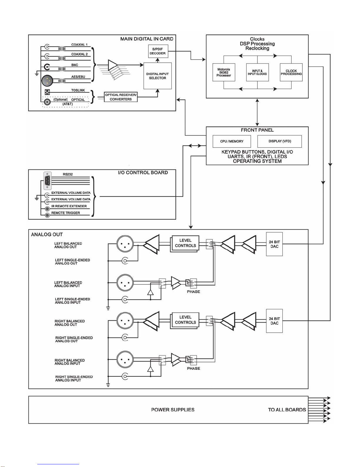
Generation VIII Block Diagram
Figure 1 - Generation VIII Block Diagram
5
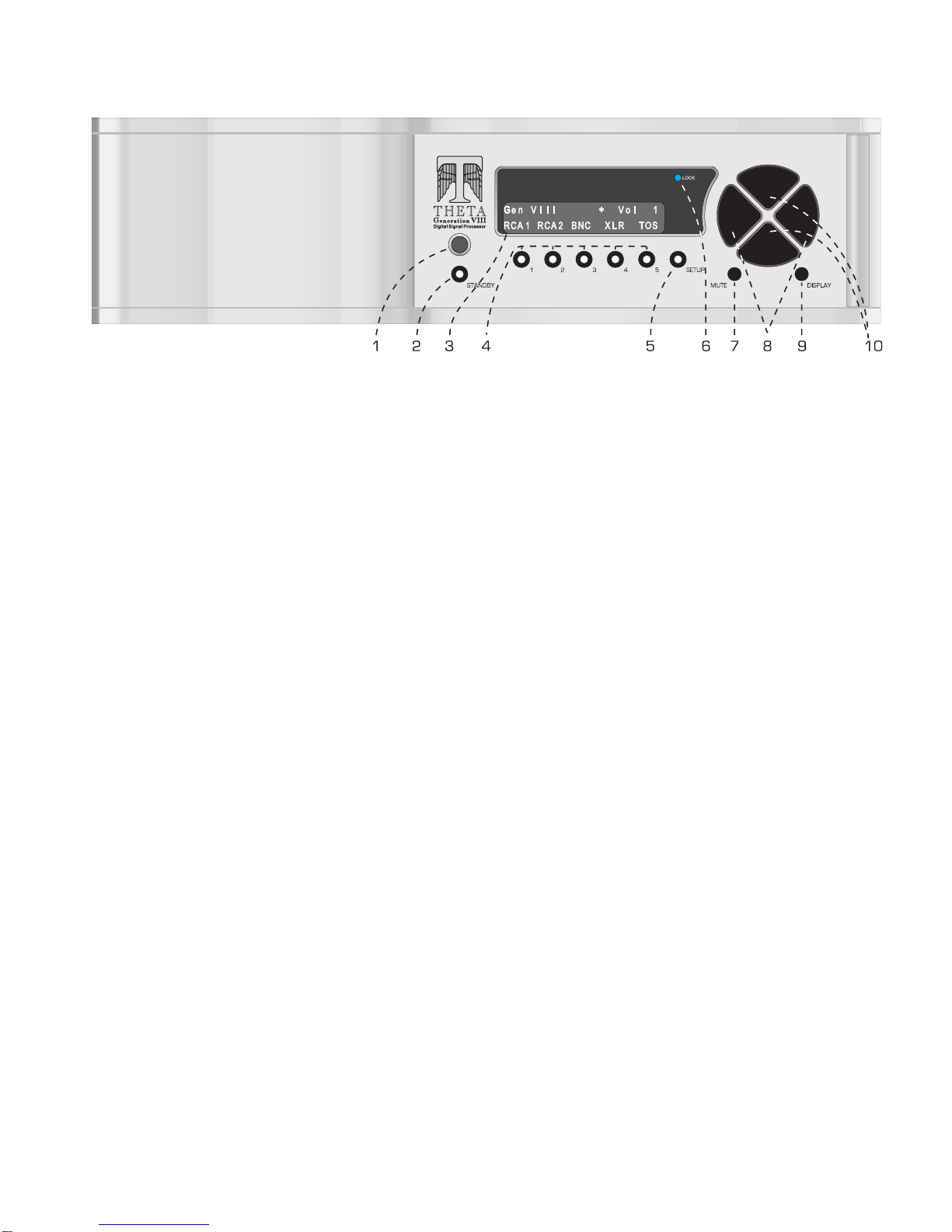
Front Panel Layout
Figure 2 - Front Panel Layout
1. Remote IR receiver.
2. STANDBY button/LED. After the rear panel MAIN POWER switch is turned on, press the front panel STANDBY button to exit
the standby mode. The Generation VIII will quickly initialize. The VFD will default to the last selected INPUT. Pressing
STANDBY again will place the Generation VIII into standby mode and the LED in the front panel STANDBY button will light.
Each time the Generation VIII is put into standby, the VFD will “exercise” itself for 10 seconds by illuminating all pixels. (This
will enhance the lifetime of the VFD).
3. 24 character by 2 row Vacuum Florescent Display (VFD).
4. Buttons 1through 5. Used to select a desired INPUT, or parameter to change in the SETUP menus. The LED in the button
lights when the button is pressed. These buttons are referred to as the INPUT SELECT buttons.
5. SETUP button. Used to access the SETUP menus, for setting all user parameters.
6. LOCK light. Lights when a valid digital signal is detected on the currently selected input.
7. MUTE button. Mutes/unmutes all audio outputs. Not active when optional fixed volume cards are installed.
8. LEVEL LEFT and RIGHT buttons. Shifts audio balance to the left and right, or adjusts the master volume within submenus
when the LEVEL UP/DOWN buttons are to be used for editing parameter values.
9. The DISPLAY button will toggle the VFD brightness between off, ¼, ½, ¾ and full brightness.
10. LEVEL UP and DOWN buttons. Increases/decreases master volume. Also used to increment/decrement values in the
SETUP menus.
6
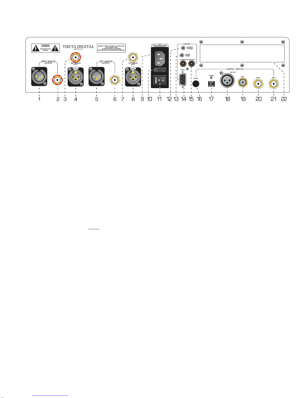
Rear Panel Layout
Figure 3 - Rear Panel Layout
1. Right Balanced Output.
2. Right Single-Ended Output (RCA).
3. Right Analog Input (RCA)
4. Right Balanced Analog Input.
5. Left Balanced Output.
6. Left Single-Ended Output (RCA).
7. Left Analog Input (RCA)
8. Left Balanced Analog Input.
9. AC Power input connector: 3 wire, IEC 320 standard with an EMI filter.
10. Fuse Holder. Fuse @ 100 & 110V = 630mA/250V, Fuse @ 220V = 3/8A/250V.
11. Main Power Switch. Master power switch. Disconnects AC to all circuits. It is recommended that this be left
ON at all times during regular use with the exception of whenever cables are connected/disconnected or when
the unit is not going to be used for an extended period of time. When this switch is turned on, the display will
momentarily show the unit’s serial number.
12. IR Remote Extender jack. An externally mounted (remote) Infrared Receiver (IR) plugs into this miniature stereo
phono jack. The signal must be demodulated. Please refer to Appendix D on page 23 for additional information.
13. Remote Trigger jack. Activated/deactivated (toggle) when the STANDBY button is pressed. The trigger can be
set to be either an input or output and function with either 12VDC or a 12V pulse (variable duration). The default
is a DC Output.
14. RS232 connector (DB9).
15. External Volume Data inputs. When the Generation VIII is used as an external DAC with the Theta Casablanca
or Casa Nova, output volume can be controlled from the processor. This is a proprietary digital data input.
16. Optional optical input (AT&T)
17. TosLink optical input
18. AES/EBU Digital input.
19. BNC digital input
20. Coaxial digital input # 2 (RCA)
21. Coaxial digital input # 1 (RCA)
22. Auxiliary Digital Input board.

7
Menu Maps
Setup Menu Pages
Within the Setup feature, following are all possible Setup menu pages:
** Not accessible when fixed volume option is installed.
Figure 4 - Setup Menu Pages

8
Remote Control
1. Standby button. After the rear panel MAIN POWER
switch is turned on, press the front panel STANDBY
button to exit the standby mode. The Gen VIII will
quickly initialize. The VFD will default to the last
selected INPUT. Pressing STANDBY again will
place the Generation VIII into standby mode and the
LED in the front panel STANDBY button will light.
Each time the unit is put into standby, the VFD will
“exercise” itself for 10 seconds by illuminating all
pixels. (This will enhance the lifetime of the VFD).
The Standby button is inactive when the Generation
VIII is in SETUP.
2. Input Select buttons 1through 5. Used to select a
desired INPUT, or to change a parameter when in a
submenu. The LED in the button lights when the
button is pressed.
3. The DISPLAY button will cycle the VFD brightness
through full brightness, ¾, ½, ¼ and off.
4. Mute button. Mutes/unmutes all audio outputs. Not
active when optional fixed volume cards are installed.
5. Setup button. Used to enter/exit the SETUP menus,
when setting all user parameters.
6. Level Up/Down buttons. Increases/decreases
master volume. Also used to increment/decrement
values in the SETUP menus.
7. Level Left/Right buttons. Shifts audio balance to
the left and right, or adjusts the master volume within
submenus when the LEVEL UP/DOWN buttons are
used for parameter value editing.
8. Phase button. Toggles the phase (0-180°) of all
speaker outputs.
Figure 5 - Remote Control
Note: When operating the hand held remote control, point it at the remote sensor on the Generation VIII’s front panel. The
remote control can be used 3 to 20 feet from the Generation VIII and within a 30oangle from each side of the sensor.
Exposing the remote sensor to direct sunlight or strong light may cause faulty operation.

9
Introduction to the User interface
The menu system within the Generation VIII is no deeper than 2 layers. When the SETUP button is pressed the
first setup page is shown. There is a “>” symbol above the # 5button at all times when in Setup. This indicates
that there is another page of setup parameters. While in setup, simply pressing button # 5repeatedly will take
the user through all of the SETUP pages. This is a loop and will ultimately bring the user back to the first
SETUP page. Please refer to Figure 4 for an overall view of all SETUP menus.
The first four SETUP menu pages contain parameters that can be stored uniquely for each of the five INPUT
SELECT buttons. The remaining SETUP pages are parameters which are global to the Generation VIII.
Once a parameter is selected for editing, pressing the LEVEL UP/DOWN buttons edits the parameter value,
storing it at the same time. On any SETUP page, the LEVEL LEFT/RIGHT buttons will adjust the master
volume.
To exit the SETUP menu, simply press the SETUP button again.
* * *
In the past, Theta has offered various options with their products. With the Generation VIII, most of these
options are pre-installed into the ‘base’ model. One important option remains - the ability to have the
Generation VIII be both a processor and a preamp. In older Generation VIIIs, this was achieved by having
either fixed volume controls or variable volume controls installed at the time of purchase. With software version
0.26 and higher, all new units will have variable volume controls installed as the user can program any input(s)
to be fixed or variable.
Generation VIII’s with fixed volume controls can use software version 0.26 or higher but will not have the benefit
of the volume related features. If desired, these Generation VIII’s can have their volume cards updated.
This manual describes the operations and menus as if the variable volume controls are installed. In each
section, menus, structures and instructional changes are indicated where they apply to a Generation VIII with
fixed volume controls.
10
OPERATIONS
This section describes the functionality of each button on the Generation VIII’s front panel.
Input Select Buttons
When the Generation VIII is first powered up via the MAIN POWER switch on the back panel, it will check all
installed software and hardware, momentarily display the unit serial number, and then revert to the standby mode.
The STANDBY LED will be lit.
After pressing the STANDBY button on the front panel, the display will show the start-up routine and then the
INPUT SELECT page, shown below in Figure 6. As this menu appears, the STANDBY LED turns off. This
display will be on during normal operation and will change only when the SETUP or balance (LEVELS
LEFT/RIGHT) buttons are pressed.
Changing Inputs
The INPUT NAMES shown in this figure are the default names only, and may differ from the user’s setup. There
are a total of 5 inputs. Buttons 1through 5are used to select a desired input, or audio source. The LED in the
selected button will illuminate when pressed. When the Generation VIII exits the standby mode, the last active
INPUT SELECT will be selected.
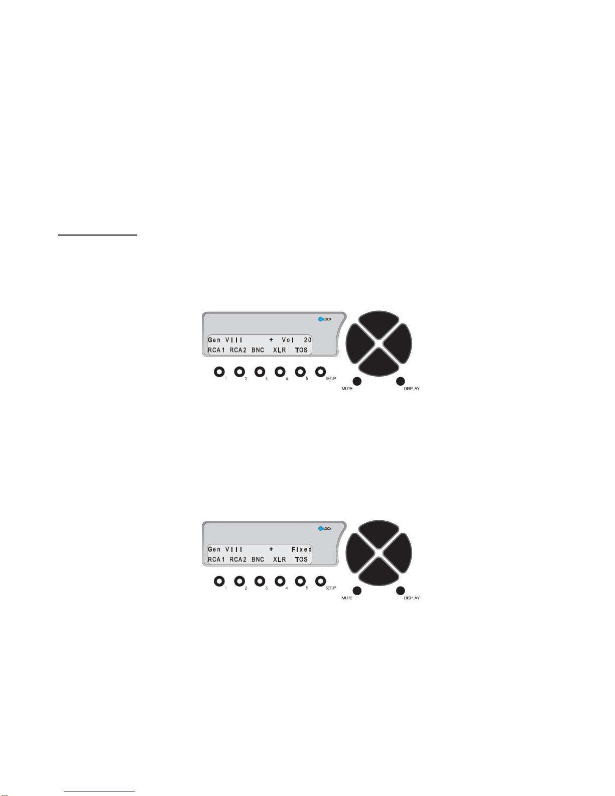
Figure 6 - Front Panel Display of the INPUT SELECT page
Pressing the LEVEL UP/DOWN buttons will adjust the master volume for all speakers. This value ranges from 0
to 86, relative maximum.
It is important to note that if the Fixed Volume Control option is installed, the “Vol” parameter in the display will
indicate the word “Fixed”. If the LEVEL UP/DOWN; MUTE; and/or BALANCE buttons are pressed, the word
Fixed will flash and the above mentioned buttons will have no effect. An example of this menu is shown in Figure
7 below.
Figure 7 - Front Panel Display of the INPUT SELECT page
when Fixed Volume Controls are installed
* * *
The DISPLAY button will cycle the VFD brightness through full brightness, ¾, ½, ¼ and off.
The MUTE button mutes/unmutes all audio outputs. It is not active when optional fixed volume cards are
installed.

11
SETUP
This function provides access to a series of submenus that will allow the configuration of the Generation VIII. In
this section, each feature of the SETUP menu is discussed in detail along with a diagram of each VFD display.
Pressing the SETUP button once changes the front panel display to the first page of the SETUP menu, shown in
Figure 8. Pressing button # 5(>) allows the user to enter into a series of Setup menu pages that permit the
configuration of all parameters that are programmable, both by INPUT SELECT button and global.
The master volume level is shown in the upper right corner of each SETUP menu.
Figure 8 - Front Panel Display of the Jack Map and Input Name SETUP menu
Jack and Input Names
Each physical input jack can be assigned, or “mapped” to any INPUT SELECT button. INPUT SELECT button
names can be changed.
Pressing button # 1allows the user to select which INPUT is to be edited. Use the LEVEL UP/DOWN buttons to
change the parameter.
Use button # 2to reassign a rear panel input jack to the currently selected front panel INPUT SELECT button.
Jack Definition
RCA 1 Rear panel RCA 1 input jack
RCA 2 Rear panel RCA 2 input jack
BNC Rear panel BNC input jack
XLR Rear panel AES/EBU input jack
TOS Rear panel TosLink input jack
Optical Rear panel Optical input jack
Ana Bal Rear panel Balanced Analog input jack
Ana S.E. Rear panel Single-Ended Analog input jack
Table 2 – Display Jack Name Abbreviations & Definitions
Button # 4 allows the user to select a name for the currently selected INPUT, or INPUT SELECT button. In
Figure 8, the rear panel RCA 1 jack is mapped to INPUT SELECT button # 1and INPUT SELECT # 1is named
CD.
The possible INPUT SELECT names are as follows:
RCA1, RCA 2, BNC, XLR, TOS, Opti, Abal, A se, CD, CD 1, CD 2, DVD, DVD1, DVD2, Phon, Tune, AM, FM, TV,
and “number’. If ‘number’ is selected, the name will be the number of the currently selected INPUT SELECT.
From this SETUP menu, pressing button # 5takes the user to the second page, shown in Figure 9.

12
Clocking
A re-clocking circuit typically converts poor quality jitter-ridden signals into high-quality transformer-isolated ones.
The Generation VIII uses this standard design to re-clock. The Generation VIII also has an advanced proprietary
synthesized anti-jitter circuit known as “Jitter Jail”. Either clocking type can be selected by the user, via button #
2.
Figure 9 - Front Panel Display of the Input Clocking SETUP menu
In this menu the user can first select the INPUT to which the clocking type is applied (button # 1), then select the
choice of clocking. Theta's proprietary Jitter Jail technology virtually eliminates jitter. The circuitry stores all
digital audio in a buffer where the signal aligns perfectly and then re-clocks it to the DACs using a high-precision
crystal oscillator and DSP algorithm. The resulting rock-stable digital audio suffers none of the problems
associated with ordinary, jitter-prone processors. Reclocking simply re-clocks the incoming signal.
Note: When using multiple Generation VIII’s with a single source it is best to select Reclocking so that each
Generation VIII’s data clock will be synchronized with the incoming data clock.
Press the SETUP button once to exit the menu.
Unity Gain
Each INPUT SELECT button on the Generation VIII can be programmed to either pass the incoming input signal
to the output jacks at unity gain, or attenuate it.
Figure 10 - Front Panel Display of the Unity Gain SETUP menu
Use button # 1to select which INPUT SELECT button to change the Unity Gain value of. When Unity Gain is set
to ON (via button # 2), the output level of incoming signal will not be affected by the Generation VIII’s volume
control. In this condition, the volume level will not appear in this menu. When Unity Gain is set to ON, signals
applied to the currently selected Input cannot be controlled by the Gen VIII’s volume controls.
Warning: When Unity Gain is set to ON, all incoming signals will output from the Generation VIII at FULL volume!
Note: Mute and Master Volume are disabled when Unity Gain is set to ON.
Press the SETUP button once to exit the menu.
Input Offset Level

13
In order to match the levels of signals on different INPUTS of the Generation VIII, there is a menu whereby the
user can offset the level of a given INPUT, from that of the Master Volume. This applies only when Unity Gain is
set to OFF. The range is 0to –86, where 0is the default setting. If the offset value were to be set to –5, then the
output level of the currently selected INPUT would be 5 less than the value of the Master Volume.
Figure 11 - Front Panel Display of the Offset Level SETUP menu
Note: If Unity Gain is set to ON, then the Offset Level value will be displayed as N/A since there can be no
volume control in a unity gain structure.
Press the SETUP button once to exit the menu.
Burn In
All new in-circuit devices and cables require a burn in period. The Generation VIII provides a white noise that can
be used to evenly expedite this process. Connect all component devices and cables in the system and go to the
“Burn in signal” menu. (SETUP, # 5twice). This feature is helpful in warming up the Generation VIII circuitry if it
has been off for some time.
Figure 12 - Front Panel Display of the Burn In Signal SETUP menu
Press button # 1and use the LEVEL UP/DOWN buttons to turn the noise signal ON or OFF. The typical burn in
time (when components are not turned completely off) is 60 to 100 hours.
Press the SETUP button once to exit the menu.
Remote Triggering
Figure 13 - Front Panel Display of the Remote Trigger SETUP menu
Table of contents


