Thiele Mission 6K Series User manual
Electrical System for Continuity
,GQQGML
*
**
*
*
**
*
^ŝŶŐůĞWŚĂƐĞhW^
YOUR CONNECTION TO SAFETY
Thiele KG • Vorderer Weinberg 26 • D-71522 Backnang • Tel.: +49 (0)7191 3560-0 • Fax.: +49 (0)7191 3560-19 • [email protected] • www.thiele-kg.de
Thiele KG • Vorderer Weinberg 26 • D-71522 Backnang • Tel.: +49 (0)7191 3560-0 • Fax.: +49 (0)7191 3560-19 • [email protected] • www.thiele-kg.de
YOUR CONNECTION TO SAFETY
klick to
www
u-s-v
YOUR CONNECTION TO SAFETY
klick to
www
ACDC-DCDC
YOUR CONNECTION TO SAFETY
klick to
www
SYSTEME
YOUR CONNECTION TO SAFETY
klick to
www
CONTACT
YOUR CONNECTION TO SAFETY
klick to
www
CALLBACK

D/^^/KEϲ<භϭϬ<
^/E'>W,^
Rev. 02 –13 October 2015
2
Contents
1. Safety......................................................................................................................................................3
1.1 Safety..............................................................................................................................................3
1.2 Symbol Description ........................................................................................................................3
2. Product Introduction.............................................................................................................................5
2.1 The appearance of the product......................................................................................................5
2.2 The principle of the product............................................................................................................6
2.3 Product Category ...........................................................................................................................6
3. Installation..............................................................................................................................................7
3.1 Unpacking and inspection..............................................................................................................7
3.2 Installation note ..............................................................................................................................7
3.3 UPS input and output connection...................................................................................................8
3.4 Connection of the UPS communication Cables.............................................................................8
3.5 Parallel card (Optional)...................................................................................................................9
3.6 External battery conection (for extend model only) .....................................................................10
4. Panel display, operation and running ...............................................................................................12
4.1 Start up and turn off UPS .............................................................................................................12
4.1.1 Start up operation..............................................................................................................12
4.1.2 Turn off operation..............................................................................................................12
4.2 Faceplate display .........................................................................................................................12
4.2.1 Faceplate display illumination...........................................................................................12
4.2.2 LCD display.......................................................................................................................13
4.3 Parameters setting.......................................................................................................................16
4.3.1 Mode setting......................................................................................................................16
4.3.2 Output voltage class setting..............................................................................................16
4.3.3 Input/Output frequency class setting ................................................................................17
4.3.4 Battery capacity setting.....................................................................................................17
4.3.5 Battery quantity setting .....................................................................................................18
4.3.6 Bypass Volt-HI setting.......................................................................................................18
4.3.7 Bypass Volt-Low setting....................................................................................................19
4.3.8 Buzzer Mute Setting..........................................................................................................19
4.3.9 Battery Test Setting...........................................................................................................20
4.3.10 Parallel ID setting..............................................................................................................21
4.3.11 Parallel quantity setting.....................................................................................................21
4.3.12 Parallel redundancy quantity setting.................................................................................22
4.4 Display Messages/record.............................................................................................................23
4.4.1 Operational Status and Mode ...........................................................................................23
4.4.2 Modes and Alarm Information...........................................................................................23
5. Maintenance.........................................................................................................................................24
5.1 Battery maintenance........................................................................................................................24
6. Troubleshooting and performance of the product ..........................................................................25
6.1 Troubleshooting............................................................................................................................25
6.2 EMC standard/Safety standard....................................................................................................25
6.3 Product Performance ...................................................................................................................26
7. RS232 Communication port definition..............................................................................................28
Thank you for purchasing this series UPS.
This series UPS is an intelligent, Single phase in Single phase out, high frequency online UPS designed by our R&D team who is with years of
designing experiences on UPS. With excellent electrical performance, perfect intelligent monitoring and network functions, smart appearance,
complying with EMC and safety standards, The UPS meets the world’s advanced level.
Read this manual carefully before installation
This manual provides technical support to the operator of the equipment.
Note: Because of the continuous improvements, our products may differ somewhat from the contents included in this manual. You can contact
local office to get the information when necessary.
YOUR CONNECTION TO SAFETY
Thiele KG • Vorderer Weinberg 26 • D-71522 Backnang • Tel.: +49 (0)7191 3560-0 • Fax.: +49 (0)7191 3560-19 • [email protected] • www.thiele-kg.de
Thiele KG • Vorderer Weinberg 26 • D-71522 Backnang • Tel.: +49 (0)7191 3560-0 • Fax.: +49 (0)7191 3560-19 • [email protected] • www.thiele-kg.de
YOUR CONNECTION TO SAFETY
klick to
www
u-s-v
YOUR CONNECTION TO SAFETY
klick to
www
ACDC-DCDC
YOUR CONNECTION TO SAFETY
klick to
www
SYSTEME
YOUR CONNECTION TO SAFETY
klick to
www
CONTACT
YOUR CONNECTION TO SAFETY
klick to
www
CALLBACK

D/^^/KEϲ<භϭϬ<
^/E'>W,^
Rev. 02 –13 October 2015
3
1. SAFETY
This chapter mainly introduces the safety signs and security considerations of MISSION 6K/10K series high
frequency online ups. Before any operation of equipment, you should read the content of this chapter carefully.
1.1 Safety
There exists dangerous voltage and high temperature inside the UPS. During the installation, operation and
maintenance, please abide the local safety instructions and relative laws, otherwise it will result in personnel
injury or equipment damage. Safety instructions in this manual act as a supplementary for the local safety
instructions. Our company will not assume the liability that caused by disobeying safety instructions.
Our company will not assume the liability that caused by disobey of safety instructions. Please note the
following:
1. Don’t use the UPS when the actual load exceeds the rated load.
2. There are high-capacity batteries in the standard type UPS. You must not open the enclosure or it will lead
to electric shock. If it needs internal maintenance or battery replacement, please send it to the designated
site.
3. Internal short-circuit of the UPS will cause electric shock or fire. So don’t place the containers equipped with
liquid on the top of the UPS so as not to cause danger of electric shock and so on.
4. Don’t put the UPS in a place with high temperature or humidity as well as the corrosive gas, much dust.
5. Keep good air circulation between in-vent on front panel and out-vent on back panel.
6. Avoid direct sunlight or near heat-dispensed objects.
7. In case that the smoke appears on the UPS, please cut off the power as soon as possible and contact the
dealer service site.
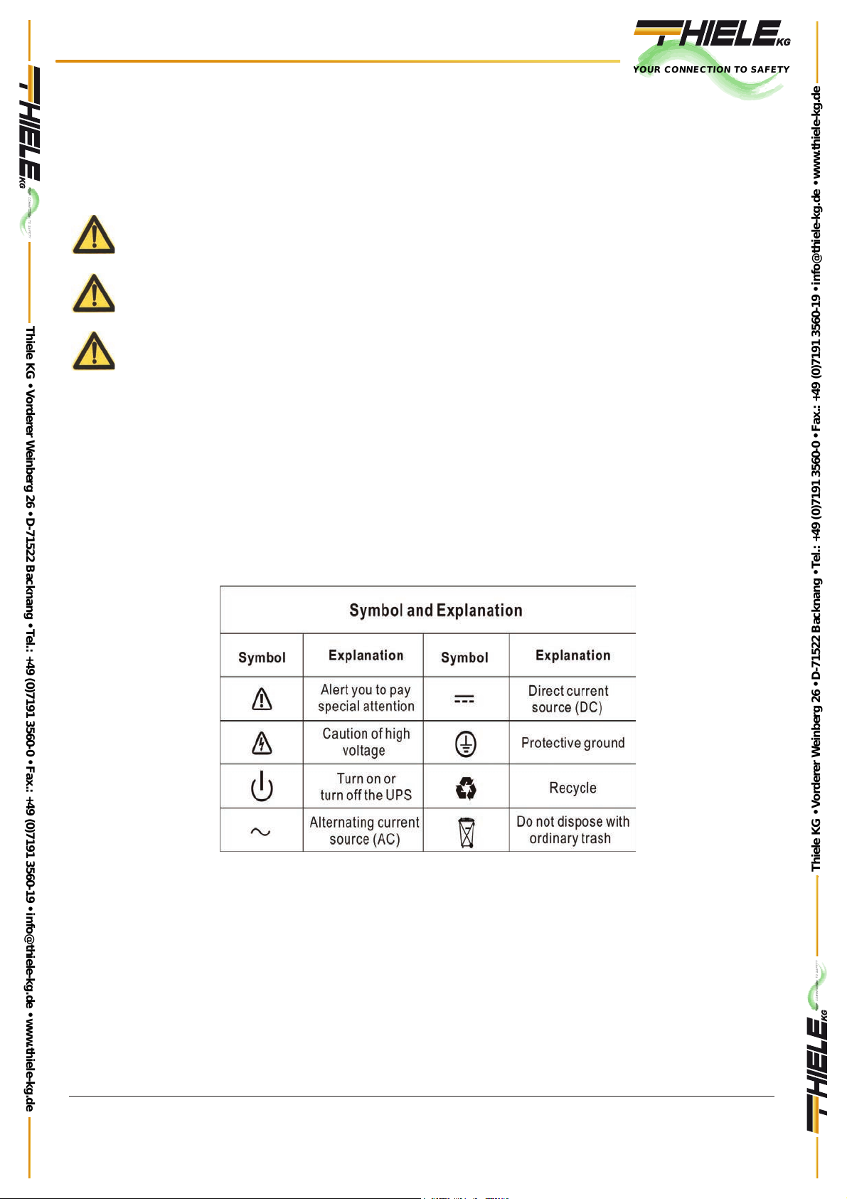
1.2 Symbol Description
The safety symbols cited in this manual are shown in Fig. 1-1, which are used to inform readers of safety issues
that should be obeyed when installation, operation and maintenance.
Fig.1-1 Symbol meanings
Safety Symbol Indication
Attention
Static discharge sensitive
Electric shock
YOUR CONNECTION TO SAFETY
Thiele KG • Vorderer Weinberg 26 • D-71522 Backnang • Tel.: +49 (0)7191 3560-0 • Fax.: +49 (0)7191 3560-19 • [email protected] • www.thiele-kg.de
Thiele KG • Vorderer Weinberg 26 • D-71522 Backnang • Tel.: +49 (0)7191 3560-0 • Fax.: +49 (0)7191 3560-19 • [email protected] • www.thiele-kg.de
YOUR CONNECTION TO SAFETY
klick to
www
u-s-v
YOUR CONNECTION TO SAFETY
klick to
www
ACDC-DCDC
YOUR CONNECTION TO SAFETY
klick to
www
SYSTEME
YOUR CONNECTION TO SAFETY
klick to
www
CONTACT
YOUR CONNECTION TO SAFETY
klick to
www
CALLBACK
D/^^/KEϲ<භϭϬ<
^/E'>W,^
Rev. 02 –13 October 2015
4
There are three levers of safety grade: Dangerous, Warning and Attention. The remark is on the right side of the
safety symbol, the detailed comments are shown as following:
Dangerous: Indicate risk of serious injury or death or seriously damage of the equipment.
Warning: Indicate risk of serious injury or damage of the equipment.
Attention: Indicate risk of injury or damage of the equipment.
Description of Commonly Used Symbols
Some or all of the following symbols may be used in this manual. It is advisable to familiarize yourself with them
and understand their meaning:
YOUR CONNECTION TO SAFETY
Thiele KG • Vorderer Weinberg 26 • D-71522 Backnang • Tel.: +49 (0)7191 3560-0 • Fax.: +49 (0)7191 3560-19 • [email protected] • www.thiele-kg.de
Thiele KG • Vorderer Weinberg 26 • D-71522 Backnang • Tel.: +49 (0)7191 3560-0 • Fax.: +49 (0)7191 3560-19 • [email protected] • www.thiele-kg.de
YOUR CONNECTION TO SAFETY
klick to
www
u-s-v
YOUR CONNECTION TO SAFETY
klick to
www
ACDC-DCDC
YOUR CONNECTION TO SAFETY
klick to
www
SYSTEME
YOUR CONNECTION TO SAFETY
klick to
www
CONTACT
YOUR CONNECTION TO SAFETY
klick to
www
CALLBACK
D/^^/KEϲ<භϭϬ<
^/E'>W,^
Rev. 02 –13 October 2015
5
2. PRODUCT INTRODUCTION
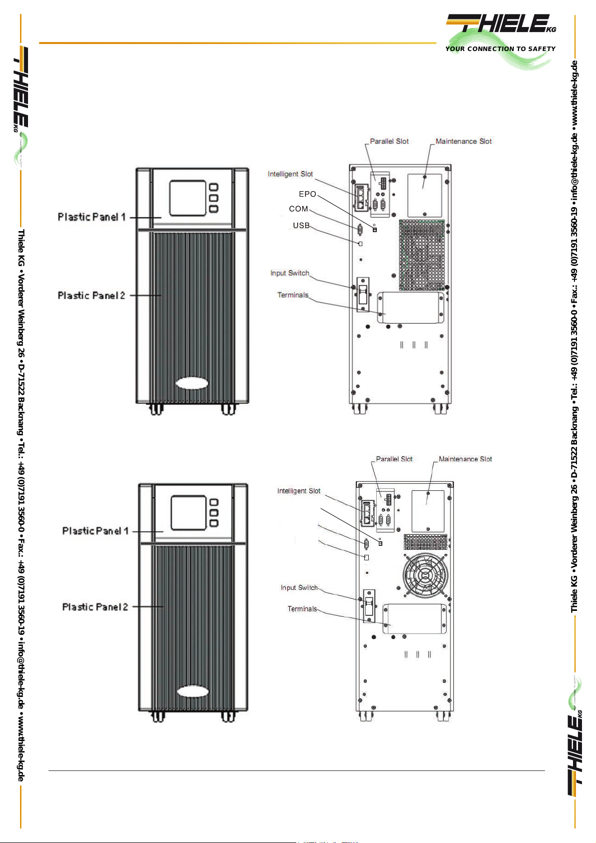
2.1 The appearance of the product
6KVA Front Panel view 6KVA Rear Panel view
USB
EPO
COM
10KVA Front Panel view 10KVA Rear Panel view
YOUR CONNECTION TO SAFETY
Thiele KG • Vorderer Weinberg 26 • D-71522 Backnang • Tel.: +49 (0)7191 3560-0 • Fax.: +49 (0)7191 3560-19 • [email protected] • www.thiele-kg.de
Thiele KG • Vorderer Weinberg 26 • D-71522 Backnang • Tel.: +49 (0)7191 3560-0 • Fax.: +49 (0)7191 3560-19 • [email protected] • www.thiele-kg.de
YOUR CONNECTION TO SAFETY
klick to
www
u-s-v
YOUR CONNECTION TO SAFETY
klick to
www
ACDC-DCDC
YOUR CONNECTION TO SAFETY
klick to
www
SYSTEME
YOUR CONNECTION TO SAFETY
klick to
www
CONTACT
YOUR CONNECTION TO SAFETY
klick to
www
CALLBACK
This manual suits for next models
1
Table of contents
Other Thiele UPS manuals


 Plus Startup manual")


