Thiele Tri-One 10000 User manual

Tri-One 10K-15K-20K
Three-phase in/Single-phase out UPS
Uninterruptible Power Supplies
YOUR CONNECTION TO SAFETY
Thiele KG • Vorderer Weinberg 26 • D-71522 Backnang • Tel.: +49 (0)7191 3560-0 • Fax.: +49 (0)7191 3560-19 • [email protected] • www.thiele-kg.de
Thiele KG • Vorderer Weinberg 26 • D-71522 Backnang • Tel.: +49 (0)7191 3560-0 • Fax.: +49 (0)7191 3560-19 • [email protected] • www.thiele-kg.de
YOUR CONNECTION TO SAFETY
klick to
www
u-s-v
YOUR CONNECTION TO SAFETY
klick to
www
ACDC-DCDC
YOUR CONNECTION TO SAFETY
klick to
www
SYSTEME
YOUR CONNECTION TO SAFETY
klick to
www
CONTACT
YOUR CONNECTION TO SAFETY
klick to
www
CALLBACK

Ver0217.11.2014 2
Contents
1. Safety 3
1.1 Safety instructions 3
1.2 Symbol description 4
2. Product introduction 5
2.1 UPS view 5
2.2 UPS operating principles 6
2.3 Applications 7
2.4 Characteristics 7
2.5 UPS models 7
3. Installation 8
3.1 Unpack checking 8
3.2 Installation procedure 8
3.3 UPS input and output connections 9
3.4 Connection of UPS communication cables 9
3.5 External battery connection (for extended autonomy time only)) 10
4. Control panel, configuration and operation 11
4.1 Operating mode 11
4.2 Start up and Turn off the UPS 11
4.3 Control Panel 12
4.4 Parameters setting 15
4.5 Working mode and switching 19
4.6 LED and message on Display 20
5. Maintenance 22
5.1 Battery manintenance 22
5.2 Fan maintenance 22
6. Trobleshooting and UPS features 22
6.1 Troubleshooting 22
6.2 UPS features 23
6.3 Environment 24
6.4 Mechanical 24
7. Communication Interface 25
8. Optional boards 25
9. Packaging contents 26
Warranty 27
Thank you for purchasing this UPS.
This series is an intelligent, three phase in single phase out, high frequency on-line UPS. With excellent
electrical performance, perfect intelligent monitoring and network functions, smart appearance, complying
with EMC and safety standards, the UPS meets the world’s advanced level.
Read this manual carefully before installation
This manual provides technical support to the operator of the equipment.
Information included in this document may chage without any notification.
YOUR CONNECTION TO SAFETY
Thiele KG • Vorderer Weinberg 26 • D-71522 Backnang • Tel.: +49 (0)7191 3560-0 • Fax.: +49 (0)7191 3560-19 • [email protected] • www.thiele-kg.de
Thiele KG • Vorderer Weinberg 26 • D-71522 Backnang • Tel.: +49 (0)7191 3560-0 • Fax.: +49 (0)7191 3560-19 • [email protected] • www.thiele-kg.de
YOUR CONNECTION TO SAFETY
klick to
www
u-s-v
YOUR CONNECTION TO SAFETY
klick to
www
ACDC-DCDC
YOUR CONNECTION TO SAFETY
klick to
www
SYSTEME
YOUR CONNECTION TO SAFETY
klick to
www
CONTACT
YOUR CONNECTION TO SAFETY
klick to
www
CALLBACK

Ver0217.11.2014 3
1. Safety
This section will introduce you to the symbols and to considerations about safety of Tri-One
series.
Pay attention to the contents of this section before each operation on the equipment. Contact
your reseller or distributor beforehand in case Ups should be used for particular applications that
have direct contact with people's lives, such as medical equipment, elevators, or similar, and he
will advise you in the proper way.
1.1 Safety Instructions
Within the UPS there are dangerous voltages and high temperatures. During installation,
maintenance, and normal operation, please comply with local safety instructions and local safety
laws, otherwise they may result in personal injury or damage to UPS. The safety instructions in
this manual are an addition to local safety regulations. Our Company does not assume any
responsibility for damage caused by non-compliance with the safety regulations..
xThere is a high risk of electric shock from the UPS inside, so please do not open or
remove the casing or front panel unless it is operated by authorized technicians;
otherwise, the warranty becomes void as well.
xThe output of standard UPS with internal batteries may be energized even if the UPS input
is not connected to the utility.
xDo disconnect the UPS input and make sure the UPS is completely off before moving
the UPS
xFor the sake of human being' safety, please well earth the UPS before starting it.
xWorking environment and storage way will affect the lifetime and reliability of the UPS.
Avoid having the UPS work under following environment for a long time:
oArea where the humidity and temperature is beyond the specified
range(temperature from 0Ԩto 40Ԩ, relative humidity 5%-95%).
oDirect sunlight and location nearby heat
oArea which can be crashed easily
oArea with corrosive gas, flammable gas, excessive dust...etc.
xKeep the ventilations in good conditions otherwise the temperature of components inside
UPS will be high and the component and UPS life will be affected..
xIt is forbidden to pour liquid or put any objects into the UPS.
xDon’t use liquid extinguisher if there is a fire, a dry powder extinguisher is recommended.
xBattery life cycle will be shorter as environment temperature rise. Replacing battery
periodically can help to keep the UPS in normal status and assure backup time required.
Battery replacement should be done by authorized technician.
xKeep the UPS in a dry area or environment if it will not be free of operation for a long time.
Storage temperature of UPS with internal battery is -20Ԩ~+55Ԩ,and extended backup
model without internal battery is -40Ԩ~+70Ԩ.
xDon’t open the battery, electrolyte inside will do harm to eyes and skin. Please use plenty
of clean water to wash if touching then go to see a doctor..
xDon’t dispose of the battery with fire so as to avoid explosion.
YOUR CONNECTION TO SAFETY
Thiele KG • Vorderer Weinberg 26 • D-71522 Backnang • Tel.: +49 (0)7191 3560-0 • Fax.: +49 (0)7191 3560-19 • [email protected] • www.thiele-kg.de
Thiele KG • Vorderer Weinberg 26 • D-71522 Backnang • Tel.: +49 (0)7191 3560-0 • Fax.: +49 (0)7191 3560-19 • [email protected] • www.thiele-kg.de
YOUR CONNECTION TO SAFETY
klick to
www
u-s-v
YOUR CONNECTION TO SAFETY
klick to
www
ACDC-DCDC
YOUR CONNECTION TO SAFETY
klick to
www
SYSTEME
YOUR CONNECTION TO SAFETY
klick to
www
CONTACT
YOUR CONNECTION TO SAFETY
klick to
www
CALLBACK

Ver0217.11.2014 4
1.2 Symbol Description
The safety symbols included in this manual are shown in the table below, which are used to
inform users of safety issues that should be obeyed when installation, operation and
maintenance.
SIMBOLO
INDICAZIONE
SIMBOLO
SPIEGAZIONE
SIMBOLO
SPIEGAZIONE
Attention
Warning
–
High
attention
Direct current
(DC)
Static discherge
sensitive Warning
High voltage
Ground connection
Electric shock
Switch On or Switch
Off the Ups
Recycle material
Alternate current (AC)
Don’t dispose
There are three levels of safety grade: Dangerous, Warning, Attention. Remarks on the right
side of the safety symbol, the detailed comments are shown as following:
Dangerous: Indicate risk of serious injury or death or seriously damage of the
equipment.
Warning: Indicate risk of serious injury or damage of the equipment.
Caution: Indicate risk of injury or damage of the equipmen.
YOUR CONNECTION TO SAFETY
Thiele KG • Vorderer Weinberg 26 • D-71522 Backnang • Tel.: +49 (0)7191 3560-0 • Fax.: +49 (0)7191 3560-19 • [email protected] • www.thiele-kg.de
Thiele KG • Vorderer Weinberg 26 • D-71522 Backnang • Tel.: +49 (0)7191 3560-0 • Fax.: +49 (0)7191 3560-19 • [email protected] • www.thiele-kg.de
YOUR CONNECTION TO SAFETY
klick to
www
u-s-v
YOUR CONNECTION TO SAFETY
klick to
www
ACDC-DCDC
YOUR CONNECTION TO SAFETY
klick to
www
SYSTEME
YOUR CONNECTION TO SAFETY
klick to
www
CONTACT
YOUR CONNECTION TO SAFETY
klick to
www
CALLBACK
Ver0217.11.2014 5
2. Product Introduction
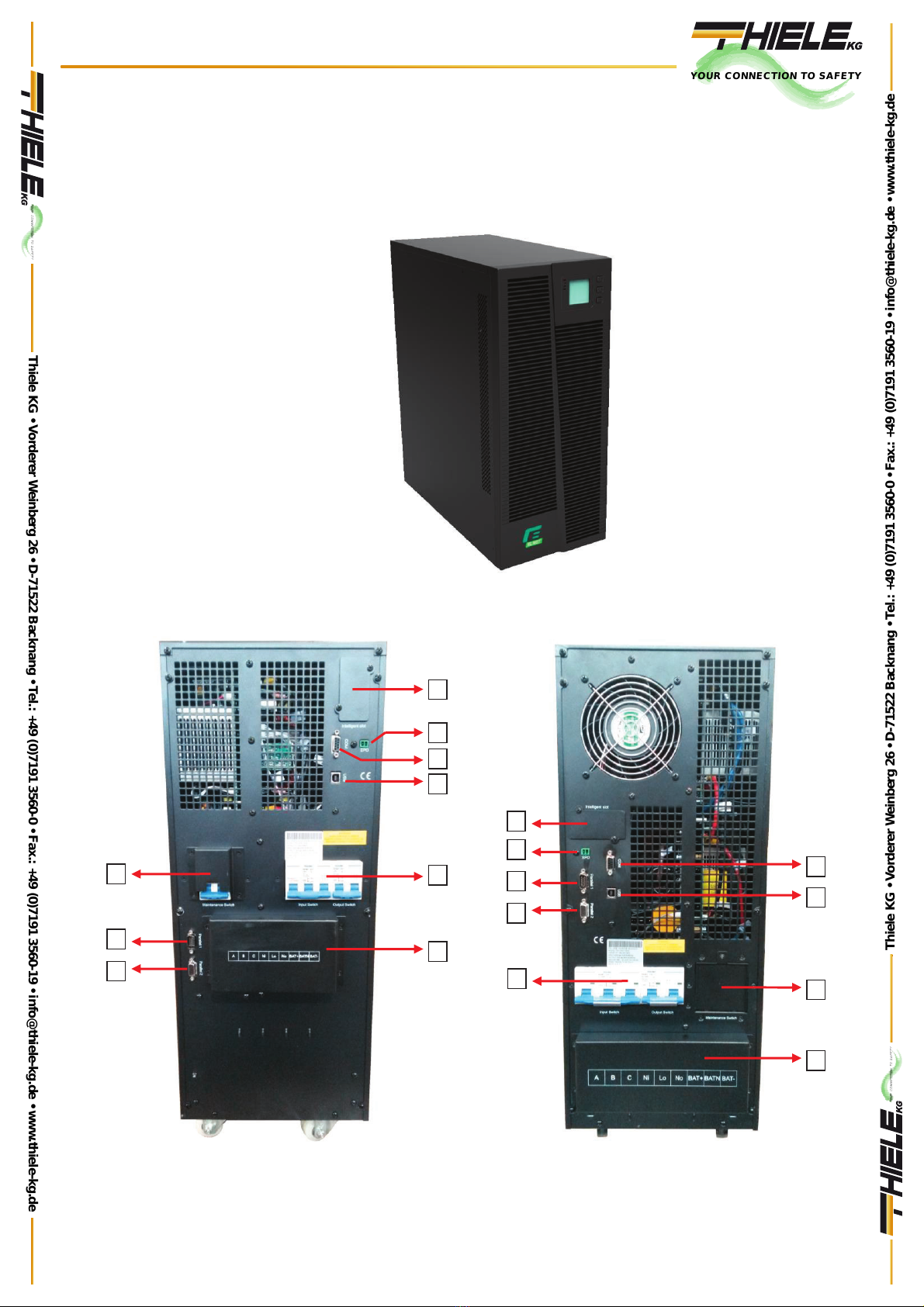
2.1 UPS view
UPS front view (all models)
10KVA –Rear view 15-20KVA –Rear view
5
4
6
7
4
8
9
1
2
3
4
5
2
3
8
9
1
7
6
YOUR CONNECTION TO SAFETY
Thiele KG • Vorderer Weinberg 26 • D-71522 Backnang • Tel.: +49 (0)7191 3560-0 • Fax.: +49 (0)7191 3560-19 • [email protected] • www.thiele-kg.de
Thiele KG • Vorderer Weinberg 26 • D-71522 Backnang • Tel.: +49 (0)7191 3560-0 • Fax.: +49 (0)7191 3560-19 • [email protected] • www.thiele-kg.de
YOUR CONNECTION TO SAFETY
klick to
www
u-s-v
YOUR CONNECTION TO SAFETY
klick to
www
ACDC-DCDC
YOUR CONNECTION TO SAFETY
klick to
www
SYSTEME
YOUR CONNECTION TO SAFETY
klick to
www
CONTACT
YOUR CONNECTION TO SAFETY
klick to
www
CALLBACK

Ver0217.11.2014 6
1) Manual By-Pass
2) Parallel Port #1 (disabled)
3) Parallel Port #2 (disabled)
4) Intelligent Slot for Relay / SNMP card (cards are optional)
5) EPO connector
6) COM port (RS232)
7) USB port
8) Input/Output switches
9) Terminal blocks (Input/Output/Batteries)
2.2 UPS operating principles
The system can work as a single unit or parallel one, so as to enhance its reliability
1. AC input filter for filtering input disturbances.
2. Rectifier. To convert AC input voltage into a DC voltage and to increase (boost) the DC
voltage at Inverter.
3. DC/DC Converter (booster): When UPs operates in battery mode, it increase the DC voltage
and supply the inverter.
4. Inverter: to convert the DC voltage into an AC filtered voltage at the output.
5. Bypass: When UPS face an overload or a failure on the inverter, the load is automatically
transferred to Bypass line without any interruption of power to the load.
6. Battery charger: The standard charger feeds the batteries with 1A current. For longer
autonomy times, an optional battery charger at 10A max. is available
7. Battery: VRLA Lead-acid, maintenance-free.
8. Output Filter: to filter the output voltage in order to feed the load with a clean voltage.
9. Maintenance bypass switch is provided so the supply to load will not be interrupted during
repair or maintenance.
Rectifier
Inverter
Switch
Charger
AC input
Input switch
Bypass
Maintenance switch
AC Output
Battery
YOUR CONNECTION TO SAFETY
Thiele KG • Vorderer Weinberg 26 • D-71522 Backnang • Tel.: +49 (0)7191 3560-0 • Fax.: +49 (0)7191 3560-19 • [email protected] • www.thiele-kg.de
Thiele KG • Vorderer Weinberg 26 • D-71522 Backnang • Tel.: +49 (0)7191 3560-0 • Fax.: +49 (0)7191 3560-19 • [email protected] • www.thiele-kg.de
YOUR CONNECTION TO SAFETY
klick to
www
u-s-v
YOUR CONNECTION TO SAFETY
klick to
www
ACDC-DCDC
YOUR CONNECTION TO SAFETY
klick to
www
SYSTEME
YOUR CONNECTION TO SAFETY
klick to
www
CONTACT
YOUR CONNECTION TO SAFETY
klick to
www
CALLBACK
Ver0217.11.2014 7
2.3 Applications
This series UPS, providing reliable AC power to various equipment, can be used for
computer center, network management center, auto control system, telecom systems, etc
2.4 Characteristics
xThis series is an intelligent online sine wave UPS.
oHigh frequency, double conversion, high input power factor, wide input
voltage range, the output will not be disturbed by power network, suitable for
area with poor power supply condition.
oDSP technology for all-digital control, high reliability, self-diagnostics and
protections are featured.
oIntelligent battery management which extends battery life.
oLCD panel and LED indicators clearly indicate the system status and
parameters such as input/output voltage, frequency, load, temperature
inside UPS, etc.
oPerfect network power management can be achieved by using UPS
monitoring software.
oMaintenance bypass switch is provided so the power supply to load will not
be interrupted during repair.
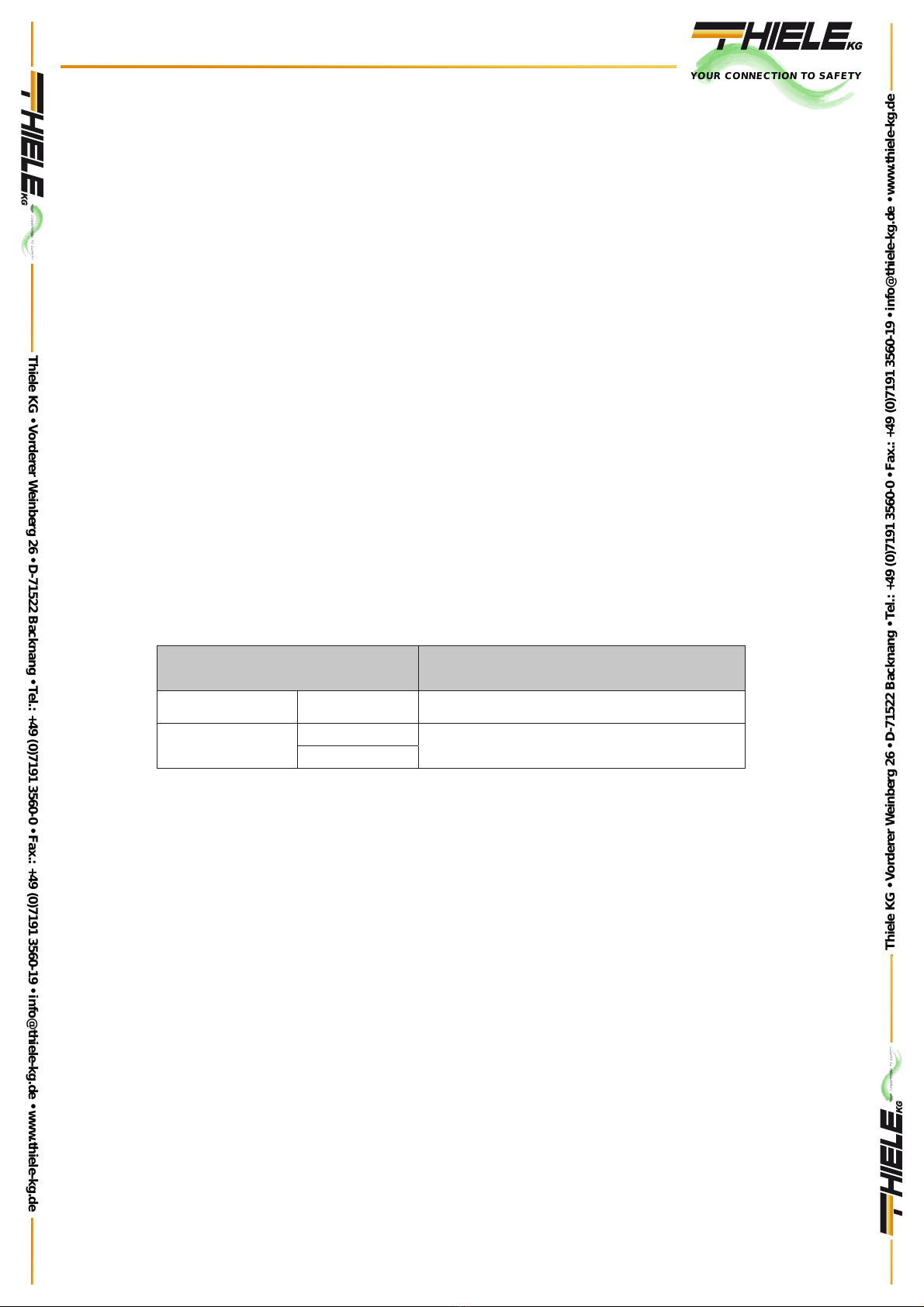
2.5 UPS Models
MODEL UPS DESCRIZIONE
Standard Unit
With internal battery
10KVA
(S)
16 (standard) 18-20 (optional)
Standard Unit
With
ex
ternal battery
15KVA (H)
16-18-20
20KVA (H)
YOUR CONNECTION TO SAFETY
Thiele KG • Vorderer Weinberg 26 • D-71522 Backnang • Tel.: +49 (0)7191 3560-0 • Fax.: +49 (0)7191 3560-19 • [email protected] • www.thiele-kg.de
Thiele KG • Vorderer Weinberg 26 • D-71522 Backnang • Tel.: +49 (0)7191 3560-0 • Fax.: +49 (0)7191 3560-19 • [email protected] • www.thiele-kg.de
YOUR CONNECTION TO SAFETY
klick to
www
u-s-v
YOUR CONNECTION TO SAFETY
klick to
www
ACDC-DCDC
YOUR CONNECTION TO SAFETY
klick to
www
SYSTEME
YOUR CONNECTION TO SAFETY
klick to
www
CONTACT
YOUR CONNECTION TO SAFETY
klick to
www
CALLBACK
Ver0217.11.2014 8
3. Installation
3.1 Unpack checking
1) Don’t lean the UPS when moving it out from the packaging.
2) Check the appearance to see if the UPS is damaged during transportation, do
not switch on the UPS if any damaged is found and please contact the dealer.
3) Check the accessories according to the packing list and contact the dealer if any
parts missing
4) Verify that UPS is suitable for your application, by checking the characteristics of
the model written on the label placed on rear panel of the device.
3.2 Installation Procedure
* Put the UPS at flat place next to the equipment.
* Keep the UPS at least 20cm from wall or equipment or other object. Don’t block the ventilation
holes of the UPS located in the front panel and the bottom part, so as to keep the ventilation in
good condition & avoid temperature of components inside getting high.
* Keep the UPS away from high temperature, water, flammable gas, corrosive gas, dust, direct
sunlight and explosive things
* Don't lay the UPS outdoor.
* PDU is required to connect to the UPS output so as to weaken the affection between loads
* In order to fix the UPS, please lock its wheels by shifting the sheet on each wheel.
* RCD load like computer ,linear load and small inductive load can be connected with the UPS.
Please contact dealer if other types of loads is required to be connected with.
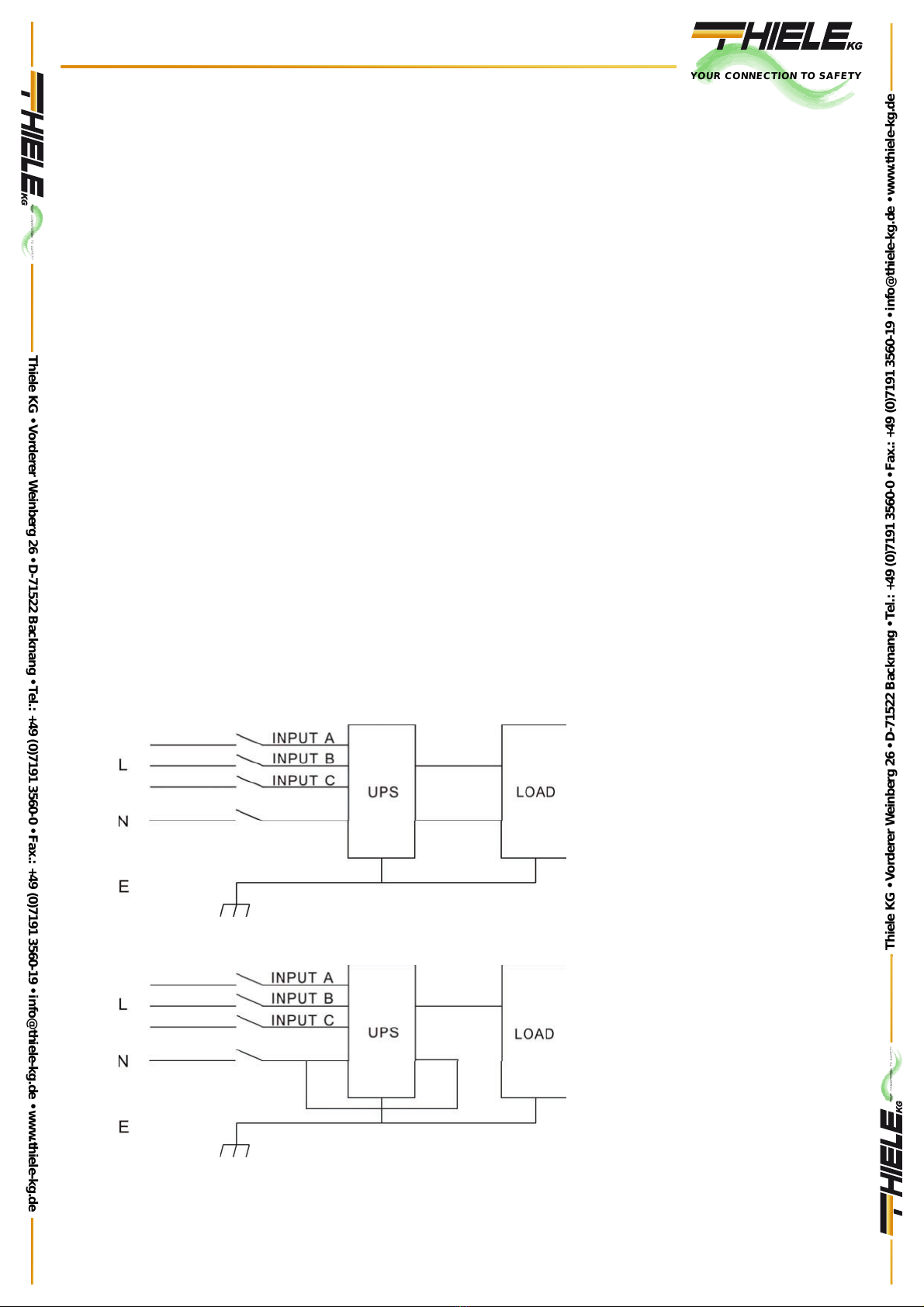
* For the safety sake of user and equipment, please betake correct power configuration (Fig. 1,
2).
Fig.1 Correct connections
Fig.2 Wrong connection
YOUR CONNECTION TO SAFETY
Thiele KG • Vorderer Weinberg 26 • D-71522 Backnang • Tel.: +49 (0)7191 3560-0 • Fax.: +49 (0)7191 3560-19 • [email protected] • www.thiele-kg.de
Thiele KG • Vorderer Weinberg 26 • D-71522 Backnang • Tel.: +49 (0)7191 3560-0 • Fax.: +49 (0)7191 3560-19 • [email protected] • www.thiele-kg.de
YOUR CONNECTION TO SAFETY
klick to
www
u-s-v
YOUR CONNECTION TO SAFETY
klick to
www
ACDC-DCDC
YOUR CONNECTION TO SAFETY
klick to
www
SYSTEME
YOUR CONNECTION TO SAFETY
klick to
www
CONTACT
YOUR CONNECTION TO SAFETY
klick to
www
CALLBACK

Ver0217.11.2014 9
3.3 UPS input and output connections
Sizing of the cables at input, output and battery, please refer to the below table:
1) Switch Off all breakers before connecting cables..
2) Remove the cover of terminal blocks and connect the cables correspondingly.
3) Connect the UPS output L, N, E to L, N, E of load via a PDU. Tighten the screws and
shelter the terminals.
UPS
CABLES DIMENSION (mm2)
INPUT
OUTPUT
BATTERIES
GND
10KVA
4 x 10
2 x 10
3x16
10
15KVA
4 x 10
2 x 16
3x25
16
20KVA
4 x 16
2 x 25
3x25
25
A/B/C/Ni INPUT section
Lo-No OUTPUT
section
BAT+/BATN/BAT- BATTERY
section
GND GROUND
CONNECTION
Fig.3 Connections on terminal block
3.4 Connection of UPS communication cables
1) For local monitoring of UPS, a USB cable provided in accessories can be used to connect
the UPS with PC in order to install UPSilon2000 software.
2) For remote monitoring of UPS an SNMP card (optional) must be installed.
A. Remove the cover of SNMP slot at UPS rear panel and keep it for further use.
B. Insert the SNMP card and tighten the screws
C. Connect the UPS with internet by network cable.
D. Refer to the SNMP manual provided to do SNMP setting.
CAUTION!
Cables need terminal to ensure correct connection.
Don’t reverse input phase (L) and
Neutral (N).
Don’t connect the UPS to a wall outlet because may get burnt. Connect to an electrical panel.
YOUR CONNECTION TO SAFETY
Thiele KG • Vorderer Weinberg 26 • D-71522 Backnang • Tel.: +49 (0)7191 3560-0 • Fax.: +49 (0)7191 3560-19 • [email protected] • www.thiele-kg.de
Thiele KG • Vorderer Weinberg 26 • D-71522 Backnang • Tel.: +49 (0)7191 3560-0 • Fax.: +49 (0)7191 3560-19 • [email protected] • www.thiele-kg.de
YOUR CONNECTION TO SAFETY
klick to
www
u-s-v
YOUR CONNECTION TO SAFETY
klick to
www
ACDC-DCDC
YOUR CONNECTION TO SAFETY
klick to
www
SYSTEME
YOUR CONNECTION TO SAFETY
klick to
www
CONTACT
YOUR CONNECTION TO SAFETY
klick to
www
CALLBACK

Ver0217.11.2014 10
3.5 External battery connection (for extended autonomy time
only)
Make sure that battery quantity complies with the spec. (16/18/20 blocks at 12V in series). Make
sure that the voltage of battery bank is 192/216/240Vdc.
CAUTION:
1) Don’t mix batteries with different capacity & brands and don’t mix brand new and old
batteries.
2) Standard configuration is made by 16 blocks with a max. capacity of 65Ah (battery charger
at 6A). When using a configuration with 18 or 20 blocks, then switch On the UPS with
mains is present and configure the exact number of blocks in order to split correctly the
charging current.
3) The breaker on battery cabinet should be off.
4) Take out the connection box and remove the cover of terminals, make sure there is no DC
voltage at the battery terminals of UPS.
5) Connect battery pole with positive pole, common pole and negative pole to battery
connector (BAT+,BATN,BAT-㸧,don’t reverse battery connection (Fig. 5).
Fig.5 External battery cabinet
connection
CAUTION:
xMake sure the UPS is Off and battery breaker is Off before installing the batteries..Don’t
wear any watch, rings or similar, to avoid any accidental shortcircuit.
xDon’t reverse nor shortcircuit the cables. Red cable must be connected to “+” positive pole
and black cable must be connected to “-”.negative pole
xUse tools with isolated handle. don’t put any object on top of batteries.
CAUTION:
xConnection cables section must be compliant to the Standard when using an external
battery cabinet.
xWhen connecting the load to the UPS, make sure that UPS and load are Off. In case of
multiple loads, then connect them once a time.
xDon’t connect to Ups load such as copier machine, inductive load (engine), fluorescent
lamps, to avoid any damage to UPS.
xIt is recommended to connect the UPS to the mains by means of an input breaker. Make
sure that ground connection is implemented.
YOUR CONNECTION TO SAFETY
Thiele KG • Vorderer Weinberg 26 • D-71522 Backnang • Tel.: +49 (0)7191 3560-0 • Fax.: +49 (0)7191 3560-19 • [email protected] • www.thiele-kg.de
Thiele KG • Vorderer Weinberg 26 • D-71522 Backnang • Tel.: +49 (0)7191 3560-0 • Fax.: +49 (0)7191 3560-19 • [email protected] • www.thiele-kg.de
YOUR CONNECTION TO SAFETY
klick to
www
u-s-v
YOUR CONNECTION TO SAFETY
klick to
www
ACDC-DCDC
YOUR CONNECTION TO SAFETY
klick to
www
SYSTEME
YOUR CONNECTION TO SAFETY
klick to
www
CONTACT
YOUR CONNECTION TO SAFETY
klick to
www
CALLBACK
Ver0217.11.2014 11
xUPS may have voltage at its output even when mains is not present. Switch Off the input
breaker and then switch Off the UPS, to avoid any voltage to the load.
xIf a laser printer must be connected to the output of UPS, select a device with an output
power suitable to handle the current peak of the printer.
4. Control panel, configuration and operation
4.1 Operating mode
4.1.1 AC Mode
If the AC input and load capacity are in normal ranges, the load will be powered by inverter
output, battery will be charged at the same time. AC and inverter indicators on LCD control
panel will be on (green).
CAUTION: Please note below if the UPS input power is provided by a genset.
1) Don't switch on the loads before starting UPS. After the UPS has been started and works
steadily, switch on
the loads one by one. Suggest that the total capacity of the loads should be lower than 30% of capacity of the
genset.
2) It is suggested that the rating of generator should be 1.5-2 times of the capacity of the UPS..
4.1.2 Bypass Mode
When the AC power is connected and the UPS has not been switched on, or the UPS is
overloaded after switching on the UPS, it will go to bypass mode. The Loads will be powered
by AC, battery will be charged, and the bypass indicator on the LCD control panel will be on
(yellow). But, if the bypass is beyond normal range or absent, the UPS will not go to bypass
mode and no power will be supplied to the loads.
4.1.3 Battery Mode
In AC mode, if the AC is absent or beyond normal range, the rectifier and charger will stop
working, the loads will be powered by battery bank of which energy goes through inverter circuit.
The Inverter’s and battery’s indicators on LCD control panel will be on (green) and the alarm will
beep every 2 seconds. In battery mode, if the battery voltage becomes low and reaches the
setting value, the system will give low battery voltage alarm, beep once every second and the
LCD will give low battery alarm, too
WARNING:
1.
Charge batteries for at least 8 hours when the UPS is used at the first time, as battery has self-
discharge
characteristics even though the UPS has been fully charged by manufacturer before
shipping
4.1.4 ECO Mode
In AC mode, the UPS can be set to work in ECO mode if the load does require strict power
purity and it can be sustained in bypass mode normally. If the AC is beyond normal range,
the UPS will transfer back to inverter mode. The Efficiency for the UPS in ECO mode is
much higher.
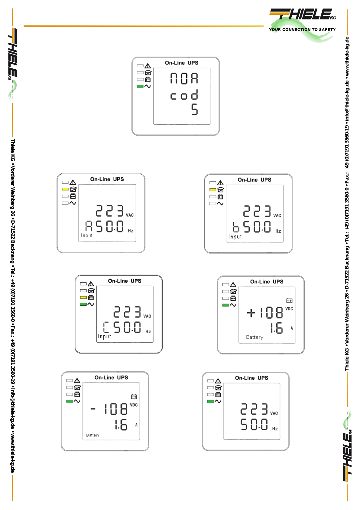
4.2 Start up and Turn off the UPS
4.2.1 Start up operation
1) Turn on the UPS in Line mode:
Once AC Power Cord is plugged in, the UPS will start automatically and the LCD display of
the UPS will be lit on. You may view the data and set parameters on the LCD display as well
as the LED display showing the status of the UPS (NOR Cod. 5 ) and Green LED will be On.
2) Turn on the UPS in Battery Mode (cold start):
YOUR CONNECTION TO SAFETY
Thiele KG • Vorderer Weinberg 26 • D-71522 Backnang • Tel.: +49 (0)7191 3560-0 • Fax.: +49 (0)7191 3560-19 • [email protected] • www.thiele-kg.de
Thiele KG • Vorderer Weinberg 26 • D-71522 Backnang • Tel.: +49 (0)7191 3560-0 • Fax.: +49 (0)7191 3560-19 • [email protected] • www.thiele-kg.de
YOUR CONNECTION TO SAFETY
klick to
www
u-s-v
YOUR CONNECTION TO SAFETY
klick to
www
ACDC-DCDC
YOUR CONNECTION TO SAFETY
klick to
www
SYSTEME
YOUR CONNECTION TO SAFETY
klick to
www
CONTACT
YOUR CONNECTION TO SAFETY
klick to
www
CALLBACK
Ver0217.11.2014 12
Press “On” on the front panel to start the UPS and in the meantime, the LCD display will light
up. You may view the data and set parameters on the LCD display and the LED display of
the UPS will show the latest status of the UPS. Display will show NOR Cod. 6 message,
Yellow LED will be on and an acoustic signal will be emitted every 2 sec. (Battery will be
discharging).
4.2.2 Turn Off operation
1) Turn off the UPS in line mode:
a) Press and hold the OFF key for 2 seconds to turn off the inverter and the UPS is in
Bypass mode now; on the contrary, you may press the hold the OFF key for 2 seconds
in order to Change over back to inverter mode).
b) To shut down (turn off) the UPS completely, you need to turn off the input switch.
2) Turn off the UPS with connecting batteries (no mains):
a) Press and hold the OFF key for 2 seconds to turn off the UPS.
b) After UPS is turned off, all LED and LCD will be extinguished and there is no output.
Nota: When the UPS is turned off from the inverter mode, it will discharge DC Bus and then shut
down completely; therefore, sometimes, it takes more several seconds to complete.
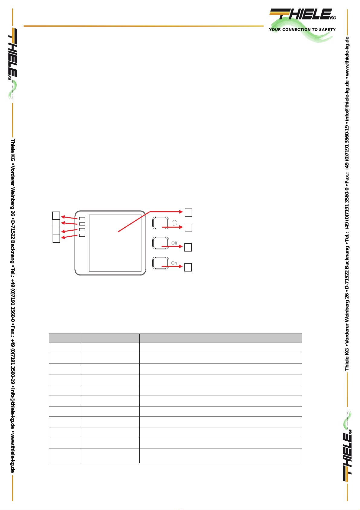
4.3 Control Panel
4.3.1 LED and control panel display
1) ALARM LED (red)
2) BYPASS LED (yellow)
3) BATTERY LED (yellow)
4) INVERTER LED (green)
5) Display LCD
6) ENTER (Scroll button)
7) OFF button
8) ON button
4.3.2 LCD display
NOTE! The display provides more functions than those described in this manual. There are 11
interface available in the LCD display:
ITEM
DESCRIPTION
CONTENT DISPLAYED
01
Code
Operational mode and status
02
Input Phase A
Voltage and Frequency
03
Input Phase B
Voltage and Frequency
04
Input Phase C
Voltage and Frequency
05
Battery +
Voltage and Current
06
Battery -
Voltage and Current
07
Output
Voltage and Frequency
08
Load
Load
09
Temperature
PFC/Internal temperature and Ambient temperature
10
DC Bus Voltage
± DC Bus Voltage
11
Software version &
model
DSP
verson of inverter software version
and UPS model
8
7
6
5
1
2
3
4
YOUR CONNECTION TO SAFETY
Thiele KG • Vorderer Weinberg 26 • D-71522 Backnang • Tel.: +49 (0)7191 3560-0 • Fax.: +49 (0)7191 3560-19 • [email protected] • www.thiele-kg.de
Thiele KG • Vorderer Weinberg 26 • D-71522 Backnang • Tel.: +49 (0)7191 3560-0 • Fax.: +49 (0)7191 3560-19 • [email protected] • www.thiele-kg.de
YOUR CONNECTION TO SAFETY
klick to
www
u-s-v
YOUR CONNECTION TO SAFETY
klick to
www
ACDC-DCDC
YOUR CONNECTION TO SAFETY
klick to
www
SYSTEME
YOUR CONNECTION TO SAFETY
klick to
www
CONTACT
YOUR CONNECTION TO SAFETY
klick to
www
CALLBACK
Ver0217.11.2014 13
When UPS is supplied by the mains the message on display is the following:
01 –Status and operating mode
1) Operating mode are “NOR” or“ECO”.
2) Press “scroll” button, the UPS goes to next page and the display will show the following:
02 –Input phase A 03 –Input phase B
04 –Input phase C 05 - V Bat + / Current
Output
06 - V Bat - / Current 07 -Output
YOUR CONNECTION TO SAFETY
Thiele KG • Vorderer Weinberg 26 • D-71522 Backnang • Tel.: +49 (0)7191 3560-0 • Fax.: +49 (0)7191 3560-19 • [email protected] • www.thiele-kg.de
Thiele KG • Vorderer Weinberg 26 • D-71522 Backnang • Tel.: +49 (0)7191 3560-0 • Fax.: +49 (0)7191 3560-19 • [email protected] • www.thiele-kg.de
YOUR CONNECTION TO SAFETY
klick to
www
u-s-v
YOUR CONNECTION TO SAFETY
klick to
www
ACDC-DCDC
YOUR CONNECTION TO SAFETY
klick to
www
SYSTEME
YOUR CONNECTION TO SAFETY
klick to
www
CONTACT
YOUR CONNECTION TO SAFETY
klick to
www
CALLBACK

Ver0217.11.2014 14
08 -Load 09 - PFC/Internal temp. (up)
and ambient temp. (down)
10 - DC Bus voltage 11 –DSP software version and UPS model
Alarm code (see section 4.6.2)
3) When UPS is charging the battery, the following information are displayed:
Input
Input
Boost charging Floating charging
%ofload
Charge status
YOUR CONNECTION TO SAFETY
Thiele KG • Vorderer Weinberg 26 • D-71522 Backnang • Tel.: +49 (0)7191 3560-0 • Fax.: +49 (0)7191 3560-19 • [email protected] • www.thiele-kg.de
Thiele KG • Vorderer Weinberg 26 • D-71522 Backnang • Tel.: +49 (0)7191 3560-0 • Fax.: +49 (0)7191 3560-19 • [email protected] • www.thiele-kg.de
YOUR CONNECTION TO SAFETY
klick to
www
u-s-v
YOUR CONNECTION TO SAFETY
klick to
www
ACDC-DCDC
YOUR CONNECTION TO SAFETY
klick to
www
SYSTEME
YOUR CONNECTION TO SAFETY
klick to
www
CONTACT
YOUR CONNECTION TO SAFETY
klick to
www
CALLBACK
Ver0217.11.2014 15
4) Pressing “scroll” button, you may circulate all messages from the first one to the last
one then returns back to the first one.
5) All alarm codes are present when abnormal behavior(s) occur(s).
The display value of the above parameter will update within 0.2s.
4.4 Parameters setting
The setting function is controlled by 3 buttons (Enter (, Off ▲,On ▼):
Enter (---goes into the setting page and value adjustment;
Off ▲& On ▼---for choosing different pages.
After the UPS turn ON, press buttons ( & ▲for 3 seconds and then goes into the setting
interface page. After finishing setting the parameter, press “ON” until exiting out of the
current interface.
Note: After entering the setting interface, it will exit when without operation in 30s.
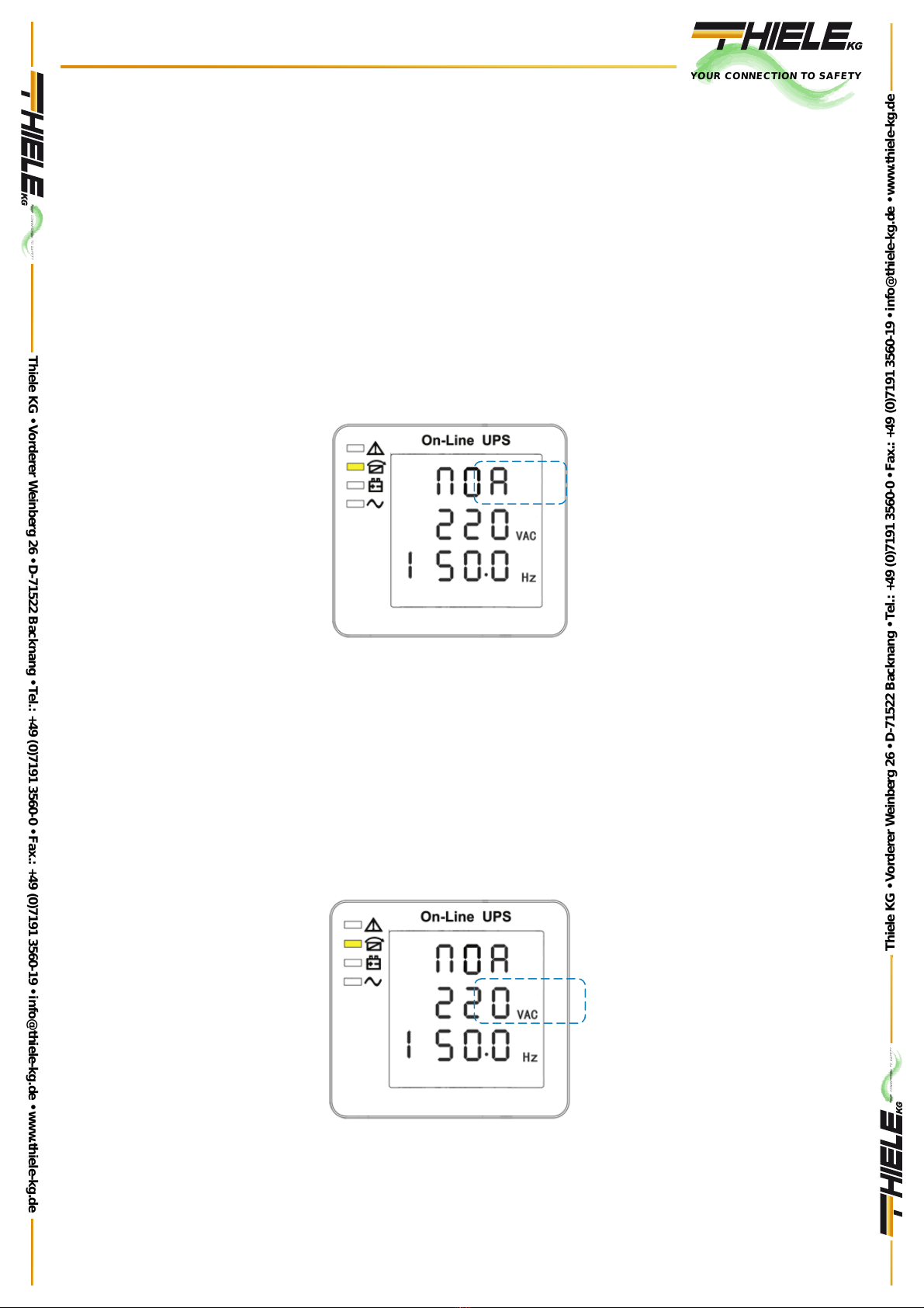
4.4.1 Mode setting
Input
Mode setting
(Note: Inside the broken-line is the flashing part)
After entering the setting menu, it’s mode setting defaulted, and the mode setting line
flashing as in above picture.
ķUse button Enter3to choose different mode. There are 3 different modes for setting:
ECO, PAL, NOR㸹
ĸPress▲or ▼to exit the mode setting
(save the mode setting), and goes to output voltage setting or parallel redundancy quantity
setting
4.4.2 Output voltage setting
Input
Output voltage setting
(Note: Inside the broken-line is the flashing
part.)
YOUR CONNECTION TO SAFETY
Thiele KG • Vorderer Weinberg 26 • D-71522 Backnang • Tel.: +49 (0)7191 3560-0 • Fax.: +49 (0)7191 3560-19 • [email protected] • www.thiele-kg.de
Thiele KG • Vorderer Weinberg 26 • D-71522 Backnang • Tel.: +49 (0)7191 3560-0 • Fax.: +49 (0)7191 3560-19 • [email protected] • www.thiele-kg.de
YOUR CONNECTION TO SAFETY
klick to
www
u-s-v
YOUR CONNECTION TO SAFETY
klick to
www
ACDC-DCDC
YOUR CONNECTION TO SAFETY
klick to
www
SYSTEME
YOUR CONNECTION TO SAFETY
klick to
www
CONTACT
YOUR CONNECTION TO SAFETY
klick to
www
CALLBACK

Ver0217.11.2014 16
When under the mode setting press On▼or when under frequency setting press Off▲, it
goes to the output voltage setting. The output voltage line flashes as in above picture.
xUse button Enter3to choose the different output voltage. There are 3 differe
nt
voltages---220, 230, 240.
xPress▲or ▼to exit the output voltage setting (save the output voltage setting)
and goes to mode setting or frequency setting.
NOTE: When powered by inverter, it is requested to turn off the inverter before setting voltage
and frequency level.
4.4.3 Input/Output frequency setting
Input
Frequency setting
(Note: Inside the broken-line is the
flashing
part.)
When under the output voltage setting press On▼or when under battery capacity setting press
Off▲, it goes to the frequency setting. The frequency line flashes as in above picture.
•Use button Enter
r
to choose the different frequency. There are 2 different
frequency---50/60Hz.
• Press▲or ▼to exit the frequency setting (save the frequency setting) and goes to output
voltage setting or battery capacity setting.
Note: When powered by inverter, it is necessary to turn off the inverter before setting voltage
and frequency level.
4.4.4 Battery capacity setting
Battery
Battery capacity setting
(Note: Inside the broken-line is the flashing part.)
YOUR CONNECTION TO SAFETY
Thiele KG • Vorderer Weinberg 26 • D-71522 Backnang • Tel.: +49 (0)7191 3560-0 • Fax.: +49 (0)7191 3560-19 • [email protected] • www.thiele-kg.de
Thiele KG • Vorderer Weinberg 26 • D-71522 Backnang • Tel.: +49 (0)7191 3560-0 • Fax.: +49 (0)7191 3560-19 • [email protected] • www.thiele-kg.de
YOUR CONNECTION TO SAFETY
klick to
www
u-s-v
YOUR CONNECTION TO SAFETY
klick to
www
ACDC-DCDC
YOUR CONNECTION TO SAFETY
klick to
www
SYSTEME
YOUR CONNECTION TO SAFETY
klick to
www
CONTACT
YOUR CONNECTION TO SAFETY
klick to
www
CALLBACK
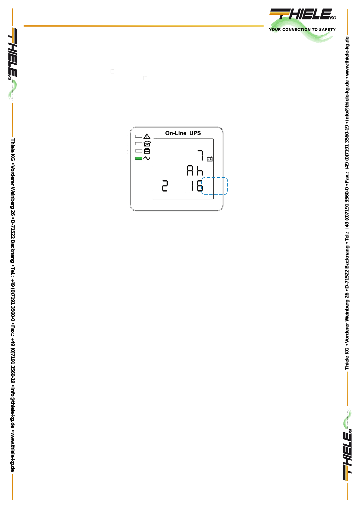
Ver0217.11.2014 17
When under the frequency setting press On▼or when under battery quantity setting press Off▲,
it goes to the battery capacity setting. The battery capacity line flashes as in above picture.
•Use button Enter to choose the different battery capacity. Battery capacity range is
1-200Ah. (Note: long-press of Enter can adjustment battery capacity quickly.)
• Press▲or ▼to exit the battery capacity setting (save the capacity setting) and goes to
frequency setting or battery quantity setting.
4.4.5 Battery quantity setting
Battery
Battery quantity setting
(Note: Inside the broken-line is the flashing
part.)
When under the battery capacity setting press On▼or when under bypass voltage upper
limit setting press Off▲, it goes to the battery quantity setting. The battery quantity line
flashes as in above picture.
xUse button Enter3to choose the different battery quantity. Battery quantity range
is 16,18, 20.
xPress▲or ▼to exit the battery quantity setting (save the battery quantity setting)
and goes to battery capacity setting or bypass voltage upper limit setting.
YOUR CONNECTION TO SAFETY
Thiele KG • Vorderer Weinberg 26 • D-71522 Backnang • Tel.: +49 (0)7191 3560-0 • Fax.: +49 (0)7191 3560-19 • [email protected] • www.thiele-kg.de
Thiele KG • Vorderer Weinberg 26 • D-71522 Backnang • Tel.: +49 (0)7191 3560-0 • Fax.: +49 (0)7191 3560-19 • [email protected] • www.thiele-kg.de
YOUR CONNECTION TO SAFETY
klick to
www
u-s-v
YOUR CONNECTION TO SAFETY
klick to
www
ACDC-DCDC
YOUR CONNECTION TO SAFETY
klick to
www
SYSTEME
YOUR CONNECTION TO SAFETY
klick to
www
CONTACT
YOUR CONNECTION TO SAFETY
klick to
www
CALLBACK
Ver.00
22 Febbraio 2016 18
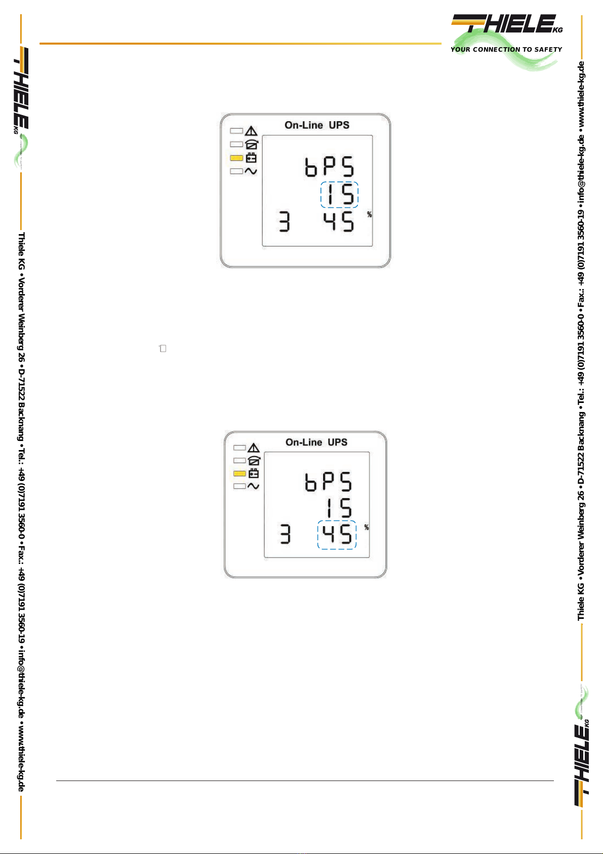
4.4.6 Bypass upper voltage level setting
Bypass upper voltage level setting
(Note: Inside the broken-line is the flashing
part.)
When under the battery quantity setting press On▼or when under bypass voltage lower setting press Off▲, it
goes to the bypass upper limit setting. The bypass upper limit line flashes as in above picture.
•Use button Enter
r
to set the different bypass voltage upper limit. The bypass
voltage upper limit range is 5%,10%,15%,25%(25% .
• Press▲or ▼to exit the bypass voltage upper limit setting (save the bypass voltage upper limit setting)
and goes to battery quantity setting or bypass voltage lower limit setting.
4.4.7 Bypass lower voltage level setting
Bypass lower voltage level setting
(Note: Inside the broken-line is the flashing
part.)
When under the bypass voltage upper limit setting press On▼or when under parallel ID setting press Off▲, it
goes to the bypass lower limit setting. The bypass lower limit line flashes as in above picture. (“-” for negative,
positive does not have any symbol.)
x•Use button Enter ( to set the different bypass voltage lower limit. The bypass voltage lower limit
range is 20%,30%,45%.
x• Press▲or ▼to exit the bypass voltage lower limit setting (save the bypass voltage lower limit
setting) and goes to bypass upper limit setting or parallel ID setting..
YOUR CONNECTION TO SAFETY
Thiele KG • Vorderer Weinberg 26 • D-71522 Backnang • Tel.: +49 (0)7191 3560-0 • Fax.: +49 (0)7191 3560-19 • [email protected] • www.thiele-kg.de
Thiele KG • Vorderer Weinberg 26 • D-71522 Backnang • Tel.: +49 (0)7191 3560-0 • Fax.: +49 (0)7191 3560-19 • [email protected] • www.thiele-kg.de
YOUR CONNECTION TO SAFETY
klick to
www
u-s-v
YOUR CONNECTION TO SAFETY
klick to
www
ACDC-DCDC
YOUR CONNECTION TO SAFETY
klick to
www
SYSTEME
YOUR CONNECTION TO SAFETY
klick to
www
CONTACT
YOUR CONNECTION TO SAFETY
klick to
www
CALLBACK
Ver.00
22 Febbraio 2016 19
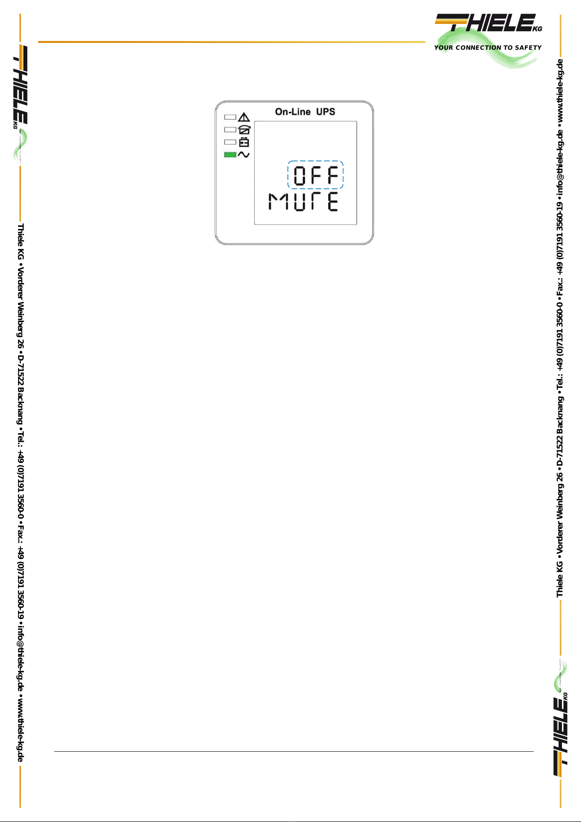
4.4.8 Buzzer mute setting
Buzzers mute setting
(Note˖flashing part in dashed box)
Press ON under bypass voltage lower limit setting or press OFF under the parallel ID setting can enter the
buzzer setting. Now the setting status is flashing as the Figure 14 shows (note: on=mute; off= no mute). When
press, it shows the mute cycle setting, the selection includes ON and OFF. ( Press the up button or down
button can exit the mute setting (save the mute setting status) and switch to bypass voltage lower limit setting
or parallel ID setting (note: when in stand-alone mode, press down button to exit and save the settings, then
the settings is completed for stand-alone unit).
4.5 Working mode and switching
Usually, the UPS should be set to work in AC mode, so it will transfer to battery mode automatically without
interruption when AC fails. When the UPS is overloaded, it will transfer to bypass mode without interruption.
When the inverter is defective or over temperature occurred inside the UPS, the UPS will transfer to bypass
mode if the bypass is normal.
4.5.1 Transfer to Bypass when overload
When the load of UPS is beyond normal range and lasts for the time set, it will transfer to bypass mode and
beeps twice every second, then the load is powered by AC directly. Please decrease the load immediately until
the alarm is eliminated. The UPS will start the inverter after 5 minutes.
4.5.2 Normal Mode to Battery Mode
The UPS will go to battery mode if the AC is failed. The UPS will shut down automatically if batteries are
drained. When AC recovers, the UPS will start the inverter automatically.
4.5.3 Transfer to Bypass when overtemperature
The temperature inside UPS may be high if ambient temperature is high or the ventilation is poor, then the
UPS will go to Bypass mode, fault indicator will be on (red), the LCD will display that the inner temperature is
high, long beeps will come. If so, please cut off the input power of the UPS, move objects that affecting the
ventilation far from the UPS if any or increase the distance between the UPS and the wall. Wait until the UPS
temperature becomes normal then restart it..
4.5.4 Output shortcircuit
When the UPS output is in short circuit, the UPS will cut off the output, fault indictor will be on ( red ), the LCD
will display output is in short circuit, long beeps come. If so, please disconnect the load in short circuit, cut off
the UPS input power and wait for
10mins, the UPS will shut down automatically or press the off button to shut down in after10s. Before
restarting the UPS, please make sure that the short circuit problem has been solved.
YOUR CONNECTION TO SAFETY
Thiele KG • Vorderer Weinberg 26 • D-71522 Backnang • Tel.: +49 (0)7191 3560-0 • Fax.: +49 (0)7191 3560-19 • [email protected] • www.thiele-kg.de
Thiele KG • Vorderer Weinberg 26 • D-71522 Backnang • Tel.: +49 (0)7191 3560-0 • Fax.: +49 (0)7191 3560-19 • [email protected] • www.thiele-kg.de
YOUR CONNECTION TO SAFETY
klick to
www
u-s-v
YOUR CONNECTION TO SAFETY
klick to
www
ACDC-DCDC
YOUR CONNECTION TO SAFETY
klick to
www
SYSTEME
YOUR CONNECTION TO SAFETY
klick to
www
CONTACT
YOUR CONNECTION TO SAFETY
klick to
www
CALLBACK
Ver.00
22 Febbraio 2016 20
4.6 LED and messages on display
This section lists the event and alarm messages that the UPS might display. This section is listed with each
alarm message to help you troubleshoot problems
4.6.1 Operating status
COD
E
STATUS LED
AL
ARM
BY-
PASS
BATTERY
INVERTER
1 Initialized OFF OFF OFF OFF
2 Standby Mode OFF OFF X OFF
3 No Output OFF OFF X OFF
4 By-Pass Mode OFF ON X OFF
5 Mains Mode OFF OFF X ON
6 Battery Mode OFF OFF ON OFF
7Battery
Self-diagnostic OFF OFF ON OFF
8 Inverter in start-
up
OFF X X OFF
9 ECO Mode OFF X X X
10 EPO Mode ON OFF X OFF
11
Maintenance by
-
pass
Mode
OFF OFF OFF OFF
12 Fault Mode ON X X X
Nota: “X” shows that it will determined by other conditions
YOUR CONNECTION TO SAFETY
Thiele KG • Vorderer Weinberg 26 • D-71522 Backnang • Tel.: +49 (0)7191 3560-0 • Fax.: +49 (0)7191 3560-19 • [email protected] • www.thiele-kg.de
Thiele KG • Vorderer Weinberg 26 • D-71522 Backnang • Tel.: +49 (0)7191 3560-0 • Fax.: +49 (0)7191 3560-19 • [email protected] • www.thiele-kg.de
YOUR CONNECTION TO SAFETY
klick to
www
u-s-v
YOUR CONNECTION TO SAFETY
klick to
www
ACDC-DCDC
YOUR CONNECTION TO SAFETY
klick to
www
SYSTEME
YOUR CONNECTION TO SAFETY
klick to
www
CONTACT
YOUR CONNECTION TO SAFETY
klick to
www
CALLBACK
This manual suits for next models
2
Table of contents
Other Thiele UPS manuals


