Thonk Music Thing Modular SimpleEQ Instructions for use

Music Thing Modular
SimpleEQ
Construction Guide
(1206 version)
MTM SimpleEQ 1206 build doc v1.3 Page 1

seful Links
The latest version o this doc and BOM can always be ound at http://thonk.co.uk/documents/eq/
A build thread on the Mu wiggler DIY orum can be ound at this URL
Quickstart
I you're new to building with SMD components, skip to the detailed notes on the next page.
I you're an experienced SMD builder you'll probably want to skip the lengthy notes below, so
here's some things that will probably save you time when you're building this project.
•A detailed BOM can be ound on the last page o this document.
•The op-amps might not have pin 1 indicated by an adjacent dimple/dot in the package, or by
a semi-circular indentation at the end nearest pin 1/pin 8, as is common with through hole
ICs. SMD devices o ten have one o the longer sides with a sloped edge, the other with a
vertical edge. I you have such a device, pin 1 is the le t-most pin o the side with the sloped
ace when the device is pointing upwards. The silk screen on the PCB shows both the
traditional circle next to pin 1 and also a line to indicate the orientation or devices with a
sloped ace. There are pictures on page 19 that show this.
•The suggested build order is to start with the components that have the lowest pro ile &
work upwards, so thats
◦resistors
◦non-polarised capacitors
◦diodes & PTC uses
◦ICs
◦electrolytic capacitors
◦through hole components and panel
•It's suggested that you regularly stop to clean and inspect your work. It's much easier to re-
solder a joint when the board doesn't have the jacks and pots itted.
MTM SimpleEQ 1206 build doc v1.3 Page 2

Recommended Tools
To work with sur ace mount devices, such as those used in this kit, it's a good idea to have the
ollowing tools to hand:
•Soldering iron with a small tip. A 1-2mm chisel or point tip is pre erable.
•Fine gauge solder. Ideally 0.7mm or less.
•Solder wick. This is essential or removing excess solder, especially when soldering the ICs.
•Flux pen. This isn't essential or a kit like this with only two 8-pin IC's, but it does make
soldering some components easier.
•Fine point tweezers. These are essential or handling sur ace mount components.
•Magni ying glass or jewellers Loupe. You'll need some method o inspecting solder joints.
Magni ication o 10x is recommended.
•So t haired brush and PCB cleaner or removing lux residue. The type o cleaner will
depend the on the solder you use. Isopropyl alcohol usually works well.
MTM SimpleEQ 1206 build doc v1.3 Page 3
Introduction to working with Surface Mount
Components
This section isn't meant to be a de initive guide to working with sur ace mount technologies. You'll
ind plenty o tutorials online or that. This is intended to provide some tips as to how to approach
building this kit.
Many sur ace mount components are supplied in tape packaging. For passive components such as
resistors and capacitors, the tape is usually made o cardboard, whilst semiconductors, such as ICs,
transistors, diodes etc will be in a anti-ESD plastic. The tape will probably have a layer o clear
plastic ilm over one side. To remove the device, the easiest way is to care ully peel away the plastic
ilm with a pair o tweezers or ine nosed pliers. Take care when you remove this ilm. These
components are small, and it's easy to lose them i you jolt the tape once the ilm is removed. It's a
good idea to remove them rom the packaging & place them into a bowl or other similarly shaped
container, then pick them rom there as you place them onto the PCB.
MTM SimpleEQ 1206 build doc v1.3 Page 4
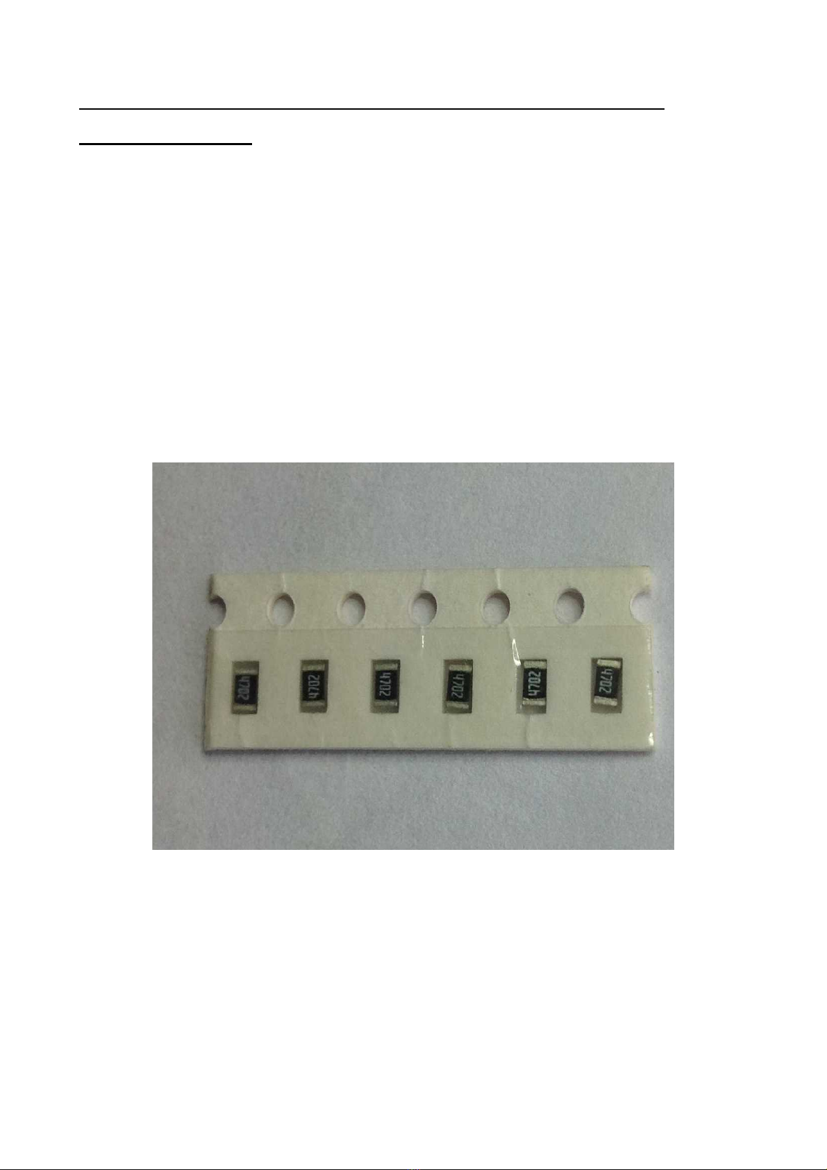
Illustration 1: SMD resistors supplied in tape

MTM SimpleEQ 1206 build doc v1.3 Page 5
Illustration 2: SMD resistors in tape showing plastic cover partially peeled away
Illustration 3: SMD IC's in tape packaging

Install one component type & value at a time. Many o these components are not labelled with their
values, so don't mix them up. Finish one component type & value be ore proceeding to the next.
Don't rush. Regularly inspect your work with the magni ying glass or loupe. Clean your work as
you go. You'll ind it much easier to inspect your work with the solder lux residue removed.
There's many use ul resources online or tutorials on working with sur ace mount devices. The
techniques here suggested here are one way to solder sur ace mount devices. As you become more
amiliar with working with this technology, you may ind other ways o working that you pre er.
So, to the kit ...
MTM SimpleEQ 1206 build doc v1.3 Page 6
The Kit
The PCB:
MTM SimpleEQ 1206 build doc v1.3 Page 7
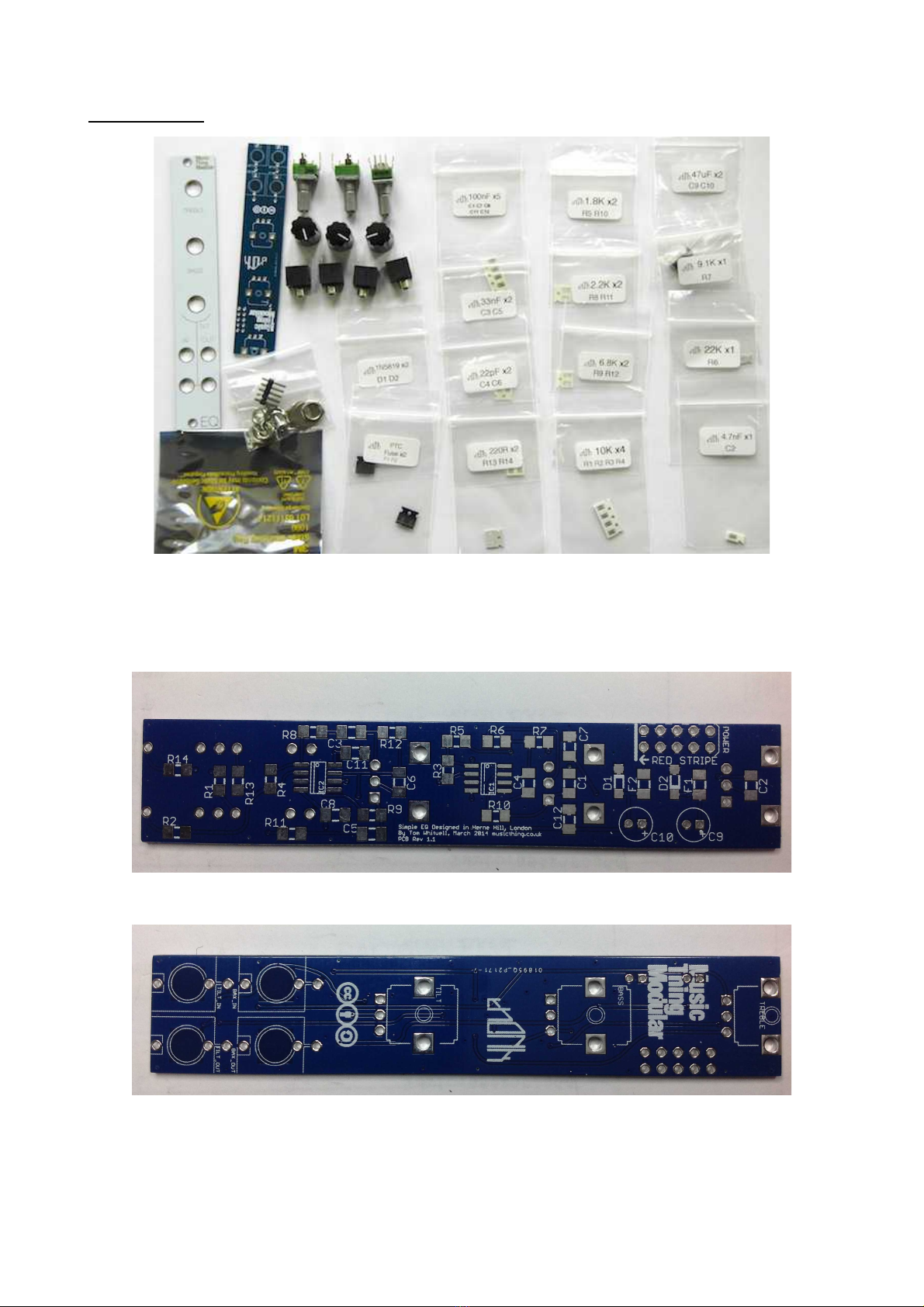
Illustration 5: CB top view
Illustration 6: CB bottom view
Illustration 4: SimpleEQ 1206 kit with white panel

The Build
We'll start with the resistors.
Find the bag that's marked “10K x4 R1 R2 R3 R4” & remove the component tape strip containing
the our resistors. As described above, open up the tape strip by removing the clear ilm cover,
tipping it's contents into a suitable container. One side will probably be a darker colour than the
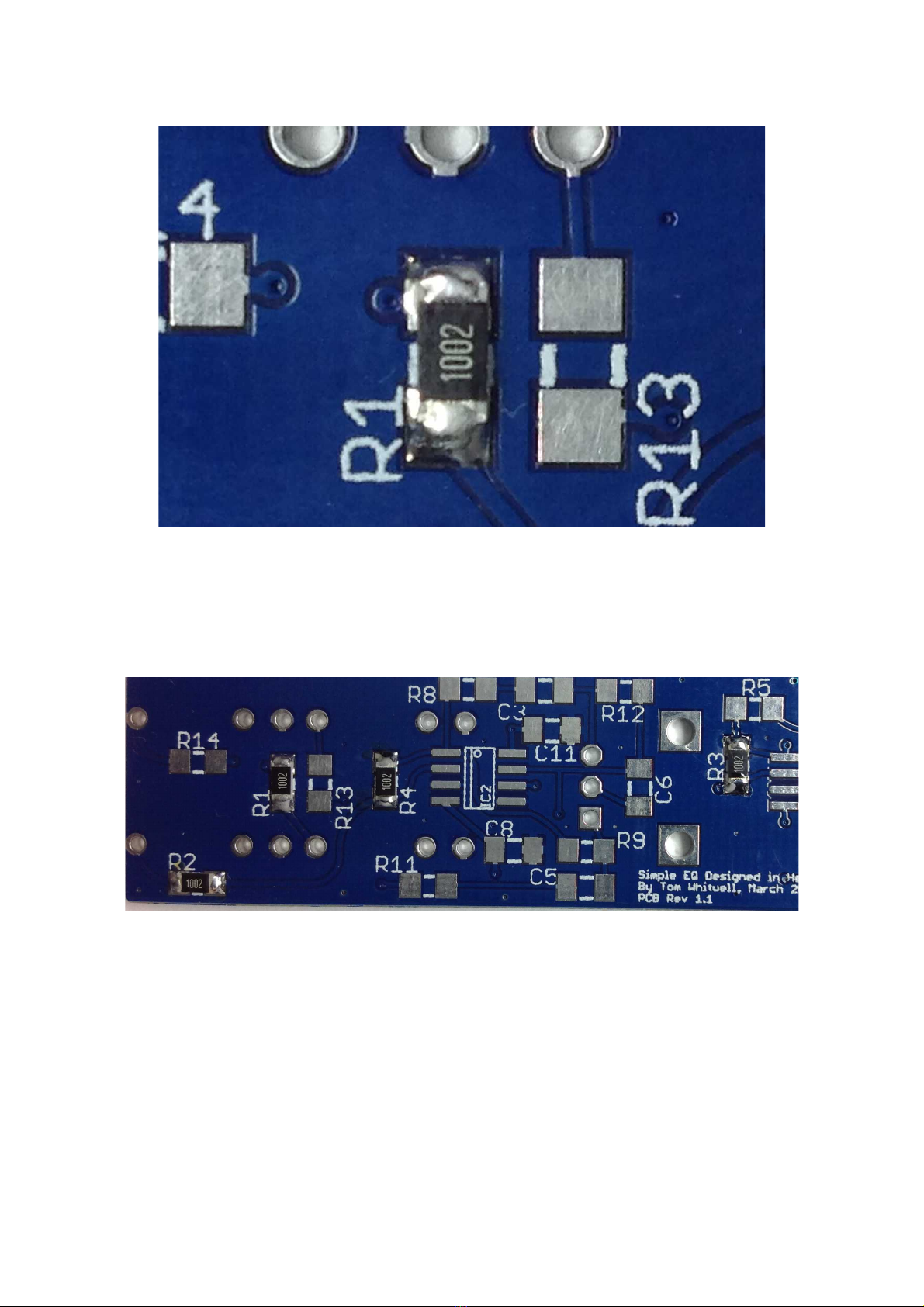
other. The darker side may be marked with the components value. In the image below it's “1002”
(100 x 102 or 10,000 or 10K), though you may also see 10K marked with “103” (10 x 103). Whilst it
doesn't matter which side o the component you have acing upwards, it's good practice to have the
side with the value pointing upwards. As resistors are not polarised it doesn't matter which end o
the resistor is soldered to which pad on the PCB.
Be ore we actually solder the irst o the resistors, lets take some time to actually see how the
resistor will be located on the PCB. Place the PCB on a lat sur ace. Find the location o the irst o
the 10K resistors, R1. It's over towards one side o the board. Notice that the PCB has 2 pads or the
component, and two white silk screen lines between the pads.
MTM SimpleEQ 1206 build doc v1.3 Page 8
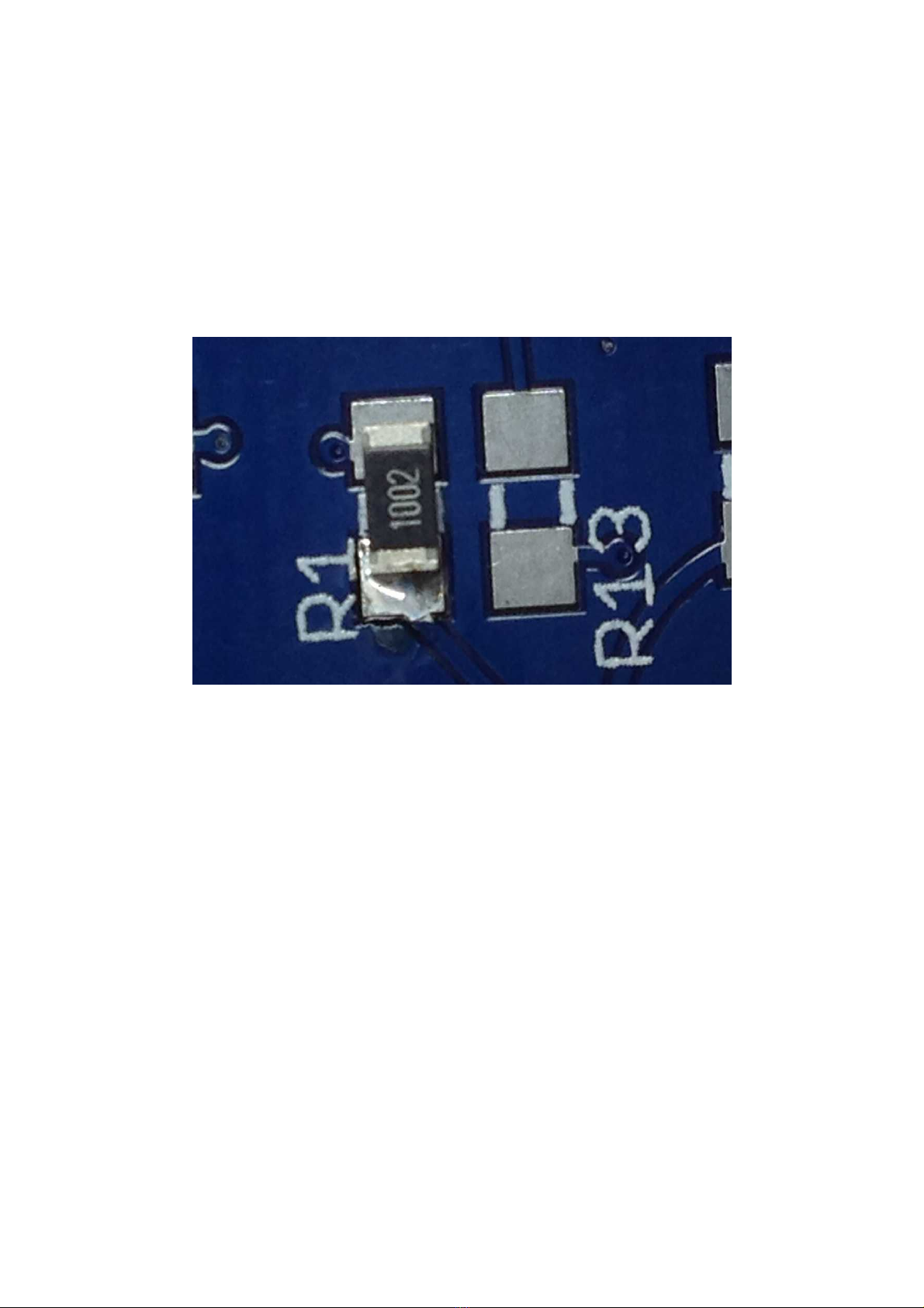
Illustration 8: 10K SMD resistor top view
showing the value “1002”. Illustration 7: SMD resistor bottom view
Illustration 9: SMD resistor pads and silk screen on CB (showing R1)

Pick up one o the resistors using the tweezers, & place the ends o the resistor centrally over the
two pads. Notice how much clearance you have around the outside o the resistor on the pads.
When you solder the resistor in place, you'll want to get similar clearance.
Using the tweezers, place the resistor back in the bowl.
Place the tip o your soldering iron on one o the PCB pads or R1, & immediately apply a small
amount o solder to the pad. Remove the iron tip. You should have a small rounded blob o solder
on the pad.
I you think you've applied too much solder to the pad, you can remove this with solder wick. Place
the wick on top o the blob o solder, apply the tip o the soldering iron brie ly. The wick will soak
up the solder. The wick will probably remove almost all the solder so you'll need to re-apply a small
amount.
MTM SimpleEQ 1206 build doc v1.3 Page 9
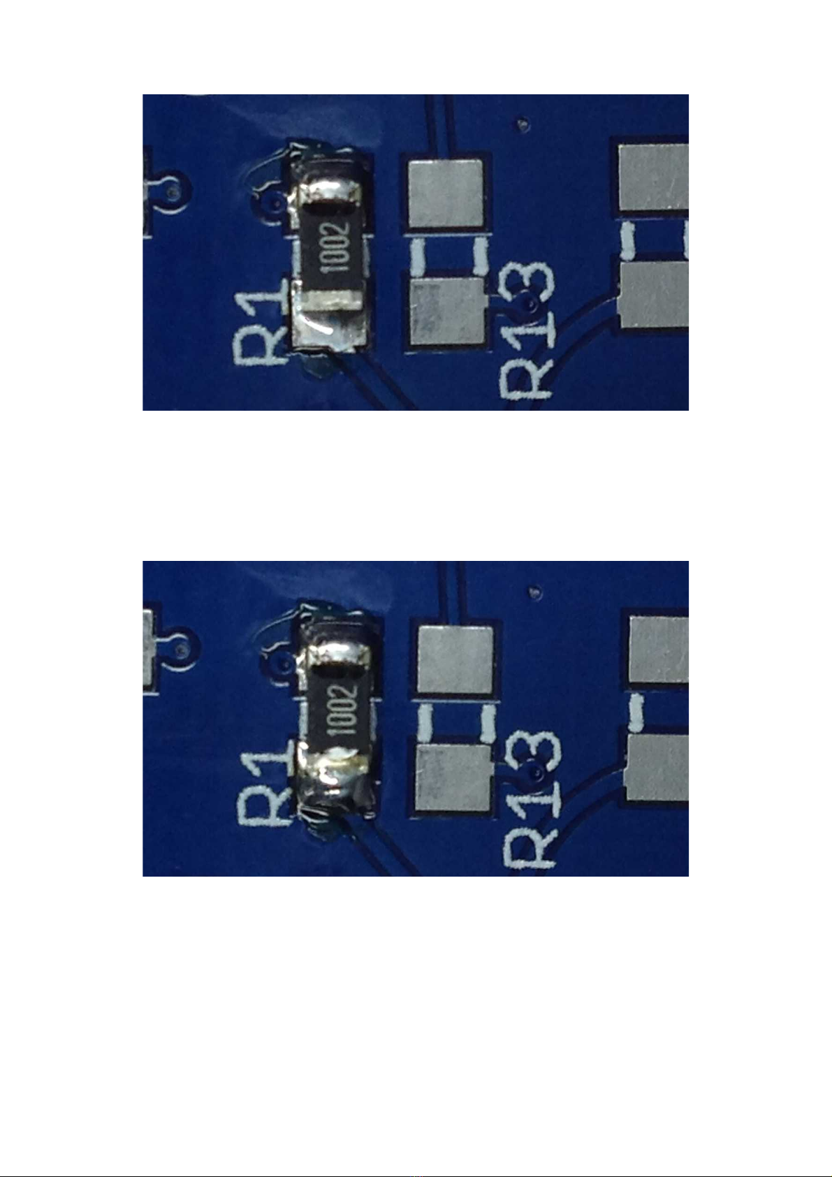
Illustration 10: SMD resistor located centrally on pads
Take one o the resistors in the tweezers, ensuring the side o the resistor with the value marking is
pointing upwards. Re-apply the soldering iron tip to the pad with the solder on it, & quickly slide
one side o the resistor onto the pad, so that the edge o the resistor is lined up on the middle o the
pad, and the resistor is approximately covering equal parts o both pads, as you practiced
previously. Quickly remove the soldering iron tip.
I the resistor is not placed correctly, re-apply the tip o the soldering iron to the pad & the edge o
the resistor & use the tweezers to align the resistor. Remove the iron tip. Try to do this as quickly as
possible. It's much easier to move the resistor with just one pad soldered, so now is the time to get
it's positioning right.
You might think that there isn't a lot o solder on the pad. This is ine, extra will be added once the
other pad is soldered. The component is ixed irmly in place by the solder that is on there.
Now solder the other pad. Place the soldering iron tip on the R1 pad that you didn't solder, resting
the end o the tip up against the side o the resistor, then immediately apply a small amount o
solder to the contact point o the soldering iron tip, the pad & the resistor. The solder will low over
the pad & into the gap between the resistor & the pad. Remove the soldering iron tip. The whole
action should take no more than a couple o seconds.
The resistor should now be located on top o the pads in a similar position to how you practised
earlier.
MTM SimpleEQ 1206 build doc v1.3 Page 10
Illustration 11: resistor soldered to one pad
I you put too much solder on either pad, you can remove this using solder braid. Care ully place
the braid on top o the solder blob, & brie ly apply the soldering iron so the braid soaks up the
solder. I the braid soaks up too much solder, re-apply a small amount o resh solder.
Here's the resistor a ter some additional solder has been applied to the irst pad.
As this is the irst component, now remove any solder lux residue rom around the resistor, using
the so t brush & cleaner appropriate or your solder, as you would do or through hole boards.
Apply a small amount o the cleaner to the resistor & gently brush it to remove the residue. You
may need more than one application o cleaner to ully remove it. Once the residue has been
removed, inspect your soldering using the magni ier. (Removing the lux residue makes the visual
inspection much much easier).
MTM SimpleEQ 1206 build doc v1.3 Page 11
Illustration 12: resistor soldered to both pads
Illustration 13: extra solder applied to the first pad
Now install resistor R2 using the same procedure as you've just done or R1 - Blob o solder on one
pad ; Install the resistor ; Solder the other pad.
Then repeat this or R3 & R4. A ter which the board should look something like this:
Now install the rest o the resistors ...
2 x 220R resistors R13 & R14
2 x 1K8 resistors R5 & R10
2 x 2K2 resistors R8 & R11
2 x 6K8 resistors R9 & R12
1 x 9K1 resistor R7
1 x 22K resistor R6
MTM SimpleEQ 1206 build doc v1.3 Page 12
Illustration 14: R1 after cleaning
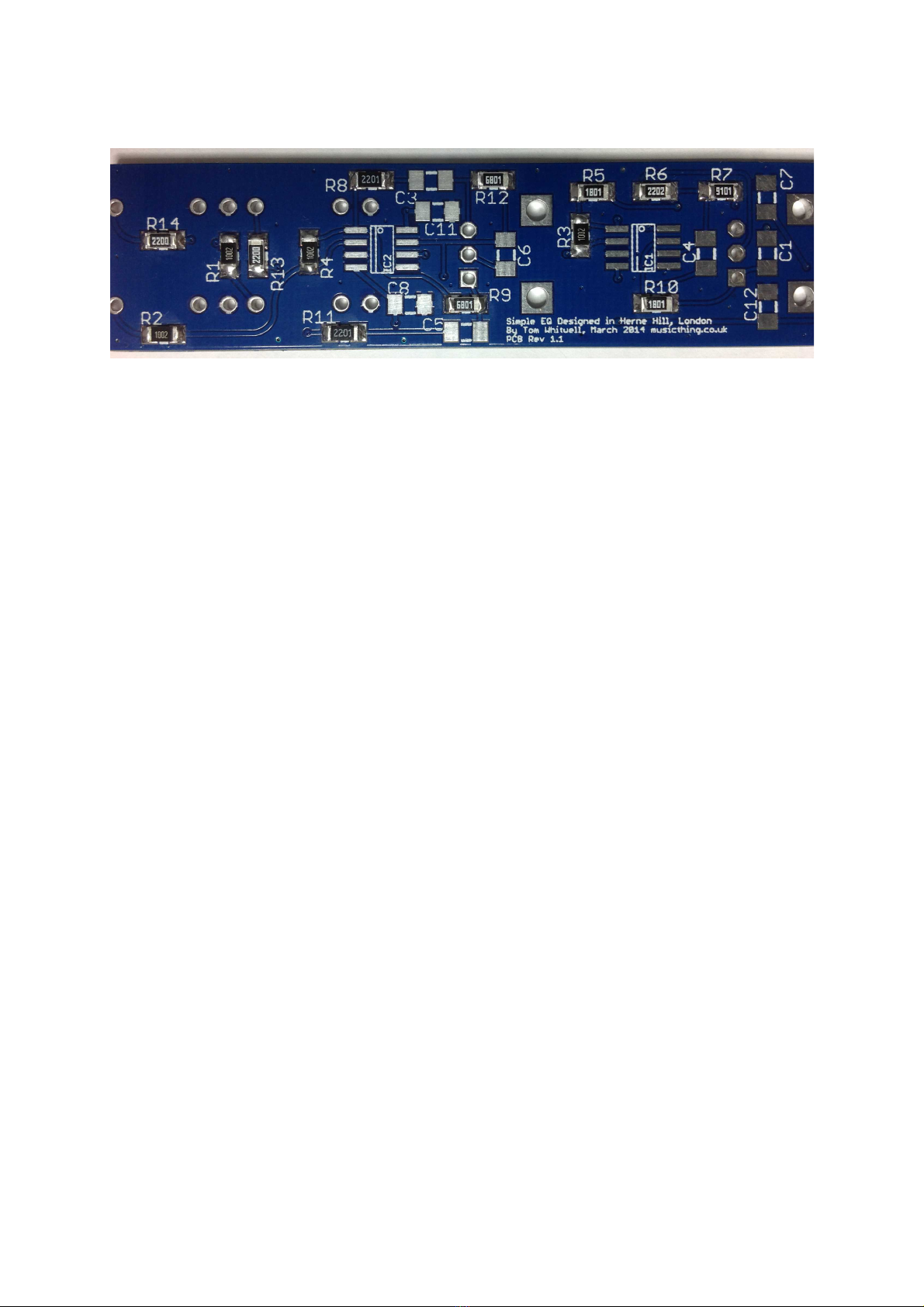
With all the resistors installed, the board should look something like this:
It's a good idea now to clean up the board & then give it an inspection to check everything you've
installed looks OK. Use the same cleaning technique that you used or R1.
Now use a magni ier glass or jewellers loupe to inspect your solder joints. Check that the contact
points on the resistors & the pads on the PCB are covered in solder. Check that the solder doesn't
short on to other tracks or pads. Excess solder can be removed using solder wick as described
previously.
MTM SimpleEQ 1206 build doc v1.3 Page 13

Once you're happy with the placement o the resistors, it's time to progress on to the ceramic
capacitors. As with the resistors, these are non-polarised, meaning they can be oriented in either
direction on the PCB. Unlike the resistors, you'll notice that these are not lat, but have a square
pro ile. With these it doesn't matter which ace is pointing upwards, as you'll see they don't have a
value printed on any ace.
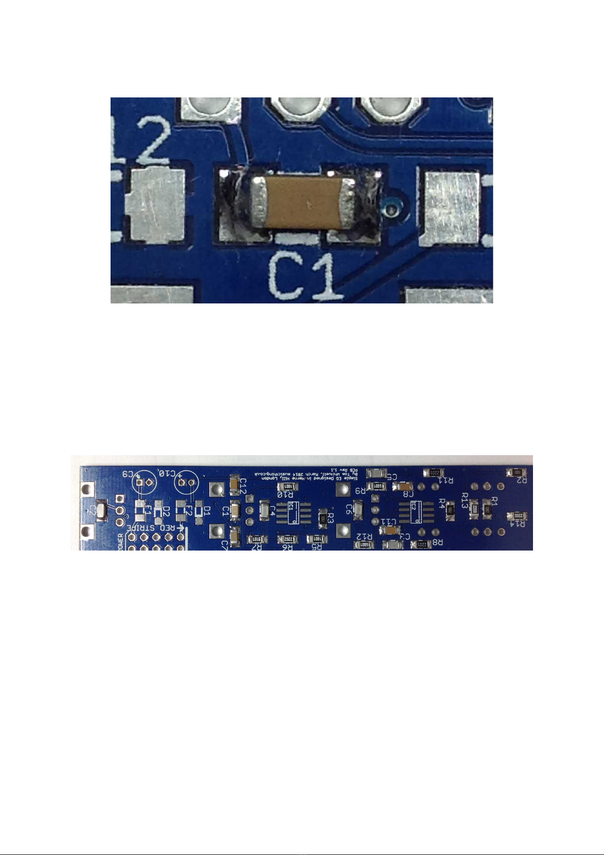
Start with the 5 x 100nF capacitors designated C1, C7, C8, C11, C12. Use exactly the same
procedure to solder these capacitors as you used or the resistors. Again, you might want to o er up
one o the capacitors to it's pads be ore you start to solder, so you get an idea o how the capacitor
will locate on the pads.
MTM SimpleEQ 1206 build doc v1.3 Page 14
Illustration 15: surface mount ceramic capacitor
Illustration 16: ceramic capacitor aligned on CB pads
Now solder the capacitor as you did or the resistors, one pad at a time.
Now install the rest o the ceramic capacitors:
2 x 22pF capacitors C4 & C6
2 x 33nF capacitors C3 & C5
1 x 4.7nF capacitor C2
The board should now look like this:
MTM SimpleEQ 1206 build doc v1.3 Page 15
Illustration 17: 100n ceramic capacitor C1 soldered on both pads
Illustration 18: All resistors and ceramic capacitors soldered
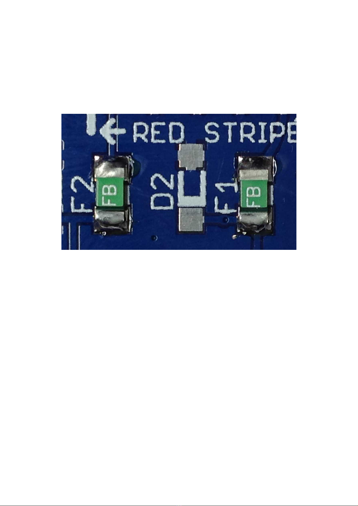
Next install the PTC uses, F1 & F2, which are installed adjacent to the power header. As with the
resistors and capacitors you've installed so ar, these devices are not polarised so they can be
installed in either orientation. Use the same technique or these as or the resistors and the ceramic
capacitors, but try to avoid overheating them, as they can be damaged by excess heat.
Note that the colour and the markings o the uses shipped in the Thonk kit may di er rom the ones
pictured in this build guide.
MTM SimpleEQ 1206 build doc v1.3 Page 16
Illustration 19: TC fuses F1 & F2 installed on the CB
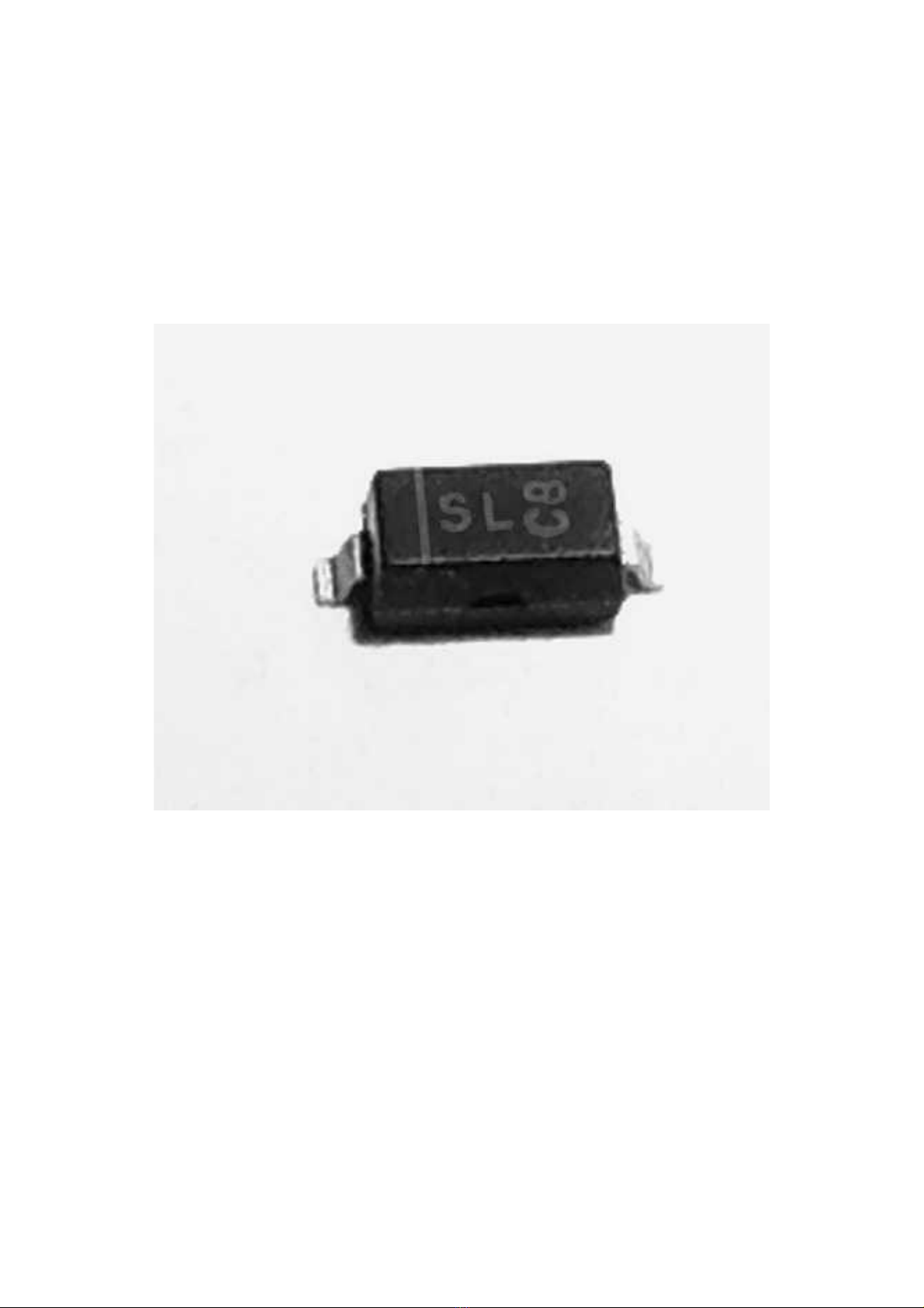
Next, install the two 1N5819 diodes, D1 & D2. Remove the diodes rom the tape, & place them in
the bowl. You'll notice that unlike the resistors and capacitors you've installed already, these diodes
have a metal tab protruding outwards at an angle rom the device. When you solder the diode onto
the PCB, you want these metal tabs in contact with the pads on the PCB.
In addition, unlike the components you've installed up to now, these are polarised devices, meaning
they must be installed on the PCB with the correct orientation. I you look at one closely, you'll
notice a line marked on the top o the package, with the line closer to one o the tabs than the other.
(The line may be aint, so the use o a magni ying glass or loupe will help). This end o the diode
marked with the line is known as the cathode.
MTM SimpleEQ 1206 build doc v1.3 Page 17
Illustration 20: Surface mount diode facing upwards, showing the angled pins, and the
line identifying the cathode end (in this case on the left hand pin)
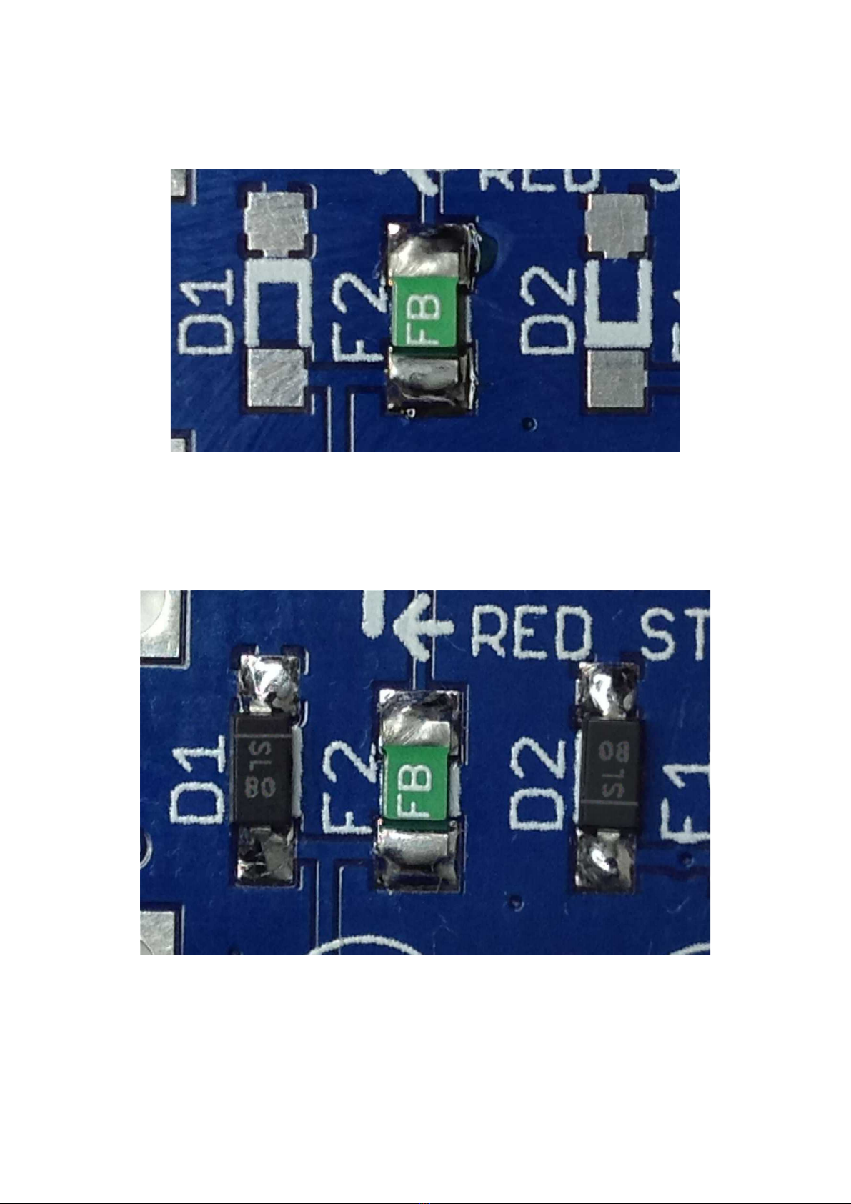
On the PCB, the cathode is indicated by a line in the silk screen adjacent to one o the pads. On this
PCB, the cathode or diode D1 points towards the power header, and diode D2 away rom the
header.
So, now you know which way the diode needs to be installed on the PCB, solder them using the
same technique as the resistors and capacitors.
Now take some time to clean the board as be ore & inspect your soldering on the diodes, capacitors
& uses.
MTM SimpleEQ 1206 build doc v1.3 Page 18
Illustration 22: Diodes D1 & D2 installed, with line identifying cathode, upwards for D1,
downwards for D2
Illustration 21: Surface mount diodes, showing line identifying cathode in silk screen, at top
on D1, bottom on D2

Next we'll do the two IC's, NE5532 dual op-amps. Remove one rom the tape. Take some time to
inspect the device.
Similar to the diodes that you just installed, you'll notice that the IC legs are bent outwards and
downwards, much like the diodes you just installed. As with the diodes, you need to install the
device with these legs in contact with the pads on the PCB.
Unlike through hole IC's, many sur ace mount IC's don't have a dimple or crescent embossed into
the casing to identi y the location o pin 1. Instead, they have a sloped upper edge on the side with
pin 1. The other side has a vertical ace. I you look at the silk screen or the two ICs on your PCB,
you'll notice that it has both the usual dot adjacent to pin 1, but also a second line along one side.
This second line represents the sloped edge. The sloped edge on the IC should be placed along this.
MTM SimpleEQ 1206 build doc v1.3 Page 19
Illustration 23: Surface mount dual op-amp, NE5532
Illustration 24: Surface mount op-amp showing sloped edge on the top left
corner of the packaging.

Again, be ore you start soldering these devices, o er one up to it's destination on the PCB.
Familiarise yoursel with how the device should be orientated, also how the device's pins should sit
on the pads.
Now it's time to solder the irst IC, IC1.
I you have a lux pen, the application o lux to the pads will help soldering the ICs. I you're going
to use one, apply some lux to the pads o both IC1 & IC2.
In a similar way to how you soldered the previous components, place a small blob o solder to one
o the outer pins o IC1.
MTM SimpleEQ 1206 build doc v1.3 Page 20
Illustration 26: NE5532 op-amp located on the pads at IC1 prior to soldering
Illustration 25: CB silk screen for IC1 showing the dot marking the location of pin 1, and
the second line for devices that have a sloping edge on the package
Table of contents
Other Thonk Synthesizer manuals


