Thonk Loose Fruit User manual
!
!
Jan 9th 2019 www.thonk.co.uk 1
God’s Box – Loose Fruit
Eurorack DIY Kit
Instructions
Version 1.1
OVERVIEW
For the most recent version of this
document please visit
https://www.thonk.co.uk/documents/gbox
This document has hi-res images. ZOOM
IN for a closer look
All Thonk kits are sold under our standard Terms and Conditions -
http://www.thonk.co.uk/faq/
DIY INSTRUCTIONS
This document gives detailed instructions that assume you have purchased a
complete kit from www.thonk.co.uk. It also assumes no previous knowledge
of electronics. To learn to solder try http://youtu.be/I_NU2ruzyc4 and the
Adafruit guide to excellent soldering – http://bit.ly/1l77tF4!
Watch and understand that whole YouTube video! If you’re not achieving the
results shown in the video then you need to buy new tools or seek advice.
You will not end up with a working module otherwise.
TOOLS REQUIRED
Soldering iron, snipe nose pliers, wire strippers, small flat head screwdriver
and diagonal cutters AKA snips AKA side-cutters. A Digital Multimeter is
always helpful for checking for bad solder joints and continuity. Thonk sell a
range of inexpensive tools here - http://bit.ly/1jxqF3n

!
!
Jan 9th 2019 www.thonk.co.uk 2
God’s Box – Loose Fruit
Eurorack DIY Kit
Instructions
Version 1.1
SOLDER JOINTS
Your solder joints should look like those shown as ‘OK’ below, they should
have that neat conical shape on BOTH sides of the PCB. If they don’t look
the same on both sides then stop! Work out why from the soldering guides
linked and don’t continue until you are getting those results.
This isn’t just OCD talking, you are very likely to end up with a destroyed,
damaged or defective unit if you’re not hitting that standard.
This photo is from the Adafruit guide to excellent soldering -
http://bit.ly/1jxqF3n and is reproduced under an Attribution-Sharealike
creative commons license - http://creativecommons.org/licenses/by-sa/3.0/

!
!
Jan 9th 2019 www.thonk.co.uk 3
God’s Box – Loose Fruit
Eurorack DIY Kit
Instructions
Version 1.1
LOOSE FRUIT BUILD INSTRUCTIONS
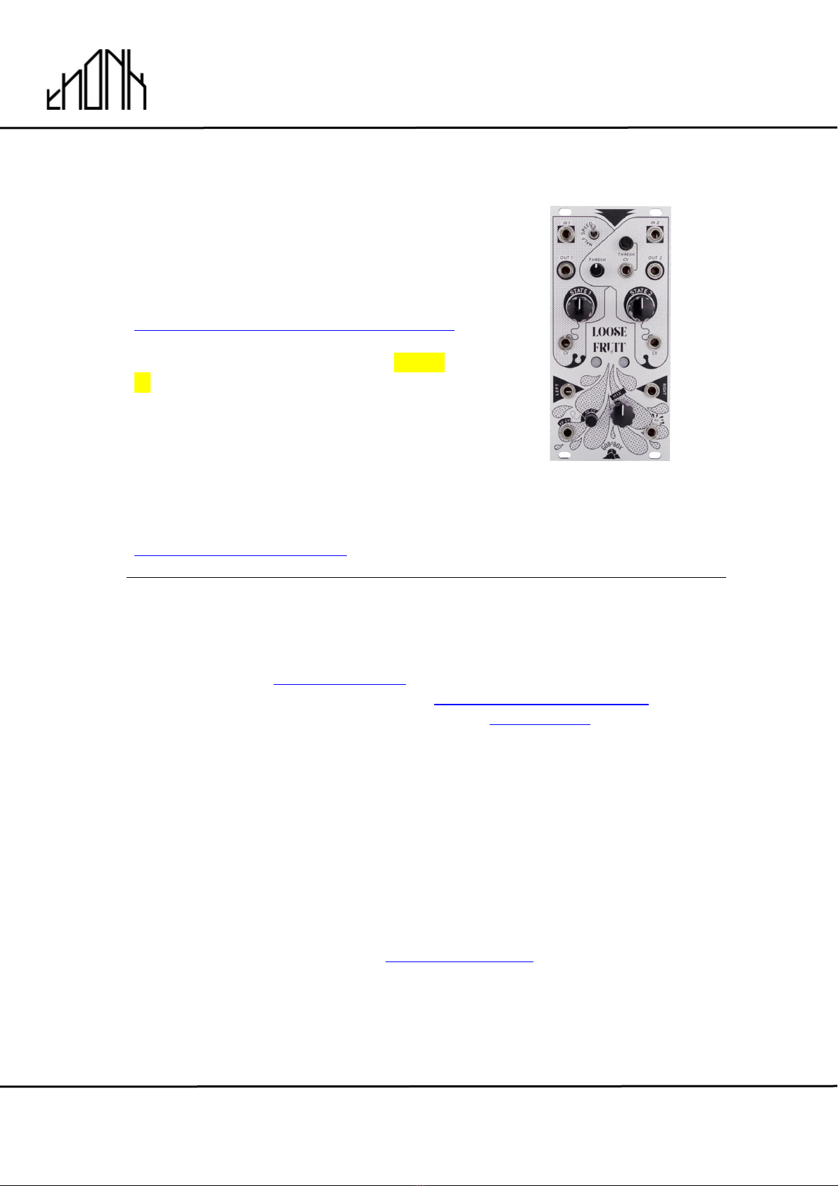
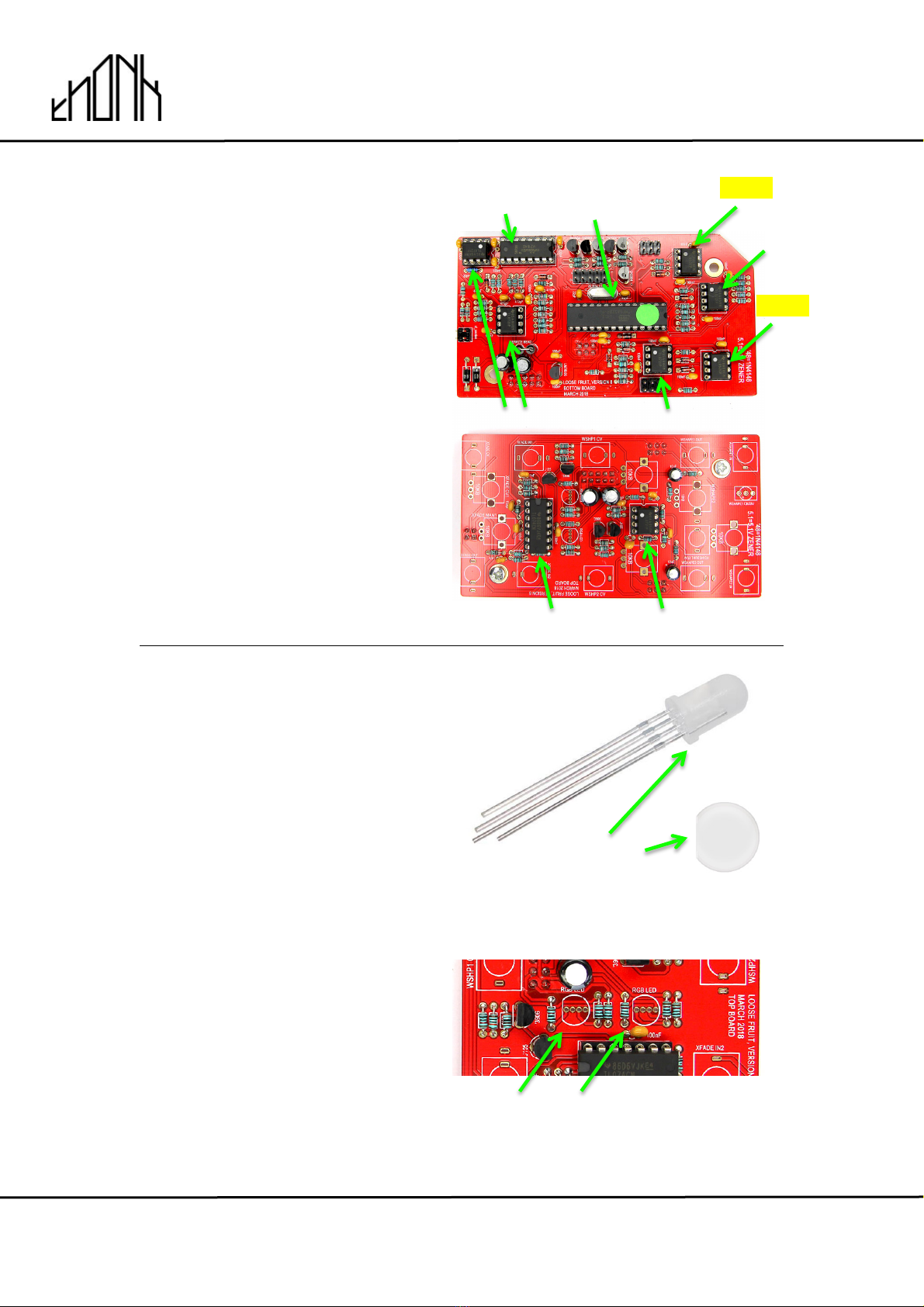
1.
There are two PCBs used in this
build - they are referred to as the
top board and the bottom board.
They can be identified by locating
the text on each PCB as shown.
The bottom board has a diagonal
corner cut off.
2.
Start off by soldering in all the resistors to both the top and bottom boards -
it’s recommended to do this gradually – one value at a time.

!
!
Jan 9th 2019 www.thonk.co.uk 4
God’s Box – Loose Fruit
Eurorack DIY Kit
Instructions
Version 1.1
3.
Next solder in the six 1N4148
diodes. These are labelled on the
PCB as: ’48
Do not confuse these with the
zener diodes which are also
coloured orange and black.
NOTE: Take care with the
orientation of the black stripes on
the diodes – these should match
the thick white lines on the PCB
silkscreen.
NOTE: Do not heat the diodes
excessively or you will damage
them, you should be aiming to
solder quickly and neatly.
4.
Next solder in the three 5.1 Zener
diodes. These are labelled on the
PCB as 5.1
NOTE: Take care with the
orientation of the black stripes on
the diodes – these should match
the thick white lines on the PCB
silkscreen.
5.
Next solder in the two 1N4001
diodes. These are black with a
silver stripe.
NOTE: Take care with the
orientation of the silver stripes
which should match the thick white
lines on the PCB silkscreen.

!
!
Jan 9th 2019 www.thonk.co.uk 5
God’s Box – Loose Fruit
Eurorack DIY Kit
Instructions
Version 1.1
6.
Now take the top board and solder
the two 150pF ceramic capacitors.
7.
Now move to the bottom board
and solder the three 22pF ceramic
capacitors.
8.
Next solder the four 470pF
ceramic capacitors.
9.
Now solder the crystal oscillator.
Orientation does not matter for this
part.

!
!
Jan 9th 2019 www.thonk.co.uk 6
God’s Box – Loose Fruit
Eurorack DIY Kit
Instructions
Version 1.1
10.
Next solder in the IC sockets on
both PCBs. Make sure these
sockets are soldered flush and
perpendicular to the PCB surface.
The notch on each socket should
match the PCB silkscreen as
shown in the pictures.
11.
Next solder the three 1n ceramic
capacitors on the top board
12.
Now solder the twenty-two
100n ceramic capacitors.
!
!
Jan 9th 2019 www.thonk.co.uk 7
God’s Box – Loose Fruit
Eurorack DIY Kit
Instructions
Version 1.1
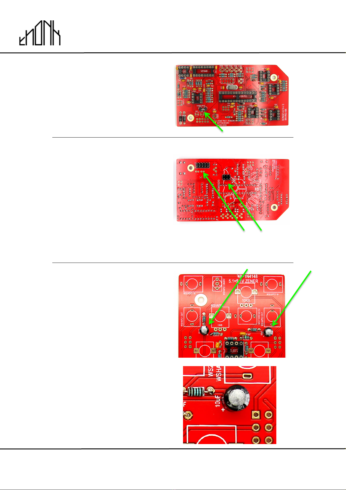
13.
Next solder in the double standing
ferrite bead. Orientation does not
matter for this part.
14.
Next take one of the 2x5 male
headers and one of the 2x3 male
headers. These should be soldered
on the back of the bottom board as
shown.
NOTE! Make sure these headers
are soldered on the opposite side
of all other components on the
bottom board as shown in the
picture.
Bottom Board
15.
Now solder in the two 10uF
Electrolytic Capacitors located on
the top board.
NOTE! Orientation is vital on this
part. The grey stripe and shorter
leg signify the negative side of the
capacitor, the longer lead of the
component should go into the hole
marked + on the PCB.
!
!
Jan 9th 2019 www.thonk.co.uk 8
God’s Box – Loose Fruit
Eurorack DIY Kit
Instructions
Version 1.1
16.
Next solder the four 22uF
Electrolytic Capacitors - there are
two on each PCB.
NOTE! Orientation is vital on this
part. The grey stripe and shorter
leg signify the negative side of the
capacitor, the longer lead of the
component should go into the hole
marked + on the PCB.
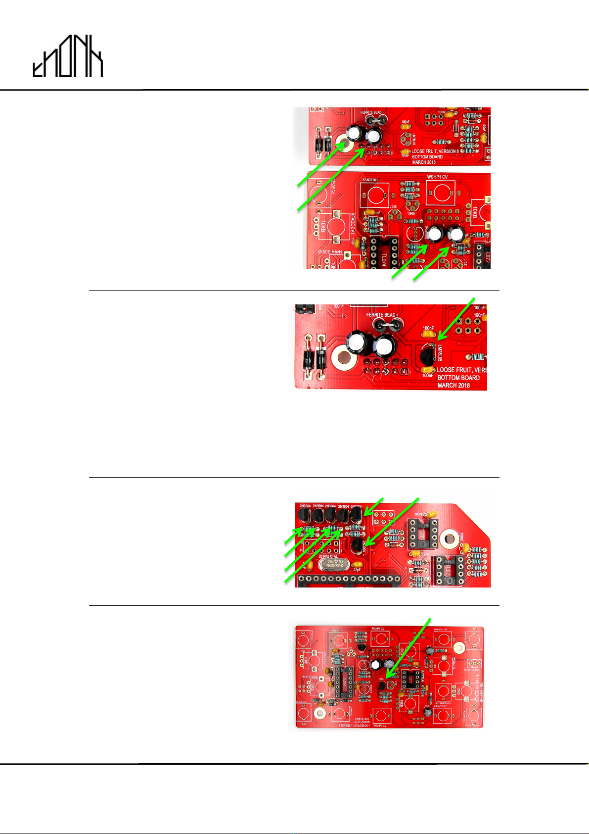
17.
Next solder the single LM78L05 on
the bottom board as shown.
NOTE! Orientation matters – be
sure to match the curve of the
body to the PCB silkscreen.
Do not heat these 3-legged parts
excessively or you will damage them,
you should be aiming to solder quickly
and neatly.
18.
Now solder in the six 2N3904
transistors on the bottom board.
NOTE! Orientation matters – be
sure to match the curve of the
body to the PCB silkscreen.
19.
Now solder the two 2N3906
transistors on to the top board.
NOTE! Orientation matters – be
sure to match the curve of the
body to the PCB silkscreen.
!
!
Jan 9th 2019 www.thonk.co.uk 9
God’s Box – Loose Fruit
Eurorack DIY Kit
Instructions
Version 1.1
20.
Now solder the two J105 JFETs as
shown.
NOTE! Orientation matters – be
sure to match the curve of the
body to the PCB silkscreen.
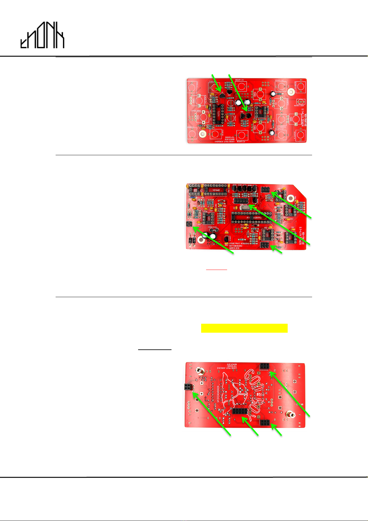
21.
Next place and solder the
remaining male headers on the
bottom PCB - these are placed on
the same side as the resistors and
capacitors as shown.
These should be soldered flush
and perpendicular to the PCB
surface.
Bottom Board
NOTE! Don’t solder these headers to
the other side of the board like the
power header you already soldered!
22.
Now switch to the other PCB and
place but DO NOT SOLDER the
female headers on the top board.
The female headers sit on the
opposite side to all other
components as shown.
Before soldering these headers –
connect them to the male headers
you just soldered on the other
board. Once you have the PCBs
connected nicely with the headers
sitting flush you can then solder
them in place.
Now is also a good time to screw
the hex spacers onto the top PCB.
SWITCH TO OTHER PCB!
Top Board
!
!
Jan 9th 2019 www.thonk.co.uk 10
God’s Box – Loose Fruit
Eurorack DIY Kit
Instructions
Version 1.1
23.
Now disconnect the PCBs and fit
all the ICs into their sockets as
shown.
NOTE! Orientation is vital for all ICs
For the TL052 and TL072 ICs make
sure the black circle on the top
face of the IC is facing the end with
the notch in the IC socket as
pictured.
For all other chips make sure the
notch in the chip is at the side with
the notch in the IC socket.
24.
Next locate the two LEDs.
When viewing the LED bulb from
above or below, you should notice
that one side of the bulb has a
flattened edge.
The flat edge of the bulb must
match the flat edge on the PCB
silkscreen. Taking care of the
orientation - you can place the
LEDs – DO NOT solder them in yet!
TL072
TL074
TL052
TL072
TL052
TL072
Firmware
V2164D
TL072
LED Flat
!
!
Jan 9th 2019 www.thonk.co.uk 11
God’s Box – Loose Fruit
Eurorack DIY Kit
Instructions
Version 1.1
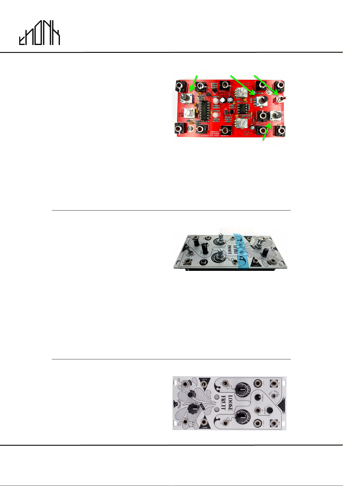
25.
Next place but DO NOT SOLDER
the pots, jacks and switch.
Screw just one of the hex nuts
onto the switch - do not use the
switch washer.
Make sure the taller black trimmer
is correctly placed in the position
labelled WSHAPE2 as pictured.
NOTE: Before soldering the LEDs
it’s recommended to use masking
tape to hold them to the front
panel.
Place the tall black pot where the
PCB is labelled WSHAPE2
26.
We recommend having the domed
section of the LED just poking out
from the panel for the best looking
finish.
Now carefully place the front panel
and secure some of the
components with their nuts to hold
the panel in place.
With the LEDS held in position with
masking tape you can then solder
in all the front panel components.
NOTE! Do not use regular tape as it will
leave a sticky residue on the panel –
only use masking or non-stick tape to
hold the LEDS in place.
27.
Now connect the two PCBs
together - securing the two hex
spacers with screws. Then you can
screw on the rest of the nuts onto
the front panel components and
place the three knobs onto the
pots.
SHORT
TALL
SHORT
SWITCH NUT
!
!
Jan 9th 2019 www.thonk.co.uk 12
God’s Box – Loose Fruit
Eurorack DIY Kit
Instructions
Version 1.1
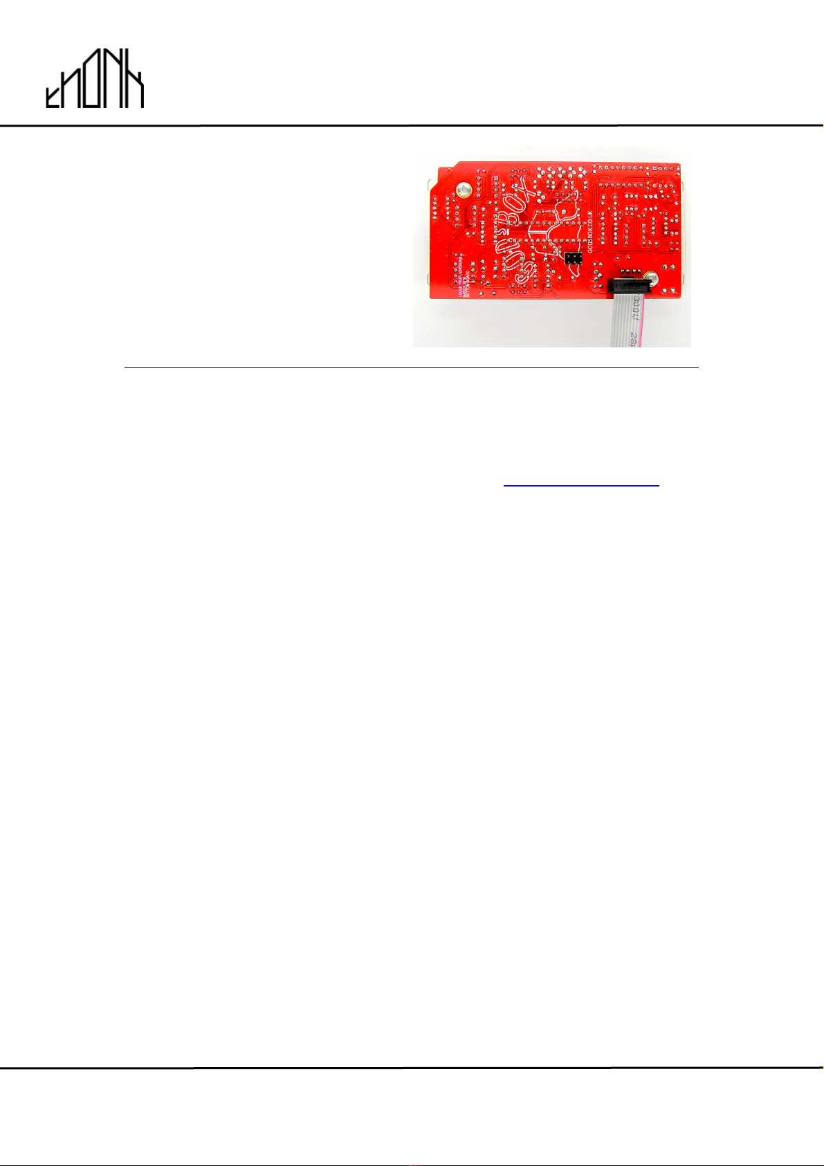
28.
Affix the power cable as shown
with the red stripe down. The red
stripe should always be facing the
PCB text label ‘RED’
29.
The module is now complete. No calibration is required for the Loose Fruit
More info on God’s Box modules can be found at http://godsbox.co.uk
Table of contents
Other Thonk Synthesizer manuals


