THOR GH100-P User manual
Thor Gas Oven
Installation and Operation Instructions
Model: GH100-P, GH100-N, GH101-P, GH101-N, GH102-P, GH102-N, GE 42-P, GE 42-N,
GE 43-P, GE 43-N, GE 44-P, GE 44-N
IMPORTANT FOR FUTURE REFERENCE
Please complete this information and retain this manual for the life of the equipment. For Warranty
Service and/or parts, this information is required.
Model Number Serial Number Date Purchased
WARNING: For your safety, do not store or use asoline or other flammable vapors or
liquids in the vicinity of this or any other appliances. Keep the area free and clear of
combustible.
WARNING :Improper installation, adjustment, alteration, service or maintenance can
cause property dama e, injury, or death. Read the installation operatin and maintenance
instructions thorou hly before installin , or servicin this equipment.
WARNING:Instructions must be posted in a prominent location. All safety precautions
must be taken in the event the user smells as. Safety information can be obtained from
your local as supplier.
15 Bad ally Road, Campbelltown
NSW 2560
Operation Manual 26052015

Contents
Introduction
............................................................................................. 2
Specifications
........................................................................................... 3
General
Pack Contents
Gas Supply Requirements
Dimensions
................................................................................................ 4
Installation
................................................................................................
Installation Requirements
Unpackin
Location
Clearances
Assembly
Gas Connection
Low Flame Settin
Commissionin
Operation
.................................................................................................10
Operation Guide
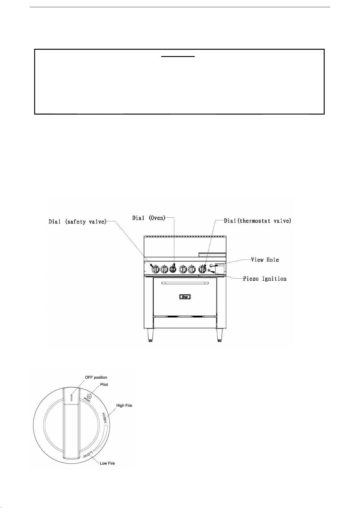
Description of Controls
Li htin the Pilot Burner
Li htin the Main Burner
Cleaning and Maintenance
......................................................................... 13
Routine Maintenance
After Each Use
Daily Cleanin
Weekly Cleanin
Adjustments………………………………………………………………………………………….1
Trouble Shooting
.......................................................................................18
Replacement parts List
........................................................................……24
Explosion Drawing
..............................................................................……2
Spare Parts List
........................................................................................26-29
2
Introduction
We are confident that you will be deli hted with your Thor Gas Oven, and it will become a most valued
appliance in your commercial kitchen.
To ensure you receive the utmost benefit from your new Gas Oven, there are two important thin s you
can do.
Firstly
:
Please read the instruction book carefully and follow the directions iven. The time taken will be well
spent.
Secondly
:
If you are unsure of any aspect of the installation, instructions or performance of your appliance,
contact your dealer promptly. In many cases a phone call could answer your question.
CE Only
:
These instructions are only valid if the country code appears on the appliance. If the code does not
appear on the appliance, refer to the supplier of this appliance to obtain the technical instructions for
adaptin the appliance to the conditions for use in that country.
WARNING:
IMPROPER INSTALLATION, ADJUSTMENT, ALTERATION, SERVICE OR MAINTENANCE CAN CAUSE PROPERTY
DAMAGE, INJURY OR DEATH.
READ THE INSTALLATION, OPERATING AND MAINTENANCE INSTRUCTIONS THOROUGHLY BEFORE INSTALLING OR
SERVICING THIS APPLIANCE.
WARNING:
INSTRUCTIONS TO BE FOLLOWED IN THE EVENT THE USER SMELLS GAS ARE TO BE POSTED IN A PROMINENT
LOCATION. THIS INFORMATION SHALL BE OBTAINED BY CONSULTING THE LOCAL GAS SUPPLIER.
WARNING:
GREAT CARE MUST BE TAKEN BY THE OPERATOR TO USE THE EQUIPMENT SAFELY TO GUARD IT AGAINST RISK OF
FIRE.
•
THE APPLIANCE MUST NOT BE LEFT ON UNATTENDED.
•
IT IS RECOMMENDED THAT A REGULAR INSPECTION IS MADE BY A COMPETENT SERVICE PERSON TO
ENSURE CORRECT AND SAFE OPERATION OF YOUR APPLIANCE IS MAINTAINED.
•
DO NOT STORE OR USE GASOLINE OR OTHER FLAMMABLE VAPOURS OR LIQUIDS IN THE VICINITY OF THIS
OR ANY OTHER APPLIANCE.
•
DO NOT SPRAY AEROSOLS IN THE VICINITY OF THIS APPLIANCE WHILE IT IS IN OPERATION.
CAUTION
:
THIS APPLIANCE IS;
•
FOR PROFESSIONAL USE AND IS TO BE USED BY QUALIFIED PERSONS ONLY.
•
ONLY QUALIFIED SERVICE PERSONS ARE TO CARRY OUT INSTALLATION, SERVICING AND GAS CONVERSION
OPERATIONS.
•
COMPONENTS HAVING ADJUSTMENTS PROTECTED BY THE MANUFACTURER SHOULD NOT BE ADJUSTED BY
THE USER/OPERATOR.
•
DO NOT OPERATE THE APPLIANCE WITHOUT THE LEGS SUPPLIED FITTED.

3
Specifications
General
Commercial heavy duty oven.
Pack Contents
The followin is included:
Thor Gas Oven
2pcs racks
4pcs Feet
Instruction Manual
Gas Supply
Requirements
Natural Gas Propane
GH100-N
GH101-N
GH102-N
GH100-P
GH101-P
GH102-P
Single burner Heat Input
32.5 MJ 32.5 MJ 32.5 MJ 32.5 MJ 32.5 MJ 32.5 MJ
Oven burner
26.5MJ 26.5MJ 26.5MJ 28MJ 32.5 MJ 32.5 MJ
Heat Total
156.5 MJ 221.5 MJ 189MJ 158 MJ 227.5 MJ 195MJ
Burner Operating
1.0 kPa 2.75 kPa
Supply Pressure
1.0 kPa 2.75 kPa
Gas Connection
¾” BSP Male ¾” BSP Male
Natural Gas Propane
GE 42-N
GE 43-N GE 44-N
GE 42-P GE 43-P
GE 4 -P
Single burner Heat Input
32.5 MJ 32.5 MJ 32.5 MJ 32.5 MJ 32.5 MJ 32.5 MJ
Oven burner
26.5MJ 26.5MJ 26.5MJ 28MJ 32.5 MJ 32.5 MJ
Heat Total
91.5 MJ 156.5 MJ 124MJ 93 MJ 162.5MJ 130MJ
Burner Operating
1.0 kPa 2.75 kPa
Supply Pressure
1.0 kPa 2.75 kPa
Gas Connection
¾” BSP Male ¾” BSP Male
The burner operatin pressure is to be measured at the as control valve outlet test point with two burner
operatin at ‘Hi h’ settin . The operatin pressure is ex-factory set, throu h the appliance re ulator and not
to be adjusted, apart from when carryin out as conversion, if required. (Refer to the ‘Gas Conversion’
section for details).
Minimum input of burner: Open burner: 23MJ for NG
‘U’ burner: 21MJ for NG
Size of the pan: The smallest pan for open burner is 100mm;
The bi est pan for open burner is 300mm.
The hi hest temperature of riddle plate is 290℃(thermostat valve)
The hi hest temperature of riddle plate is 390℃(safety valve).The burner operatin pressure is to be
measured at the as control valve outlet test point with one burner operatin at ‘Hi h’ settin . The operatin
pressure is ex-factory set, throu h the appliance re ulator and not to be adjusted.

4
Dimensions
Dimensions for Freestanding Oven
GH104-P / GH104-N
Model Number
Exterior Dimensions (Millime
ters)
A
B
C
D
E
F
H
L
TR-4F
GH100-P / GH100-N
610 835 680 750 1175 940
TR-0-G24F(T)
GE542-P/GE542-N
610 835 610 680 750 510 1175 940
TR-6F
GH101-P / GH101-N
915
835
680
750
1175
940
TR-4F-G12F(T)
GH102-P / GH102-N
915
835
305
680
750
510
1175
940
TR-2F-G24F(T)
GE543-P/GE543-N
915
835
610
680
750
510
1175
940
TR-0-G36F (T)
GE544-P/GE544-N
915
835
915
680
750
510
1175
940
Views

5
Installation
Installation Requirements
NOTE:
•
It is most important that this appliance is installed correctly and that operation is correct before
use. Installation shall comply with local gas, health and safety requirements.
•
This appliance shall be installed with sufficient ventilation to prevent the occurrence of
unacceptable concentrations of substances harmful to health.
Our Gas Ovens are desi ned to provide years of satisfactory service and correct installation is essential to
achieve the best performance, efficiency and trouble-free operation.
This appliance must be installed in accordance with National installation codes and in addition, in accordance
with relevant National / Local codes coverin as and fire safety.
Australia:
AS 5601/AG 601 (to be AS 5601)- Gas Installations
New Zealand:
NZS 5261 - Gas Installation.
United Kingdom:
Gas Safety (Installation and Use) Re ulations 1998
BS 6173-Installation of Caterin Appliances.
BS 5440-1&2 Installation Fluein & Ventilation.
Ireland:
IS 820-Non Domestic Gas Installations.
Installations must be carried out by qualified persons only. Failure to install equipment to the relevant
codes and manufacturer’s specifications shown in this section will void the warranty.
Components havin adjustments protected by the manufacturer are only to be adjusted by an authorized
service a ent. They are not to be adjusted by the installation person.
Step 1: Unpacking
IMMEDIATELY INSPECT FOR SHIPPING DAMAGE
All containers should be examined for dama e before and durin unloadin . The frei ht carrier has assumed
responsibility for its safe transit and delivery. If dama ed equipment is received, either apparent or
concealed, a claim must be made with the deliverin carrier.
Apparent dama e or loss must be noted on the frei ht bill at the time of delivery. The frei ht bill must then
be si ned by the carrier representative (Driver). If the bill is not si ned, the carrier may refuse the claim.
The carrier can supply the necessary forms.
A request for inspection must be made to the carrier within 15 days if there is connected dama e or loss
that is not apparent until after the equipment is uncreated. The carrier should arran e an inspection. Be
certain to hold all contents plus all packin material.

6
Installation (Continued)
1. Remove screws and disassemble the top and side wood packa in .
2. Remove plastic wrap and set aside the flue box.
3. Remove the Gas Oven from the pallet for installation.
Step 2a: Install the Legs
A set of four le s is packed with units ordered with le s. (For units ordered with casters (option), o to step 2b).
A threaded le pad is fastened to the base frame at each corner. Each le has a correspondin matin thread.
The le can be adjusted to overcome a sli htly uneven floor.
1. Raise unit sufficiently to allow le pads and le s to be attached. For safety, “shore up” and support the unit
with an adequate blockin arran ement stron enou h to support the load.
2. Attach the four le pads to the bottom of the ran e usin the lock washers and machine screws. The
mountin holes are pre-drilled and threaded.
3. Screw the le s into the holes in the centers of the le pads.
4. Lower unit ently onto a level surface. Never drop or allow the unit to fall.
5. Use a level to make sure that the ran e surface is level. The le s can be screwed in or out to lower or raise
each corner of the ran e.
6. Go on to installation Step 3.
7
Installation (Continued)
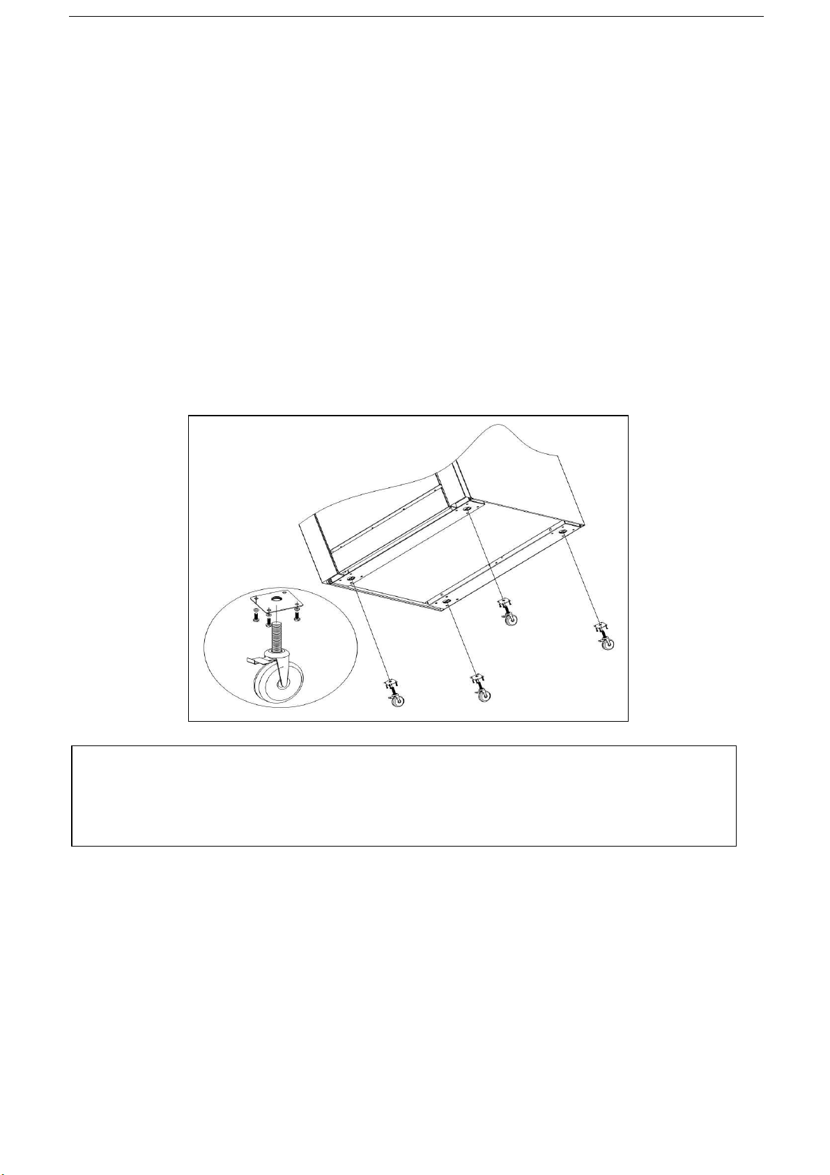
Step 2b: Install Casters (options)
A set of four casters is packed with units ordered with casters (instead of le s).
A threaded le pad is fastened to the base frame at each corner. Each caster as a correspondin matin
thread. The caster can be adjusted to overcome a sli htly uneven floor. Casters are provided with a Zerk fittin
for proper lubrication when required.
1. Raise unit sufficiently to allow le pads and casters to be attached. For safety, “shore up” and support the
unit with an adequate blockin arran ement stron enou h to support the load.
2. Attach the four le pads to the bottom of the ran e usin the lock washers and machine screws. The
mountin holes are pre-drilled and threaded.
3. Screw the caster into the holes in the centers of the le pads. Install the casters that have a lockin brake
under the front of the unit.
4. Lower unit ently onto a level surface. Never drop or allow the unit to fall.
5. Use a level to make sure that the ran e surface is level. The casters can be screwed in or out to lower or
raise each corner of the ran e. After the unit has been leveled, ti hten the lock nuts.
6. Secure the restrainin -device bracket to a wall stud located as close as possible to the appliance connector
inlet and outlet connections. Use four screws.
NOTICE
Adequate means must be provided to limit the movement of the appliance without dependin on the
connector and the quick-disconnect device or its associated pipin to limit the appliance movement.
The restrainin means should be attached to a frame member on the back of the unit.
8
Installation (Continued)
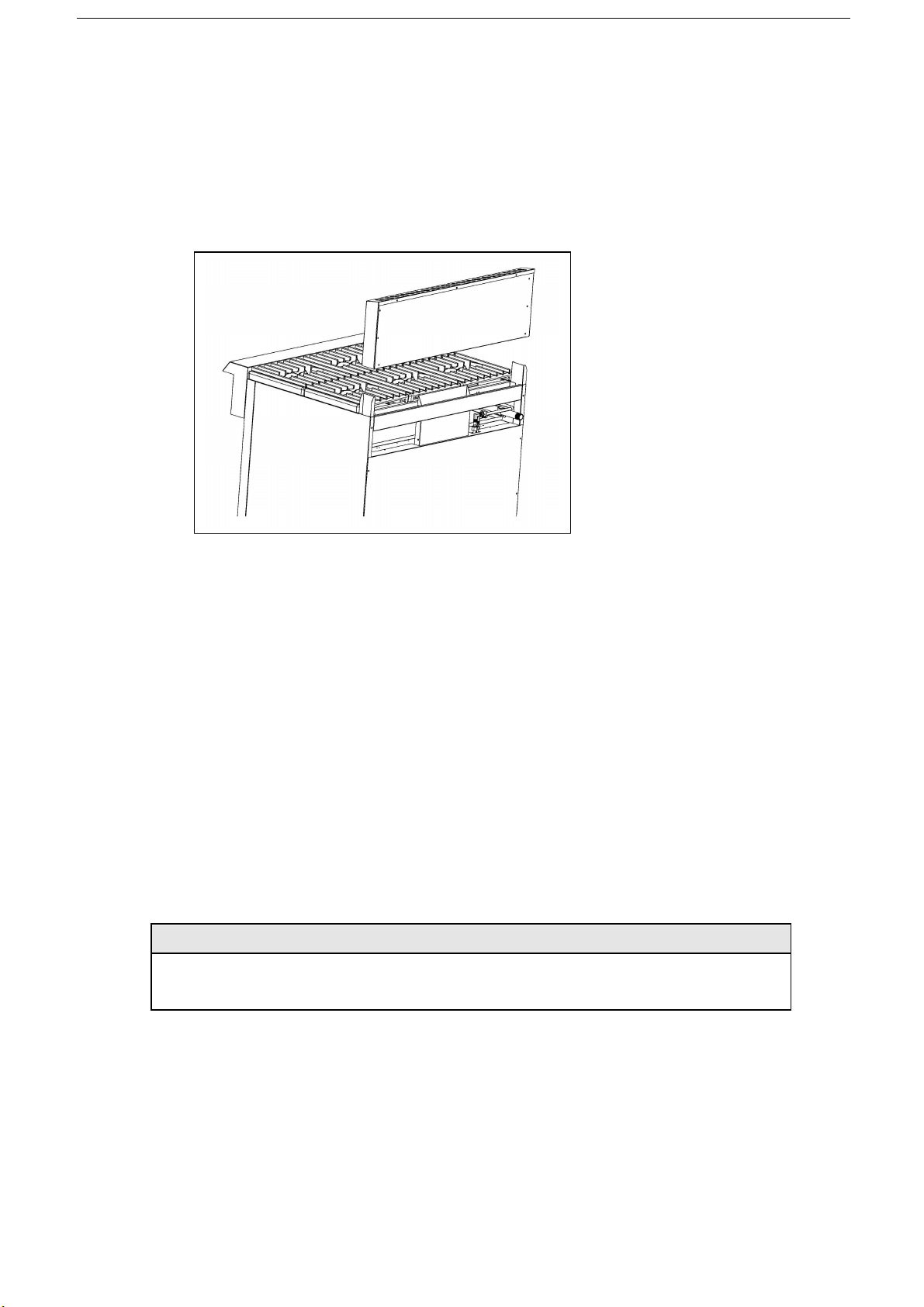
Step 3: Attach Flue Riser
1. Place the flue riser assembly on the ran e as shown on the appropriate dia ram below.
2. Slide the flue riser assembly over the bayonets until it bottom out, as shown below.
3. Secure ends of flue riser assembly with two M6 hex head bolts, flat washers and lock-washers
Sin le-Oven Models
Location
1. Installation must allow for a sufficient flow of fresh air for the combustion air supply.
2. Installation must include adequate ventilation means, to prevent dan erous build-up of combustion
products.
3. Any as burnin appliance requires adequate clearance and ventilation for optimum and trouble-free
operation. The minimum installation clearances shown below are to be adhered to.
4. Position the appliance in its approximate workin position.
5. All air for burner combustion is supplied from underneath the unit. The le s must always be fitted
and no obstructions placed on the underside or around the base of the unit, as obstructions will
cause incorrect operation and / or failure of the appliance.
6. Components havin adjustments protected by manufacturer are only allowed to be adjusted by an
authorized service a ent. They are not to be adjusted by the installation person.
Clearances
NOTE: Only non-combustible materials can be used in close proximity to this appliance.
Combustible
Surface
Non Combustible
Surface
Left / Ri ht Hand Side
Rear
355mm
250mm
0mm
0mm
Assembly
NOTE:
•
This appliance is assembled before delivery except feet.
•
This appliance is fitted with adjustable feet to enable the appliance to be positioned securely and
level. This should be carried out on completion of the as connection. Refer to the ‘Gas
Connection’ section.
•
IM will be stated that the appliance shall be installed in such a way that side body surfaces are not
accessible in the installed position.

9
Installation (Continued)
Gas Connection
NOTE: ALL GAS FITTING MUST ONLY BE CARRIED OUT BY A QUALIFIED PERSON.
1. The Gas Ovens do not require an electrical connection, as they function totally on the as
supply only.
2. It is essential that the as supply is correct for the appliance to be installed and that
adequate supply pressure and volume are available. The followin checks should
therefore be made before installation:-
a. Gas Type required for the appliance is shown in the ratin label. Check that this is correct for
the as supply the appliance is bein installed for. The as conversion procedure is detailed
in this manual.
b. Supply Pressure required for this appliance is shown in the ‘Gas supply requirements’ section
of this manual. Check the as supply to ensure adequate supply pressure exists.
c. Input Rate of this appliance is stated on the Ratin label .The input rate should be checked
a ainst the available as supply line capacity. Particular note should be taken if the appliance is
bein added to an existin installation.
NOTE: It is important that adequately sized pipin runs directly to the connection joint on the
appliance with as few tees and elbows as possible to ive maximum supply volume.
NOTE: Ensure the re ulator is converted to the correct as type that the appliance will operate on. The
re ulator outlet pressure is fixed ex-factory for the as type .
3. Correctly locate the appliance into its final operatin position and usin a spirit level, adjust
the le s so that the unit is level and at the correct hei ht.
4. Connect the as supply to the appliance throu h the re ulator. A suitable jointin compound
which resists the breakdown action of propane must be used on every as line connection,
unless compression fittin s are used.
5. Check all as connections for leaka es.
WARNING:
DO NOT USE A NAKED FLAME TO CHECK FOR GAS
LEAKAGES
.
6. Check that the as operatin pressure.
7. Turn off the mains as supply and bleed the as out of the appliance as lines.
8. Turn on the as supply and the appliance.
9. Verify the operatin pressure remains correct.
Low Flame Setting
Check the low flame settin by li htin the oven and heatin to a set temperature. When the set temperature
has been reached the thermostat will reduce the oven burner flame to its low rate. Check that rapid closin of
the oven door does not extin uish the flame. If necessary, adjustment to the low flame settin is made by
removin the oven knob and turnin the bypass adjustment screw (Clockwise to decrease and anti-clockwise
to increase the flame). Care should be taken, as the appliance will become hot durin commissionin .
Note: To obtain the above burner pressures adjust the re ulator as supplied with the unit. When the correct
operatin pressure has been obtained then re-assemble unit.
WARNING: Failure to check and set the oven low flame setting may initiate an un-necessary
service call due to the oven burner "going out".

10
Commissioning
1. Before leavin the new installation;
a. Check the followin functions in accordance with the operatin instructions specified in the
‘Operation’ section of this manual.
•
Li ht the Pilot Burner.
•
Li ht the Main Burner.
•
Turnin 'Off' the Main Burner/Pilot.
b. Ensure that the operator has been instructed in the areas of correct li htin , operation, and
shutdown procedure for the appliance.
2. This manual must be kept by the owner for future reference and a record of the Date of Purchase,
Date of Installation and the Serial Number of the Appliance must be recorded and kept with this
manual. (These details can be found on the Ratin label, refer to the ‘Gas Connection’ section).
NOTE: If for some reason it is not possible to et the appliance to operate correctly, shut off the as
supply and contact the supplier of this appliance.
11
Operation
Operation Guide
CAUTION:
•
THIS APPLIANCE IS FOR PROFESSIONAL USE AND IS ONLY TO BE USED BY QUALIFIED PEOPLE.
•
ONLY QUALIFIED SERVICE PERSONS ARE TO CARRY OUT INSTALLATION, SERVICING OR GAS CONVERSION
OPERATIONS.
•
COMPONENTS HAVING ADJUSTMENTS PROTECTED (E.G. PAINT SEALED) BY THE MANUFACTURER SHOULD NOT
BE ADJUSTED BY THE USER/OPERATOR.
1. The Gas Ovens have been desi ned to provide simplicity of operation and 100% safety
protection.
2. Improper operation is therefore almost impossible, however bad operation practices can reduce the
life of the as char-broiler and produce a poor quality product. To use this appliance correctly
please read the followin sections carefully:-
Li htin the Top Burners.
Turnin off the Top Burners / Pilots.
Li htin the Oven.

12
Operation
WARNING:
SURFACE TEMPERATURE OF THE GRIDDLE CAN REACH OVER 300°C WHEN THE APPLIANCE IS OPERATED
AT FULL SETTING.
1. Lighting the Top Burners
The burners are fitted with individual standin pilots which allows the main burners to be turned ON-
OFF without the need to manually re-li ht the burner each time that it is turned ON, as the burner
will be automatically lit itself by the pilot burner.
Flame Failure Protection is incorporated for each burner by way of a thermo-electric system which will
shut off the as supply to that burner in the event that the burner oes out, so that un-burnt as is not
expelled.
1. Select the burner required, depress and turn the correspondin as control knob anti-
clockwise to the ‘PILOT’ position.
2. With the as control knob depressed, manually li ht the pilot burner or use the piezo i niter
provided (optional).
3. Release the as control knob after approximately 10-20 seconds after li htin the pilot
burner.
4. The pilot burner should stay ali ht - if not, repeat Steps (b. to c. above.)
5. ‘Full Flame’ can now be achieved by depressin and rotatin the as control knob anti-
clockwise to the first stop 'HIGH' flame position.
6. Low flame can be achieved by depressin the as control knob and rotatin fully anti-
clockwise to the ‘LOW' flame position.
7. To achieve simmer control, depress the as control knob and rotate between the ‘HIGH’
and ‘LOW’ positions to achieve the temperature required.
2. Turning 'OFF' the Main Burners / Pilots
1. To turn off the main burner, but keep the pilot burner ali ht, rotate the as control knob to the
'PILOT' position. The main burner will extin uish and the pilot will remain ali ht.
2. To turn off the 'PILOT', depress and turn the as control knob clockwise back to the ‘┃’
position. The 'PILOT' burner will extin uish.
3. Lighting Oven
The oven is controlled by a knob on the front control panel.
To li ht the pilot of an oven, do the followin :
1. Turn oven thermostat to “Pilot” position.
2. Depress the as control knob.
3. Li ht the pilot.
4. Hold in the as control knob for approximately 10-15 seconds, then release. The pilot flame will
established.

13
Operation (Continued)
Main burner air supply:
1. For efficient burner operation, a proper balance of as volume and primary air supply must
be maintained which will result in complete combustion. Insufficient air supply results in a
yellow streamin flame. Primary air supply is controlled by an air shutter on the front of the
burner.
2. Loosen the screws on the front of the burner and adjust the air shutter to just eliminate
the yellow tips of the burner flame. Lock the air shutter in place by ti htenin the screws.
CAUTION
The space between the le s at the bottom admits combustion air. DO NOT BLOCK THIS SPACE.
All burners are lit from constantly burnin pilots. Turnin the valve to the desired flame hei ht is all
that is required to put the unit in service.
Do not permit fans to blow directly at the unit. Wherever possible, avoid open windows next to the
units' sides or back. Avoid wall type fans which create air cross-currents within a room.
It is also necessary that sufficient air should be allowed to enter the room to compensate for the
amount of air removed by any ventilatin system. Otherwise, a subnormal atmospheric pressure
will occur, affectin operation and causin undesirable workin conditions.
A properly desi ned and installed hood will act as the heart of the ventilatin system for the room
or area in which the unit is installed, and will leave the unit independent of chan in draft
conditions.
All valves must be checked and lubricated periodically. This must be done by an authorized service
representative in your area.
Note:
Please wait at least 15 seconds to restart the main burners to maintain the best function of the
thermostat valve after turnin off the main burners.
IMPORTANT
Should any abnormal operation like;
- i nition problems,
- abnormal burner flame,
- burner control problems,
- partial or full loss of burner flame in normal operation, be noticed, the appliance requires IMMEDIATE
service by a qualified service person and should not be used until such service is carried out.

14
Cleaning and Maintenance
INITIAL CLEANING:
Prior to operatin your new oven, thorou hly wash the exterior with a mild deter ent or soap
solution. Do not use abrasive cleaners, since this mi ht dama e the cabinet finish. If the stainless
steel surfaces become discolored, scrub by rubbin only in the direction of the finished rain.
When the oven is first heated, it will smoke until oil used in manufacturin , preservation and dust
from stora e and shippin are burned off. An hour at "max." on all burners is usually sufficient.
DAILY CLEANING:
Remove, empty, and clean rease drawers and dirt trays.
Clean riddle drain chutes.
VENT SYSTEM
At least twice a year the unit ventin system should be examined and cleaned.
Followin daily and periodic maintenance procedures will enhance lon life for your equipment. Climatic
conditions (such as salt air) may require more thorou h and frequent cleanin or the life of the
equipment could be adversely affected.
STAINLESS STEEL SURFACES
1. To remove normal dirt, rease and product residue from stainless steel that operates at LOW temperature,
use ordinary soap and water (with or without deter ent) applied with a spon e or cloth. Dry thorou hly with
a clean cloth.
2. To remove rease and food splatter, or condensed vapors, that have BAKED on the equipment, apply
cleanser to a damp cloth or spon e and rub cleanser on the mental in the direction of the polishin lines will
not mar the finish of the stainless steel. NEVER RUB WITH A CIRCULAR MOTION. Soil and burnt deposits
which do not respond to the above procedure can usually be removed by rubbin the surface with SCOTCH-
BERITE sourcin pads or STAINLESS sourcin pads. DO NOT USE ORDINARY STEEL WOOL, as any particles
left on the surface will rust and further spoil the appearance of the finish. NEVER USE A WIRE BRUSH,
STEEL SOURCING PADS (EXCEPT STAINLESS), SCRAPPER, FILE OR OTHER STEEL TOOLS. Surfaces which
are marred collect dirt more rapidly and become more difficult to clean. Marrin also increases the possibility
of corrosive attack. Refinishin may then be required.
To remove heat tint- Darkened areas sometimes appear on stainless steel surfaces where the area has
been subjected to excessive heat. These darkened areas are caused by thickenin of the protective surface
of the stainless steel and are not harmful. Heat tint can normally be removed by the fore oin , but tint
which does not respond to this procedure calls for a vi orous scourin in the direction of the polish lines,
usin SCOTCH-BRITE sourcin pads or a STANILESS sourcin pad in combination with a powered cleanser.
Heat tint action may be lessened by not applyin , or by reducin heat to equipment durin slack periods.
BURNERS- GENERAL
Little attention is needed, but if spilla e should occur, it may be necessary to clean around pilot areas, air
mixer and under burners. Use a wire brush if necessary.
Periodically, burners (particularly open top type) should be removed and cleaned. Allow interior to drain. Dry
thorou hly before replacin .
HOT TOPS
Allow ran e to cool. If water is used on tops while still hot, they may crack. Avoid this practice. Remove tops
from ran e and clean surfaces with hot water and deter ent. A wire brush may be used on the underside of
the hot pot plate. It is recommended not to clean tops while still on ran e, even if cooled, as excessive
water will drip into the burner box and deteriorate the metal.

15
Cleaning and Maintenance (Continued)
Do not waste as and abuse equipment by leavin all burners “FULL ON”, if not required. Durin idlin
periods, adjust burner valves to keep top warm. Re-adjust burner valves as required for periods of heavy
loads.
CARE OF GRIDDLES
New riddles should be carefully tempered and cared for in order to avoid possible dama e. To break in a
new riddle, first wipe it clean. Next, li ht all the riddle burners and turn them to low for one hour. Then
radually brin each riddle up to fryin temperature. Next, spread three or four ounces of beef suet, or as
a substitute, bakin soda, to season it. Never allow water on a hot riddle and never wash it with soap and
water.
Use a Norton Alundum Griddle Brick to clean the riddle. Always remember to heat riddle slowly because
quick heat may cause costly dama e. Griddle plates cannot be uaranteed a ainst dama e due to
carelessness. Never place utensils on riddle. Do not overheat riddle above 575F (300℃), as this will
cause warpa e or breaka e.
Do not use any type of steel wool. Small particles may be left on the surface and et into food products. Do
not clean spatula by hittin the ed e on the riddle plate. Such action will only cut and pit the riddle plate,
leavin it rou h and hard to clean.
Do not waste as or abuse equipment by leavin valves at “FULL ON” position or thermostat at hi h
temperature if not required. Durin idle periods, set valves at “LOW” position or thermostat to low
temperature settin s to keep riddle warm. Reset valves or thermostats, as required, for periods of heavy
load. Turn valves or thermostat to “OFF” at the end of daily operation.
OPEN TOP PLATE
Remove enameled top plate and spiders, clean with a solution of hot water and stron soap or deter ent.
The area around the char e port, where the splash tube is attached to the burner, must be free from any
spilla e or residue, or other obstructions.
The splash tubes must be clean and properly ali ned with the pilot housin to insure ood top burner
i nition. Pilot should be 12 to 15mm blue flame. Avoid carbon producin tip or unstable blowin or liftin of
flame.
OVEN INTERIOR
Allow oven to cool. Remove porcelain enameled oven bottom. Clean by rubbin with stron deter ent and
Brillo pad or similar scrubber. “Spill-over” should be cleaned from the bottom as soon as possible to prevent
carbonizin and a “burnt-on” condition. For stubborn accumulations, commercial oven cleaners are
recommended.
The porcelain oven door linin can be cleaned in a similar manner.
The side, rear and top linin should be wiped only with a cloth dampened with a mild deter ent and water.
Avoidin usin excessive amounts of water, as this may drip into burner compartment and deteriorate the
metal in that area. Do not use stron commercial cleaners or abrasive pads on the side, rear or top linin s, as
they may dama e the finish or leave ray residue.
NOTE:
•
If the as Oven usa e is very hi h, we recommend that the weekly cleanin procedure is carried
out on a more frequent basis.
•
Ensure that protective loves are worn durin the cleanin process.
•
DO NOT use harsh abrasive deter ents, stron solvents or caustic deter ents as they will dama e
the rate and burners.
•
DO NOT use water on the cookin rid while they are still hot as warpin may occur.
Allow these items castin s to cool and remove for cleanin .
•
Parts protected by the manufacturer or his a ent are not to be adjusted by the installer, unless the
installer is an authorized service a ent Weekly
Cleanin
16
Adjustments
Warning: Adjustments and service work may only be performed by a qualified
technician who is experienced in, and knowledgeable with, the operation of
commercial cooking equipment. However, to assure your confidence, contact
your authorized service agency for reliable service, dependable advice and other
assistance, and of genuine factory parts.
In case of problems in operation at initial installation, check type of as and manifold pressure and compare
information listed on the serial plate.
ALL TOP BURNERS
All open-top burners are primarily adjusted by means of an air shutter on the mixer face.
To adjust a burner, loosen the screw that holds the air shutter in position and rotate the mixer cap until a
clear, stable blue flame is obtained. The flame should not be yellow tipped nor should it blow off the burner
ports.
All orifice sizes and burner rate are properly set at the factory and should not be altered.
Over-rated burners cause poor burner and pilot performance, resultin in less heat, and wasted as.
OVEN BURNER FLAME
The oven burner orifice is of the fixed type, sized for the specified as supply. The burner flame
characteristics are controlled by varyin the primary air mixer cap. There should be a clear blue flame with a
distinct inner cone at each port. Excessive primary air can result in "blowin " or the flames leavin the ports.
Lack of primary air causes soft or yellow tipped flame.
OVEN LOW FLAME LEVEL SETTING
When the oven reaches the temperature at which the dial is set, the oven thermostat reduces the flow of as
to the amount required to keep the oven at that temperature. However, the thermostat must always supply
enou h as to keep the entire burner li hted. To maintain this minimum flame, the low flame settin must be
set carefully and accurately usin the followin procedure:
1. Turn on the oven and set the oven thermostat to 200°C.
2. When the oven reaches this temperature, the flame will reduce to the low flame settin .
3. Open the kick panel and look throu h the pilot hole to see if the flame is even and minimal alon the entire
len th of the burner. Also open and close the oven door to ensure the low flame does not extin uish. If the
flame is even and minimal and the flame does not extin uish then, the low flame settin level does not need
adjustment. If the flame extin uishes, then continue with this procedure to adjust the low flame settin .
4. Remove the control knobs, thermostat dial (usin an allen key to loosen a screw on the side) and the front
panel.
5. Usin a screwdriver, turn the low flame settin adjustor on the stem of the thermostat counterclockwise to
increase the flame or clockwise to decrease the flame until the flame is even and minimal alon the entire
len th of the burner.
6. Replace the front panel, control knobs, and thermostat dial. Turn all control knobs to the OFF position.

17
Adjustments (Continued)
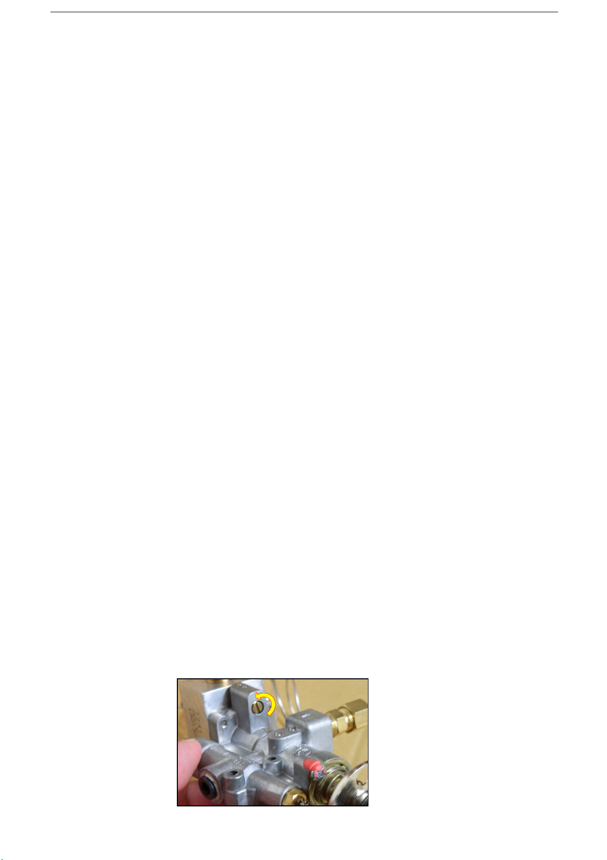
CONVERTING FROM LPG TO NG AND VICE-VERSA
1. Turn-off the pilot.
2. Shut-off the main isolation valve and follow the lock-out/ta -out procedure.
3. Remove the as re ulator.
4. Remove the converter cover from the re ulator. Use a 22mm spanner.
5. Pull-out the converter and position it to your desired as type.
6. Install the converter cover to the re ulator.
7. Re-install the re ulator to the unit. Follow the direction of the arrow on the re ulator when installin .
8. Replace the burner injectors. Follow the burner injector removal procedure. See the parts list for
injector orifice size for specific as type.
9. Replace the ODS injector. Follow the ODS injector removal procedure. See parts list for injector orifice
size for specific as type.
OPENING OF THE RANGE TOP FOR PARTS REPLACEMENT
1. Remove the trivets.
2. Remove the riddle plate assembly (for TR-4F-G12F model)
3. Remove the control knobs.
4. Remove the thermostat control knob. Loosen the lock screw at the knob side.
5. Remove the riddle drip tray. (for TR-4F-G12F model)
6. Remove the mountin screws of the control panel cover. For TR-4F-G12F model, there are two
mountin screws inside the riddle drip tray slot that must be removed to fully remove the control
panel cover.
7. Remove the piezo i niter wire.
8. Remove the control rack mountin screws.
9. Remove the control rack.

18
Trouble shooting
This section provides an easy reference uide to the more common problems that may occur durin the
operation of your equipment. The fault findin uide in this section is intended to help you correct, or at
least accurately dia nose problems with your equipment.
Althou h this section covers the most common problems reported, you may encounter a problem not
covered in this section. In such instances, please contact your local authorized service a ent who will
make every effort to help you identify and resolve the problem. Please note that the service a ent will
require the followin information:
TROUBLESHOOTING RANGE TOP BURNERS
Consult the followin table and the flowchart that be ins on the followin pa e.
Problem Look for-
All burners and pilots in unit will not turn on - Main as supply to unit is “OFF”.
All burners produce excessive carbon deposits - Incorrect as type supplied to unit.
-Incorrect supply pressure
Only some burners in a unit produce excessive -Incorrect orifices.
Carbon deposits - Primary air not adjusted properly.
Only some pilots produce excessive carbon - Pilot as not adjusted properly.
Deposits
Top burner (not oven) will not come on - Safety valve for top burner in “OFF” position. -
- Pilot out
Top section pilot will not stay i nited
-Clo ed orifice
-Draft condition
-Improper ventilation system.
-Air in as line.

19
Troubleshooting
RANGE TOP BURNER
TROUBLESHOOTING
Common checks of all top configurations
Check that the burners are set level in the
support brackets
Check that the burners are clean and all ports
are clear
Remove each burner and check that the
venture is clean and free of buildup and
debris
With each burner removed check that the
orifice size is correct and clean and free of
buildup and debris
Remove the knobs and carefully lower the
top valve cover panel CAUTION! Wiring
attached behind panel on C O base models
Check that each burner valve and orifice is
in alignment with the burner
Shut off the main gas supply
Install a pressure tap in the main gas line
before the range pressure regulator and
install a manometer
Turn on the main gas supply
Re-light all pilots
NOTE: Griddle Tops
NOTE
: Griddles and Hot Tops must be raised
and secured or removed
CAUTION! Before raising or removing
Griddle Tops
Remove the knobs and carefully lower the
control panel CAUTION! Wiring attached
behind panel
Light all burners on the range
NOTE
: Leave
the oven door open
Observe the inlet pressure
Inlet pressures for gases are:
See rating label
If the inlet pressure is low, all equipment on the
main gas line should be lit and the pressure
adjusted
Shut off the range burners and main gas and
remove the pressure tap
Pull the Griddle thermostat bulbs out of the
tubes
Continues on next page
This manual suits for next models
11
Table of contents
Other THOR Oven manuals


