THORLABS PTR302 User manual

PTR302
Rotary Proof Tester
User Guide

PTR302 Rotary Proof Tester
Table of Contents
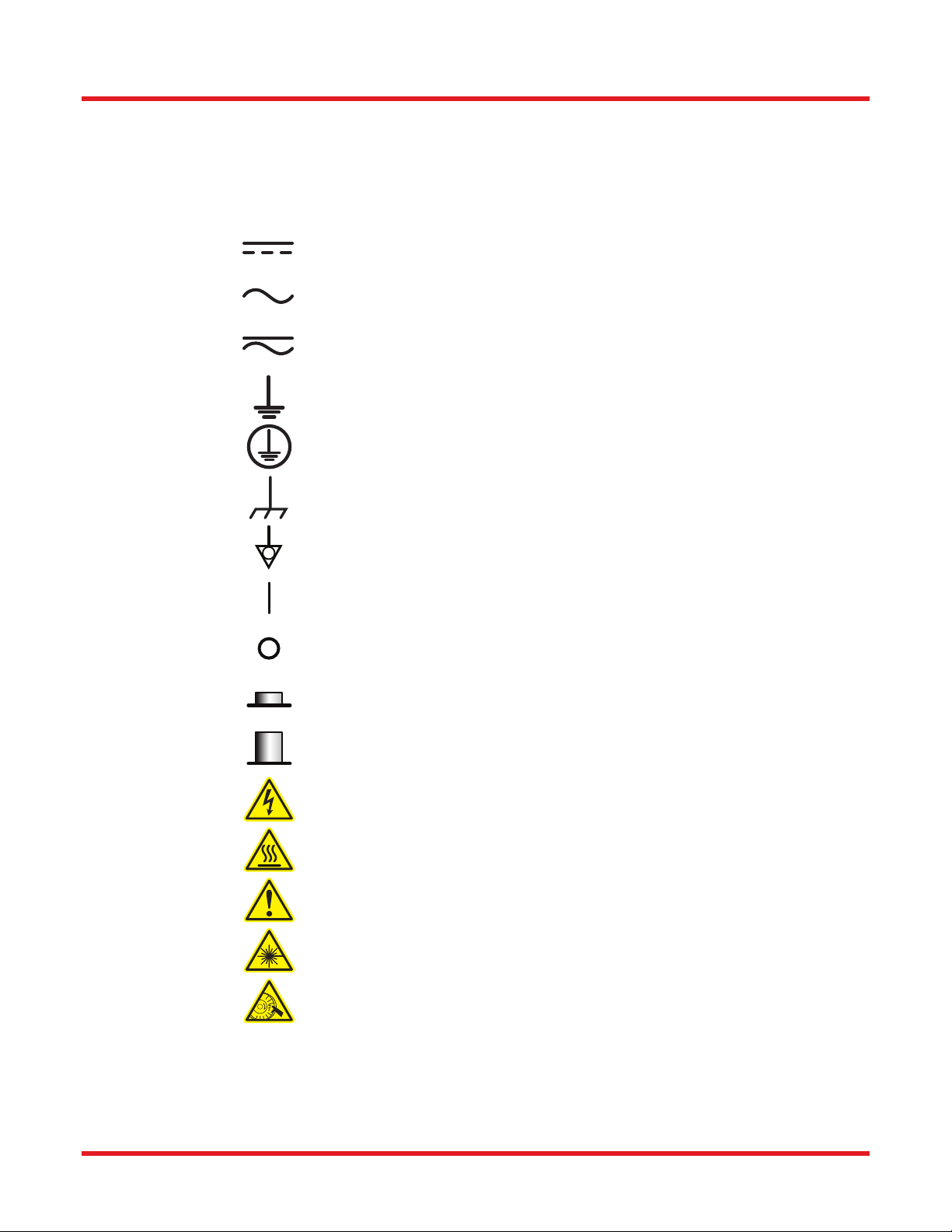
Chapter 1Warning Symbol Definitions..............................................................................................1
Chapter 2Safety....................................................................................................................................2
Chapter 3Description...........................................................................................................................3
3.1.Introduction .....................................................................................................................3
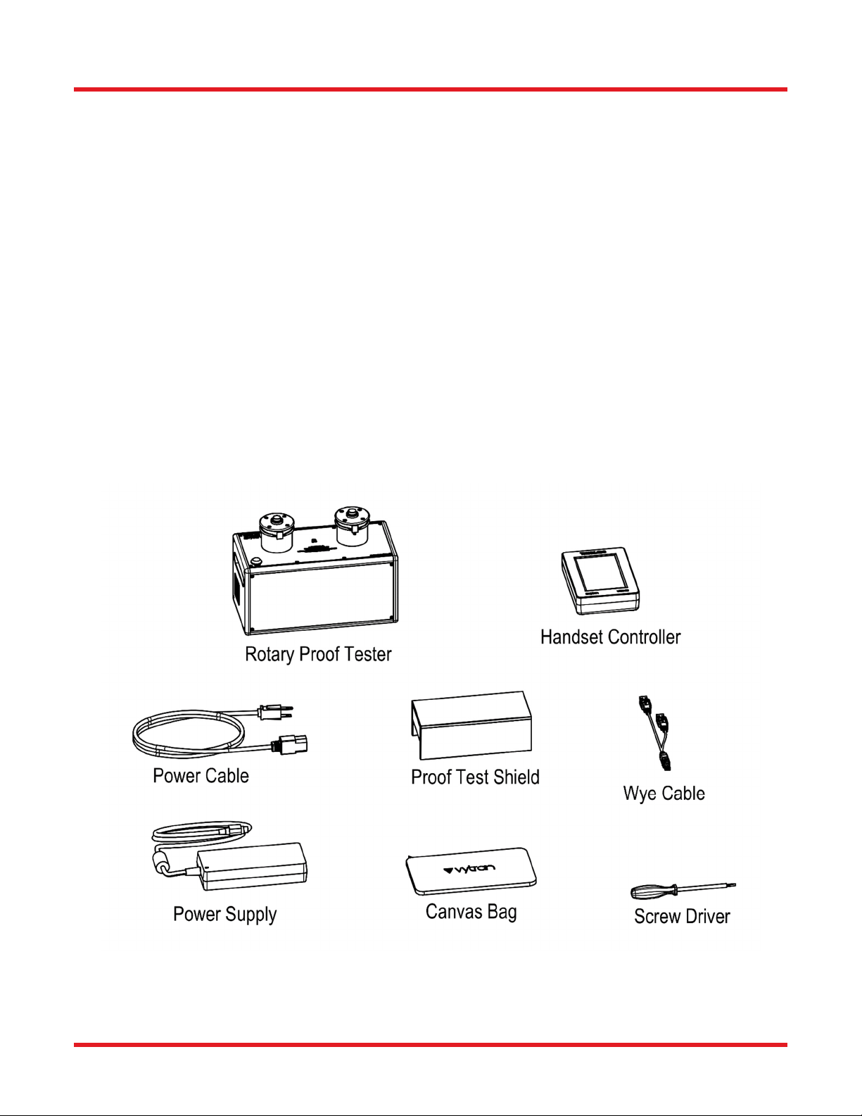
3.2.Parts Checklist ................................................................................................................3
Chapter 4Initialization and Control....................................................................................................4
4.1.Controlling the PTR302...................................................................................................4
4.2.Controlling the PTR302...................................................................................................5
4.2.1.Unit Control Button ................................................................................................................ 5
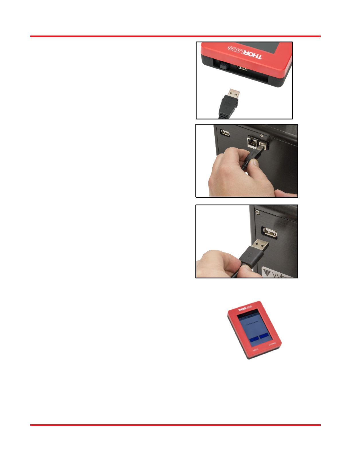
4.3.VYT300C Handset Controller .........................................................................................6
4.3.1.Power Up ............................................................................................................................... 6
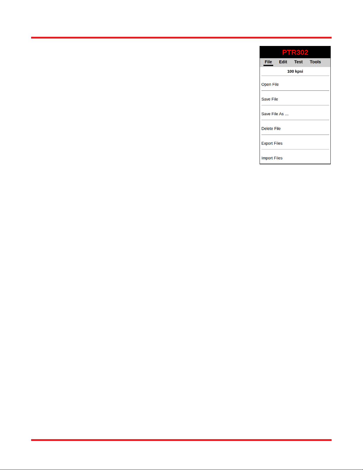
4.3.2.File Menu ............................................................................................................................... 7
4.3.3.Edit Menu .............................................................................................................................. 8
4.3.4.Test ....................................................................................................................................... 8
4.3.5.Tools Menu............................................................................................................................ 9
Chapter 5Proof Test Process.............................................................................................................11
5.1.Position the Fiber for Proof Test .................................................................................11
5.2.Proof Testing .................................................................................................................11
5.3.Adjusting Ramp Rate ....................................................................................................12
Chapter 6Maintenance........................................................................................................................13
6.1.Planned Maintenance....................................................................................................13
6.2.Replace Proof Test Grips .............................................................................................13
6.3.Check Proof Test Calibration / Re-Calibration ...........................................................13
Chapter 7Trouble Shooting................................................................................................................14
7.1.Proof Test Diagnostics .................................................................................................14
Chapter 8Specifications.....................................................................................................................15
Chapter 9Regulatory...........................................................................................................................16
9.1.Waste Treatment is Your Own Responsibility............................................................16
9.2.Ecological Background ................................................................................................16
Chapter 10Thorlabs Worldwide Contacts..........................................................................................17

PTR302 Rotary Proof Tester Chapter 1: Warning Symbol Definitions
Rev D, October 13, 2020 Page 1
Chapter 1 Warning Symbol Definitions
Below is a list of warning symbols you may encounter in this manual or on your device.
Symbol Description
Direct Current
Alternating Current
Both Direct and Alternating Current
Earth Ground Terminal
Protective Conductor Terminal
Frame or Chassis Terminal
Equipotentiality
On (Supply)
Off (Supply)
In Position of a Bi-Stable Push Control
Out Position of a Bi-Stable Push Control
Caution: Risk of Electric Shock
Caution: Hot Surface
Caution: Risk of Danger
Warning: Laser Radiation
Caution: Spinning Blades May Cause Harm

PTR302 Rotary Proof Tester Chapter 2: Safety
Page 2 TTN123488-D02
Chapter 2 Safety
All statements regarding safety of operation and technical data in this instruction manual will only apply when the
unit is operated correctly.
SHOCK WARNING
Unplug the power cord before servicing the unit. Do not operate the unit without all covers and
items properly installed.
CAUTION
Before connecting the AC power cord, make sure the source voltage is between 85 and 265 VAC,
47-63 Hz. Input voltages outside these ranges may result in damage to the unit.
WARNING
Small transparent fiber shards may be present in and around the work area, and as such, the
necessary measures should be taken to ensure the safety of the employee(s).
WARNING
This unit must not be operated in explosive environments. The equipment should be used in a
standard laboratory environment with temperature and humidity control.
Fuses can be replaced by twisting it to release, and then pulling it out of the housing; it is replaced by pushing the
fuse into the housing and then twisting it to lock in place. The fuse is 6.4 A, 250 V.
!
!
!!
!
!

PTR302 Rotary Proof Tester Chapter 3: Description
Rev D, October 13, 2020 Page 3
Chapter 3 Description
3.1. Introduction
The Vytran
®
PTR302 is a proof tester/tension tester. The proof test/tension test station determines the breaking
strength of a fiber or ensures that a fiber or fusion splice meets a minimum strength requirement.
3.2. Parts Checklist
When unpacking the PTR302 for the first time, check to be sure that you have the following:
PTR302 Rotary Proof Tester
Proof Test Shield
Power Supply
AC Power Cord
Handset Controller
Canvas Bag containing:
o Screw Driver
o Wye Cable
If you are missing any of the above or need replacements, please contact Thorlabs
.
Figure 1 System Components

PTR302 Rotary Proof Tester Chapter 4: Initialization and Control
Page 4 TTN123488-D02
Chapter 4 Initialization and Control
4.1. Controlling the PTR302
1. Plug in the AC power cord. The power supply
accepts an AC input of 100 - 240 VAC; 47 -
63 Hz.
2. Connect the AC power cord to the external
power supply.
3. Connect the DC power cable to the unit.
4. Locate the wye cable that is included with the
unit. Locate the USB type A plug that is by itself
on the long leg of the cable.

PTR302 Rotary Proof Tester Chapter 4: Initialization and Control
Rev D, October 13, 2020 Page 5
5. Plug this USB plug into the top USB socket of
the handset. Note that the USB socket on the
side of the handset is dedicated to connecting a
USB flash drive for importing/exporting fiber files
and updating software. Leave it unpopulated for
now.
6. Plug the USB Type B plug of the wye cable into
its socket labeled “Data” on the back of the unit.
7. Plug the USB Type A plug into its socket labeled
“Power Out.”
4.2. Controlling the PTR302
The PTR302 can be operated using either the Blue button on the top of
the unit, or via the Handset Controller, which is used to control the
PTR302 or to reprogram process parameters. The Handset Controller is
the primary controlling option for controlling the device, for service, or for
parameter changes.
4.2.1. Unit Control Button
The PTR302 has a Unit Control Button that enables the user to test the strength of a fusion splice. All parameters
are preset and cannot be changed without the handset controller. The handset controller is also necessary for
readout of the proof test values.
Figure 2 Handset Controller

PTR302 Rotary Proof Tester Chapter 4: Initialization and Control
Page 6 TTN123488-D02
Figure 3 Unit Control Button
Test Button: Activates a Proof Test with the current parameter settings stored within the main unit. The right-
hand mandrel will rotate to apply the set tension to the fiber.
4.3. VYT300C Handset Controller
The PTR302 is operated using the VYT300C handset controller.
4.3.1. Power Up
With the Handset Controller properly connected to the unit, turn on the PTR302 using
the switch located at the back.
The system will go through an initialization process that takes a few seconds. During
initialization, the Handset Controller will auto-detect the PTR302, and if all parameters
read from the unit match the lasted known open file of the Handset, then the handset
will display that file name below the menu tabs. Otherwise, that space is left blank.
The handset will display the Test menu on startup. From here the user can start the
proof test process or navigate to another menu tab. Parameters can be viewed and
changed in the Edit menu. Parameters can be saved to a file, and those files can be
managed in the File menu. The suite of supplemental tools available on the PTR302
can be found on the Tools menu.
Figure 4 Screen
Capture of PTR302 with
file named “100 kpsi”

PTR302 Rotary Proof Tester Chapter 4: Initialization and Control
Rev D, October 13, 2020 Page 7
4.3.2. File Menu
In addition to the standard Open File, Save File, and Save File As options, the
Handset also allows files to be Deleted, Exported, or Imported.
Deleting a file cannot be undone, so the handset will provide a prompt to confirm
deleting a file.
Exporting or importing a file will require a memory device to be connected to the
Program Port of the VYT300C. Selecting Export file will show a list of files which are
currently saved to the handset. A copy of that file will be saved to the connected
memory device in .xml format.
Importing a file will display all folders and all .xml extension files saved to the memory
stick attached. Importing the file will save it to the VYT300C.
Figure 5 PTR302 File
Menu

PTR302 Rotary Proof Tester Chapter 4: Initialization and Control
Page 8 TTN123488-D02
4.3.3. Edit Menu
The parameters that can be edited through the VYT300C Edit Menu are as follows:
Prooftest Level: The load or tension to which the fiber is to be proof tested
in either grams, GPa, kpsi, lb, or N.
Prooftest Units: The unit of measurement, this can be either grams (g),
gigapascals (GPa),
Kilo-pounds per square inch (kpsi), pounds (lb) or
Newtons (N).
Prooftest Timeout: Time limit to abort the proof test process if the Prooftest
Level is not reached
Fiber Diameter: The diameter of the fiber in microns (μm). This diameter is
required to calculate units of tension (kpsi & GPa). Note: Make sure to enter the
diameter of the fiber, not the diameter of the coating.
Figure 6 PTR302 Edit
Menu
4.3.4. Test
Once the Test sequence has started (either by pressing ‘Test’ on the Handset or on
the PTR302) the Test Screen is displayed.
The Test screen displays the current tension reading as well as the status of the test
(started, tension OK, failed to reach tension). The Test Screen remains visible after
the test to allow the user to see the result.
Figure 7 PTR302 Menu

PTR302 Rotary Proof Tester Chapter 4: Initialization and Control
Rev D, October 13, 2020 Page 9
4.3.5. Tools Menu
The tools available on the Handset Controller are listed below.
Prooftest History- Whenever the PTR302 carries out a proof test, the Handset Controller records the target
tension and, if unsuccessful, the tension at which the fiber broke.
Terminal- This allows serial communication with the PTR302. Enter the command in the box above the
Send and Close buttons or select a command previously entered. Then press the Send button.
Responses to the command will be displayed in the box in the top portion of the window.
Version- This displays Firmware, Macro File, Setup File, and Application
versions. There is also an option to apply updates via the Program Port.
Export Log File- This saves a copy of the current Log File to a memory device
connected to the Program Port
User- This replaces the Password and Access Permissions from the Settings
Menu of the Handset Controller. The options available are:
Full Access - allows full read-write access of parameters and files,
the ability to change User Access Permissions.
Read Only - allows user to Open Files but does not allow the user to
make or save any changes to the file parameters.
No Read or Write - does not allow the user to make or save and
changes to the file parameters, and does not allow the user to open
a new file
Figure 9 PTR302 Tools
Menu
The current level of access is displayed at the top of the User dialog window. Initially there is no
password configured and all users have Full Access. To configure a password, select the Enter
password button and then press Ok. Then select Change Password and enter the desired password.
You can then set the desired level of access. Once the password is configured and the level of
access is selected, press Log Out. The handset is now protected at the Access Level selected.
To make any changes to this in the future, you must enter the Password you configured. You now
have Full Access. Full Access will remain in effect until you select Log Out. To remove Password
Protection, select the Change Password option and enter an empty string for the required password.

PTR302 Rotary Proof Tester Chapter 4: Initialization and Control
Page 10 TTN123488-D02
Figure 10 PTR302 Windows for Prooftest History and Terminal
Figure 11 PTR302 Tools Windows for Version, Export Log File, and User

PTR302 Rotary Proof Tester Chapter 5: Proof Test Process
Rev D, October 13, 2020 Page 11
Chapter 5 Proof Test Process
The proof test station of the PTR302 can be used to determine the breaking strength of an optical fiber or to ensure
that a fiber or fusion splice meets a minimum strength requirement
.
To proof or tension test a fiber, the section of fiber to be tested is located between two mandrels. The ends of the
fibers are wrapped once around each mandrel and held in place by an integral clamping mechanism. A load is
automatically applied to the fiber by the rotation of the right-hand mandrel. The load can be taken up to a
predetermined level and released (proof test) or it can be taken up to the breaking strength of the fiber (tension
test). The peak tension is recorded and can be displayed in units of load or tension.
5.1. Position the Fiber for Proof Test
Press and hold down the buttons on top of the mandrels to open the mandrel clamps. Position the fiber under the
clamps such that the splice region or section of fiber to be tested is centered between the mandrels. Release the
buttons to hold the fiber in position. Re-check that the splice is centered between the mandrels. Wrap the fiber once
around each mandrel, ideally near the center of the rubber grip. Make sure not to overlap the fiber under the clamp
as this could cause local stresses that may weaken or break the fiber during the proof test. When properly loaded
the fiber should be taut with minimal slack between the mandrels. Note: The proof test reading will not be affected
by any residual tension left in the fiber after loading.
Figure 12 Load Fiber for Proof Testing
5.2. Proof Testing
Configure the PTR302 to proof test to the desired level as described in Section 4.3.3.
WARNING
Always use the safety shield or wear safety glasses when proof or tension testing fiber. The fiber
under test can shatter and send glass particles flying.
The procedures for the automatic proof test are as follows:
1. Set the Proof Test parameters.
2. Load the fiber to be tested.
3. Make sure the safety shield is in place and that you are wearing safety glasses.
!
!

PTR302 Rotary Proof Tester Chapter 5: Proof Test Process
Page 12 TTN123488-D02
Note: Anyone observing the test should also take precautions against flying glass particles.
4. Press the Test button to initiate the proof test cycle.
The maximum tension applied to the fiber will be recorded and displayed. If the fiber breaks prior to reaching the
Automatic Proof Test level, the breaking strength will be displayed.
5.3. Adjusting Ramp Rate
The Ramp Rate is the rate at which tension to the fiber is applied during a Proof Test / Tension Test. This rate can
be adjusted through the Ramp Screw as shown in Figure 13. To decrease the Ramp Rate turn the Ramp Screw
clockwise; to increase the Ramp Rate turn it counterclockwise.
WARNING
Always use the safety shield or wear safety glasses when proof or tension testing fiber. The fiber
under test can shatter and send glass particles flying.
Figure 13 Adjust the Ramp Rate
The procedures for adjusting the Ramp Rate are as follows:
1. Set the desired proof test level (see Section 4.3.3).
2. Make sure the proof test timeout is set for 10 seconds or greater.
3. Load a piece of test fiber onto the proof test mandrels (see Section 5.1).
4. Make sure the safety shield is in place or wear safety glasses.
5. Initiate the Proof Test by pressing the Test button.
6. Note the time it takes for the desired proof test Peak Tension level will be reached starting from when the
right-hand mandrel just starts to rotate. The Peak Tension should be reached in approximately 5 seconds.
Adjust as necessary.
!
!

PTR302 Rotary Proof Tester Chapter 6: Maintenance
Rev D, October 13, 2020 Page 13
Chapter 6 Maintenance
The purpose of the maintenance section is to define the planned maintenance requirements of the PTR302. Where
appropriate maintenance procedures are included.
6.1. Planned Maintenance
The PTR302 proof tester is designed for a production environment to give trouble free operation provided normal
planned maintenance is adhered to. Maintenance and repair procedures should only be performed by trained
personnel. Improper service and/or repair could result in the safety features being disabled and can also lead to
damage that will not be covered under warranty.
Planned Maintenance Schedule
Maintenance Every
Cycle
Every
Shift Daily Monthly 3
Months
12
Months
Replace Proof Test Grips
Check Proof Test Calibration /
Recalibrate
6.2. Replace Proof Test Grips
Remove the 4 flat head screws on top of the proof test
mandrel and lift off the flanged top. Depress the
mandrel clamp button and remove the rubber grip.
Install a new grip making sure that the grip is uniformly
positioned around the mandrel and seated below the
bottom flange. Replace the top flange and 4 flat head
screws. Make sure that the mandrel clamp operates
freely and that the rubber grip does not rub against the
clamping arm. After replacing the proof test grips, a
calibration check should be performed.
6.3. Check Proof Test Calibration / Re-
Calibration
It is recommended that the PTR302 be returned to
Thorlabs annually for calibration check and/or
recalibration. A calibration fixture is available for
customers who prefer to perform this function in-house.
Figure 14 Replace Proof Test Grip

PTR302 Rotary Proof Tester Chapter 7: Trouble Shooting
Page 14 TTN123488-D02
Chapter 7 Trouble Shooting
7.1. Proof Test Diagnostics
Problem Possible Cause Solution
Fiber slips at very high tension
levels.
Proof test grips are dirty. Clean proof test grips with a cotton
swab dipped in alcohol.
Proof test grips are worn out.
Call Thorlabs for replacement proof
test grips and replace as described
in Section 6.2: Replace Proof Test
Grips.
Tension levels appear unusually
high or low for the particular
fiber being tested.
Wrong fiber diameter entered.
The fiber diameter is used in the
tension level calculation. Check the
setting for the current fiber
diameter.
(
See Section 4.3.
)

PTR302 Rotary Proof Tester Chapter 8: Specifications
Rev D, October 13, 2020 Page 15
Chapter 8 Specifications
Specifications
Proof Tester T
y
pe Rotar
y
Load Mechanism Ø2"
(
50.8 mm
)
Rotatin
g
Mandrel1
Fiber Spacin
g
5"
(
127 mm
)
Minimum Fiber Len
g
th 17"
(
432 mm
)
Maximum Load 89 N (20 lbs)
>800 kpsi
(
5.5 GPa
)
for a Ø125 µm Fiber
Accurac
y
±2%
Ramp Rate2 Manual, ≤22.2 N/s
(
5 lbs/s
)
Displa
y
Units lbs, k
g
, N, kpsi, and GPa
Dimensions
(
L x W x H
)
10.14" × 5.85" × 7.27"
(
257.4 mm × 148.5 mm × 184.5 mm
)
1Check the minimum short-term bend radius of the fiber to be tested to ensure its compatibility with the Ø2" mandrel.
2The ramp rate is the rate at which the load is applied to the fiber.

PTR302 Rotary Proof Tester Chapter 9: Regulatory
Page 16 TTN123488-D02
Chapter 9 Regulatory
As required by the WEEE (Waste Electrical and Electronic Equipment Directive) of the European Community and
the corresponding national laws, Thorlabs offers all end users in the EC the possibility to return “end of life” units
without incurring disposal charges.
This offer is valid for Thorlabs electrical and electronic equipment:
Sold after August 13, 2005
Marked correspondingly with the crossed out “wheelie bin” logo (see right)
Sold to a company or institute within the EC
Currently owned by a company or institute within the EC
Still complete, not disassembled and not contaminated
As the WEEE directive applies to self-contained operational electrical and electronic products, this end of life take
back service does not refer to other Thorlabs products, such as:
Pure OEM products, that means assemblies to be built into a unit by the user (e. g. OEM laser driver cards)
Components
Mechanics and optics
Left over parts of units disassembled by the user (PCB’s, housings etc.).
If you wish to return a Thorlabs unit for waste recovery, please contact Thorlabs or your nearest dealer for further
information.
9.1. Waste Treatment is Your Own Responsibility
If you do not return an “end of life” unit to Thorlabs, you must hand it to a company specialized in waste recovery.
Do not dispose of the unit in a litter bin or at a public waste disposal site.
9.2. Ecological Background
It is well known that WEEE pollutes the environment by releasing toxic products during decomposition. The aim of
the European RoHS directive is to reduce the content of toxic substances in electronic products in the future.
The intent of the WEEE directive is to enforce the recycling of WEEE. A controlled recycling of end of life products
will thereby avoid negative impacts on the environment.
Wheelie Bin Logo

PTR302 Rotary Proof Tester Chapter 10: Thorlabs Worldwide Contacts
Rev D, October 13, 2020 Page 17
Chapter 10 Thorlabs Worldwide Contacts
For technical support or sales inquiries, please visit us at www.thorlabs.com/contact for our most up-to-date
contact information.
USA, Canada, and South America
Thorlabs, Inc.
UK and Ireland
Thorlabs Ltd.
sales.uk@thorlabs.com
techsupport.uk@thorlabs.com
Europe
Thorlabs GmbH
europe@thorlabs.com
Scandinavia
Thorlabs Sweden AB
France
Thorlabs SAS
Brazil
Thorlabs Vendas de Fotônicos Ltda.
Japan
Thorlabs Japan, Inc.
China
Thorlabs China
chinasales@thorlabs.com

www.thorlabs.com
Table of contents
Other THORLABS Test Equipment manuals