Thorne & Derrick KATflow 100 User manual
Operating Instructions
KA
Tflow 100
Ultrasonic Flow Transmitter

Katronic Technologies Ltd.
Earls Court
13 Warwick Street
Earlsdon, Coventry
West Midlands CV5 6ET
United Kin dom
Tel. +44 (0)2476 714111
Fax +44 (0)2476 715446
Internet www.katronic.co.uk
E-mail mail@katronic.co.uk
Operating Instructions KATflow 100
Version V11EN160420
Copyri ht © 2016
All ri hts reserved.

KATflow 100 Table of ontents
KATflow 100
Operatin Instructions
Table of ontents
Page
1 Safety instructions, legal requirements, warranty, return policy.................5
1.1 Symbols used in these operatin instructions..............................................5
1.2 Safety instructions.......................................................................................5
1.3 Warranty...................................................................................................... 6
1.4 Return policy................................................................................................ 6
1.5 Le islative requirements..............................................................................6
2 Introduction...................................................................................................... 7
3 Installation........................................................................................................8
3.1 Unpackin and stora e................................................................................8
3.1.1 Unpacking.............................................................................................8
3.1.2 Storage ................................................................................................8
3.1.3 Identification of components.................................................................8
3.2 Clamp-on sensor installation.......................................................................9
3.3 Installation location......................................................................................9
3.4 Pipe preparation..........................................................................................12
3.5 Clamp-on sensor mountin confi urations and separation distance............12
3.6 Flowmeter installation..................................................................................13
3.6.1 all mounting.......................................................................................13
3.6.2 Electrical connections...........................................................................15
3.7 Clamp-on sensor mountin .........................................................................16
3.7.1 Sensor pipe mounting configurations....................................................16
3.7.2 Acoustic coupling gel............................................................................16
3.7.3 Correct positioning of the sensors........................................................17
3.7.4 Sensor mounting with tension straps....................................................17
4 Operation.......................................................................................................... 19
4.1 Switchin On/Off.......................................................................................... 19
4.2 Keypad and display.....................................................................................19
4.2.1 Keypad key functions............................................................................19
4.2.2 Display functions..................................................................................21
4.3 Quick setup wizard......................................................................................22
4.4 Measurements.............................................................................................25
4.4.1 Main process value (PV) display...........................................................26
4.4.2 Diagnostic displays...............................................................................26
4.4.3 Totalisers..............................................................................................27
4.4.4 Datalogger............................................................................................27
5 ommissioning................................................................................................ 28
5.1 Menu structure............................................................................................28
5.2 Dia nostics.................................................................................................. 33
5.3 Display settin s...........................................................................................33
5.4 Output confi uration....................................................................................34
5.4.1 Serial interface RS 232.........................................................................34
5.4.2 Serial interface RS 485.........................................................................34
3

KATflow 100 Table of ontents
5.4.3 HART compatible output.......................................................................34
5.4.4 Analogue current output ......................................................................35
5.4.4 Analogue voltage output ......................................................................35
5.4.4 Analogue frequency output...................................................................35
5.4.5 Digital Open-Collector output................................................................36
5.4.6 Digital relay output................................................................................36
5.5 Input confi uration.......................................................................................36
5.5.1 PT100 inputs........................................................................................36
5.5.2 Analogue current input 0/4 ... 20 mA.....................................................37
5.6 Heat quantity measurement (HQM).............................................................37
5.7 Sound velocity measurement (SVM)...........................................................37
5.8 Scope function.............................................................................................38
6 Maintenance..................................................................................................... 39
7 Troubleshooting...............................................................................................40
8 Technical data.................................................................................................. 42
9 Specification..................................................................................................... 48
10 Index................................................................................................................ 50
Appendix A.......................................................................................................... 51
Appendix B......................................................................................................... 52
4
KATflow 100 1 Safety instructions, legal requirements,warranty, return policy
1 Safety instructions, legal requirements,warranty,
return policy
1.1 Symbols used in these operating instructions
Danger
This symbol represents an immediate hazardous situation which could result in
serious injury, death or damage to the equipment. Where this symbol is shown,
do not use the equipment further unless you have fully understood the nature of the
hazard and have taken the required precautions.
Attention
This symbol indicates important instructions which should be respected in order to
avoid dama in or destroyin the equipment. Follow the the precautions iven in
these instructions to avoid the hazard. Call our service team if necessary.
all service
Where this symbol is shown call our service team for advice if necessary.
Note
This symbol indicates a note or detailed set-up tip.
Information point.
Operator keys are printed in bold typeface and placed in pointed brackets.
1.2 Safety instructions
●Do not install, operate or maintain this flowmeter without readin , under-
standin and followin these operatin instructions, otherwise injury or
dama e may result.
●Study these operatin instructions carefully before the installation of the
equipment and keep them for future reference.
●Observe all warnin s, notes and instructions as marked on the packa in ,
on the equipment, and detailed in the operatin instructions.
●Do not use the instrument under wet conditions with the battery cover re-
moved or opened.
●Follow the unpackin , stora e and preservation instructions to avoid dam-
a e to the equipment.
●Install the equipment and cablin securely and safely accordin to the rel-
evant re ulations.
●If the product does not operate normally, please refer to the service and
troubleshootin instructions, or contact KATRONIC for help.
5
!
<BRK>
!
•
KATflow 100 1 Safety instructions, legal requirements,warranty, return policy
1.3 Warranty
●Any product purchased from KATRONIC is warranted in accordance with
the relevant product documentation and as specified in the sales contract
provided it has been used for the purpose for which it has been desi ned
and operated as outlined in these operatin instructions. Misuse of the
equipment will immediately revoke any warranty iven or implied.
●Responsibility for suitability and intended use of this ultrasonic flowmeter
rests solely with the user. Improper installation and operation of the flow-
meter may lead to a loss of warranty.
●Please note that there are no operator-serviceable parts inside the equip-
ment. Any unauthorised interference with the product will invalidate the
warranty.
1.4 Return policy
If the flowmeter has been dia nosed to have a problem, it can be returned to KAT-
RONIC for repair usin the Customer Returns Note (CRN) attached to the Ap-
pendix of this manual. KATRONIC re ret that for safety reasons we cannot accept
the return of the equipment unless accompanied by the completed CRN.
1.5 Legislative requirements
The flowmeter is desi ned to meet the safety requirements in accordance with
sound en ineerin practice. It has been tested and has left the factory in a condi-
tion in which it is safe to operate. The equipment is in conformity with the statutory
requirements of the EC directive and complies with applicable re ulations and
standards for electrical safety EN 61010 and electroma netic compatibility EN
61326. A CE Declaration of Conformity has been issued in that respect, a copy of
which can be found in the Appendix of these operatin instructions.
The Waste Electrical and Electronic Equipment Directive (WEEE Directive) aims to
minimise the impact of electrical and electronic oods on the environment by in-
creasin re-use and recyclin and by reducin the amount of WEEE oin to land-
fill. It seeks to achieve this by makin producers responsible for financin the col-
lection, treatment, and recovery of waste electrical equipment, and by obli in dis-
tributors to allow consumers to return their waste equipment free of char e.
KATRONIC offers its customers the possibility of returnin unused and obsolete
equipment for correct disposal and recyclin . The Dustbin Symbol indicates that
when the last user wishes to discard this product, it must be sent to appropriate fa-
cilities for recovery and recyclin . By not discardin this product alon with other
household-type waste, the volume of waste sent to incinerators or landfills will be
reduced and natural resources will be conserved. Please use the Customer Return
Note (CRN) in the Appendix for return to KATRONIC.
All products manufactured by KATRONIC are compliant with the relevant aspects
of the RoHS Directive.
6
RoHS Directive
CE marking
WEEE Directive

KATflow 100 2 Introduction
2 Introduction
The KATflow 100 is an ultrasonic flow transmitter employin clamp-on sensors for
the measurement of liquids in full, enclosed pipes. Flow measurements can be un-
dertaken without interruption of the process or interference with the inte rity of the
pipeline. The clamp-on sensors are attached to the outside of the pipes. The KAT-
flow 100 uses ultrasonic si nals for measurement of the flow, employin the transit-
time method.
Ultrasonic si nals are emitted by a transducer installed on a pipe and received by a
second transducer. These si nals are emitted alternately in the direction of flow and
a ainst it. Because the medium is flowin , the transit time of the sound si nals
propa atin in the direction of flow is shorter than the transit time of the si nal
propa atin a ainst the direction of flow. The transit-time difference ΔT is meas-
ured and allows the determination of the avera e flow velocity alon the path of
acoustic propa ation. A profile correction is then performed to obtain the avera e
flow velocity over the cross-sectional area of the pipe, which is proportional to the
volumetric flow rate.
7
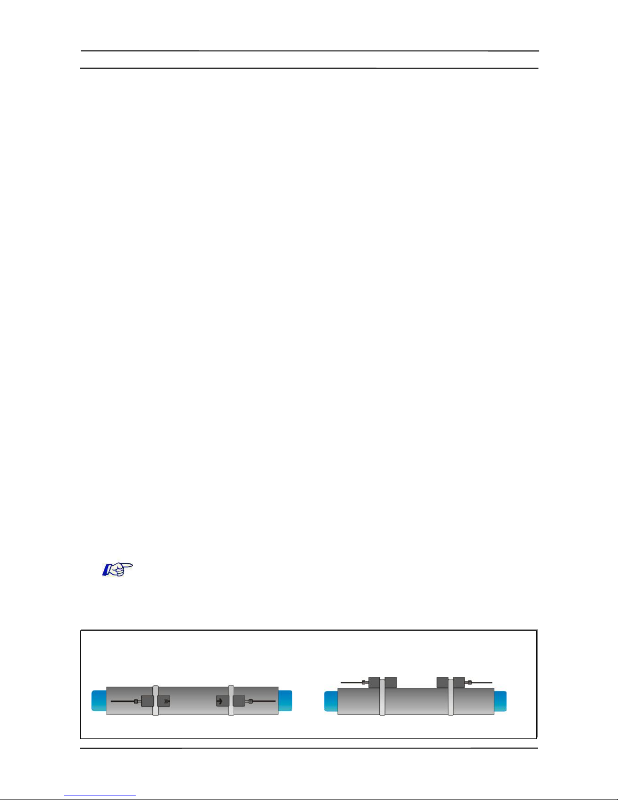
Illustration 1: Clamp-on ultrasonic sensor configuration
Measuring principle
Illustration 2: Transit-time measuring principle
Clamp on trans
it time flow transmit
ter

KATflow 100 3 Installation
3 Installation
3.1 Unpacking and storage
3.1.1 Unpacking
Care should be taken when openin the box containin the flowmeter, any mark-
in s or warnin s shown on the packa in should be observed prior to openin . The
followin steps should then be taken:
●Unpack the flowmeter in a dry area.
●The flowmeter should be handled with care and not left in an area where it
could be subject to physical shocks.
●If usin a knife to remove packa in care should be taken not to dama e
the flowmeter or cables.
●The flowmeter packa e and contents should be checked a ainst the deliv-
ery note supplied and any missin items reported immediately.
●The flowmeter packa e and contents should be checked for si ns of dam-
a e durin transport and any problems reported immediately.
●The vendor accepts no responsibility for dama e or injury caused durin
the unpackin of the instrumentation supplied.
●Excess packin materials should be either recycled or disposed of in a suit-
able way.
3.1.2 Storage
If stora e is necessary, the flowmeter and sensors should be stored:
●in a secure location,
●away from water and harsh environmental conditions,
●in such a way as to avoid dama e,
●small items should be kept to ether in the ba s provided to avoid loss.
3.1.3 Identification of components
The followin items are typically supplied (please refer to your delivery note for a
detailed description):
●KATflow 100 ultrasonic flow transmitter
●Clamp-on sensors (one pair for sin le channel operation, two pairs for dual
channel operation)
●Sensor connection cable(s) if not direct sensor connection
●Sensor mountin accessories
●Couplin component
●Operatin instructions
●Project and/or hazardous area documentation (optional)
●Calibration certificate(s) (optional)
8
KATflow 100 3 Installation
3.2 lamp-on sensor installation
The correct selection of the sensor location is crucial for achievin reliable meas-
urements and hi h accuracy. Measurement must take place on a pipe in which
sound can propa ate (see Acoustic propa ation) and in which a rotationally sym-
metrical flow profile is fully developed (see Strai ht pipe len ths).
The correct positionin of the transducers is an essential condition for error-free
measurements. It ensures that the sound si nal will be received under optimal con-
ditions and evaluated correctly. Because of the variety of applications and the differ-
ent factors influencin the measurement, there can be no standard solution for the
positionin of the transducers.
The correct position of the transducers will be influenced by the followin factors:
●diameter, material, linin , wall thickness and eneral condition of the pipe,
●the medium flowin in the pipe,
●the presence of as bubbles and solid particles in the medium.
Check that the temperature at the selected location is within the operatin temper-
ature ran e of the transducers (see Specification).
After the sensor location has been selected, make sure that that supplied cable is
lon enou h to reach the flow transmitter mountin location. Ensure that the tem-
perature at the selected location is within the ambient operatin temperature ran e
of the flow transmitter (see Specification).
Acoustic propa ation is achieved when the flowmeter is able to receive sufficient
si nal from the transmitted ultrasonic pulses. The si nals are attenuated in the
pipe material, the medium and at each of the interfaces and reflections. External
and internal pipe corrosion, solid particles and as content in the medium contribute
heavily to si nal attenuation.
Sufficient strai ht len ths of pipe on the inlet and outlet of the measurin location
ensure an axi-symmetrical flow profile in the pipe, which is required for ood meas-
urement accuracy. If insufficient strai ht len ths of pipe are available for your ap-
plication measurements are still obtainable, but the certainty of the measurement
can be reduced.
3.3 Installation location
Select an installation location followin the recommendations in Table 1 and try to
avoid measurin
●in the vicinity of deformations and defects of the pipe,
●near weldin seams,
●where deposits could be buildin up in the pipe.
For a horizontal pipe:
Select a location where the transducers can be mounted on the side of the pipe, so that the sound waves emitted by
the transducers propa ate horizontally in the pipe. In this way, the solid particles deposited on the bottom of the pipe
and the as pockets developin at the top will not influence the propa ation of the si nal.
Correct Incorrect
9
Acoustic propagation
Straight pipe lengths

KATflow 100 3 Installation
For a free inlet or outlet pipe section:
Select the measurin point at a location where the pipe cannot run empty.
Correct Disadvantageous
Correct Disadvantageous
For a vertical pipe:
Select the measurin point at a location where the liquid flows upward to ensure that the pipe is completely filled.
Correct Incorrect
Look for a sensor installation location with sufficient strai ht pipe to obtain accurate
measurements. Please refer to Table 2 as a uideline for recommended distances
from disturbance sources.
Disturbance source: 90°-elbow
Inlet Outlet
L ≥ 10 D L ≥ 5 D
Disturbance source: 2 x 90°-elbows in one plane
Inlet Outlet
L ≥ 25 D L ≥ 5 D
10
Table 1: Recommendations for sensor mounting location

KATflow 100 3 Installation
Disturbance source: 2 x 90°-elbows in different planes
Inlet Outlet
L ≥ 40 D L ≥ 5 D
Disturbance source: T-section
Inlet Outlet
L ≥ 50 D L ≥ 10 D
Disturbance source: diffuser
Inlet Outlet
L ≥ 30 D L ≥ 5 D
Disturbance source: reducer
Inlet Outlet
L ≥ 10 D L ≥ 5 D
Disturbance source: valve
Inlet Outlet
L ≥ 40 D L ≥ 10 D
Disturbance source: pump
Inlet
L ≥ 50 D
Table 2: Recommended distances from disturbance sources
11
KATflow 100 3 Installation
3.4 Pipe preparation
●Clean dirt and dust from around the area of the pipework where the
sensors are to be placed.
●Remove loose paint and rust with a wire brush or file.
Firmly bonded paint does not necessarily need to be removed provided the flow-
meter dia nostics indicate sufficient si nal stren th.
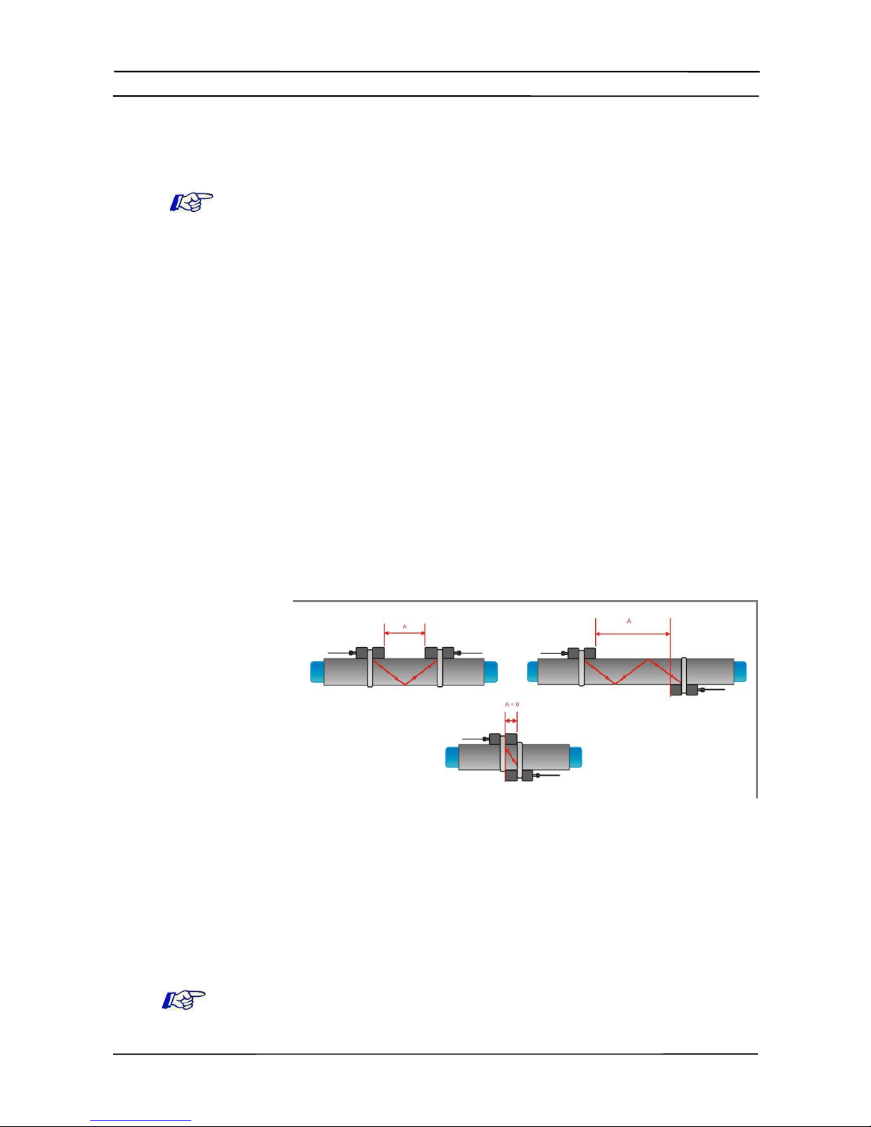
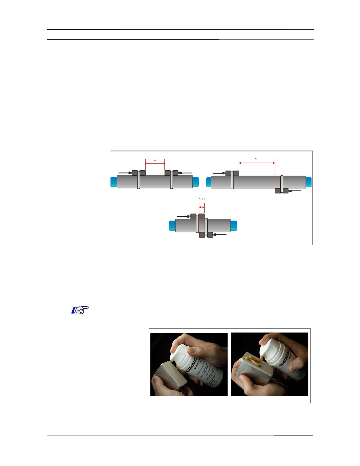
3.5 lamp-on sensor mounting configurations and separation
distance
The most common clamp-on sensor mountin confi uration is the Reflection Mode,
sometimes known as V-Mode (see Illustration 3, sketch (1). Here, the ultrasonic
si nal passes twice throu h the medium (2 si nal passes). The Reflection Mode is
the most convenient mountin method as the transducer separation distance can
be measured easily and the sensors can be accurately ali ned. This method
should be used whenever possible.
An alternative mountin confi uration (Illustration 3, sketch (3)) is the Dia onal
mode (Z-Mode). The si nals travel only once throu h the pipe. This method is of-
ten used for lar er pipes where reater si nal attenuation mi ht occur.
Further variation of the Reflection and the Dia onal Modes are possible by alterin
the number of passes throu h the pipe. Any even number of passes will require
mountin the sensors on the same side of the pipe, while with an odd number of
passes, the sensors must be mounted on opposite sides of the pipe. Commonly,
for very small pipes, sensor mountin confi urations such as 4 passes (W-mode)
or 3 passes (N-mode) are used (Illustration 3, sketch (2)).
The transducer separation distance A is measured from the inside ed es of the
sensor heads as shown in illustration 3. It is automatically calculated by the flow-
meter based on the parameter entries for pipe outside diameter, wall thickness, lin-
in material and thickness, medium, process temperature, the sensor type and the
selected number of si nal passes.
A ne ative separation distance A < 0 can occur for mountin confi urations on
small pipes where dia onal mode operation has been selected (see Illustration 3,
sketch (3). Ne ative separation distances may be su ested for reflection mode in-
stallations, but are not possible. In these cases, use dia onal mode or a lar er
number of passes.
12
Illustration 3: Clamp-on sensor mounting configurations and sensor spacing
Sensor spacing
Diagonal Mode
Reflection Mode
Transducer separa
tion distance
KATflow 100 3 Installation
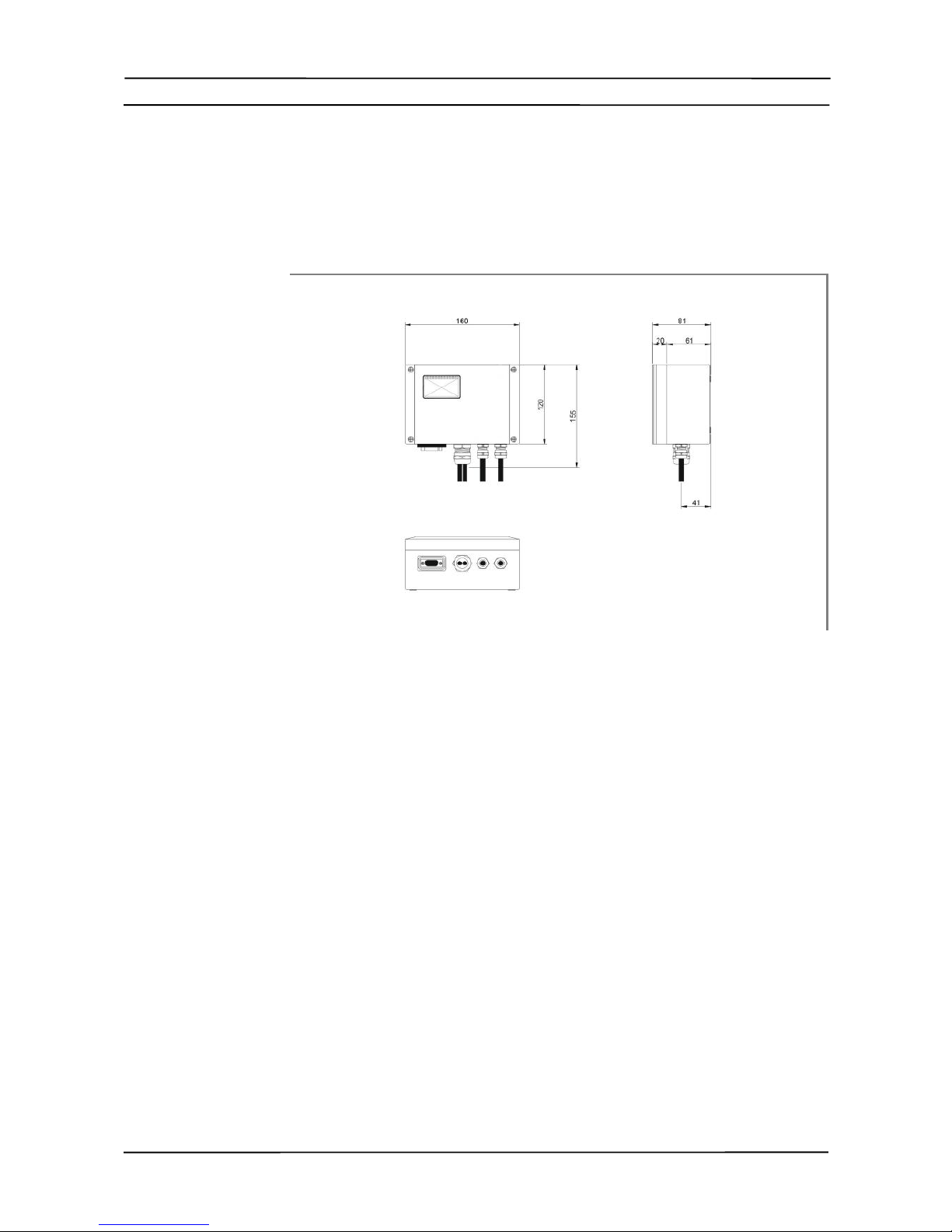
3.6 Flowmeter installation
3.6.1 Wall mounting
The KATflow 100 is a wall mounted device and can be installed usin suitable
screws and wall plu s accordin to the followin drawin s.
13
Drawing 1: Outline dimensions KATflow 100 ultrasonic flowmeter
Flowmeter outline di
mensions
KATflow 100 3 Installation
Make sure that the ambient temperature is within the -10 ... 60 °C operatin tem-
perature ran e specified for the flowmeter unit.
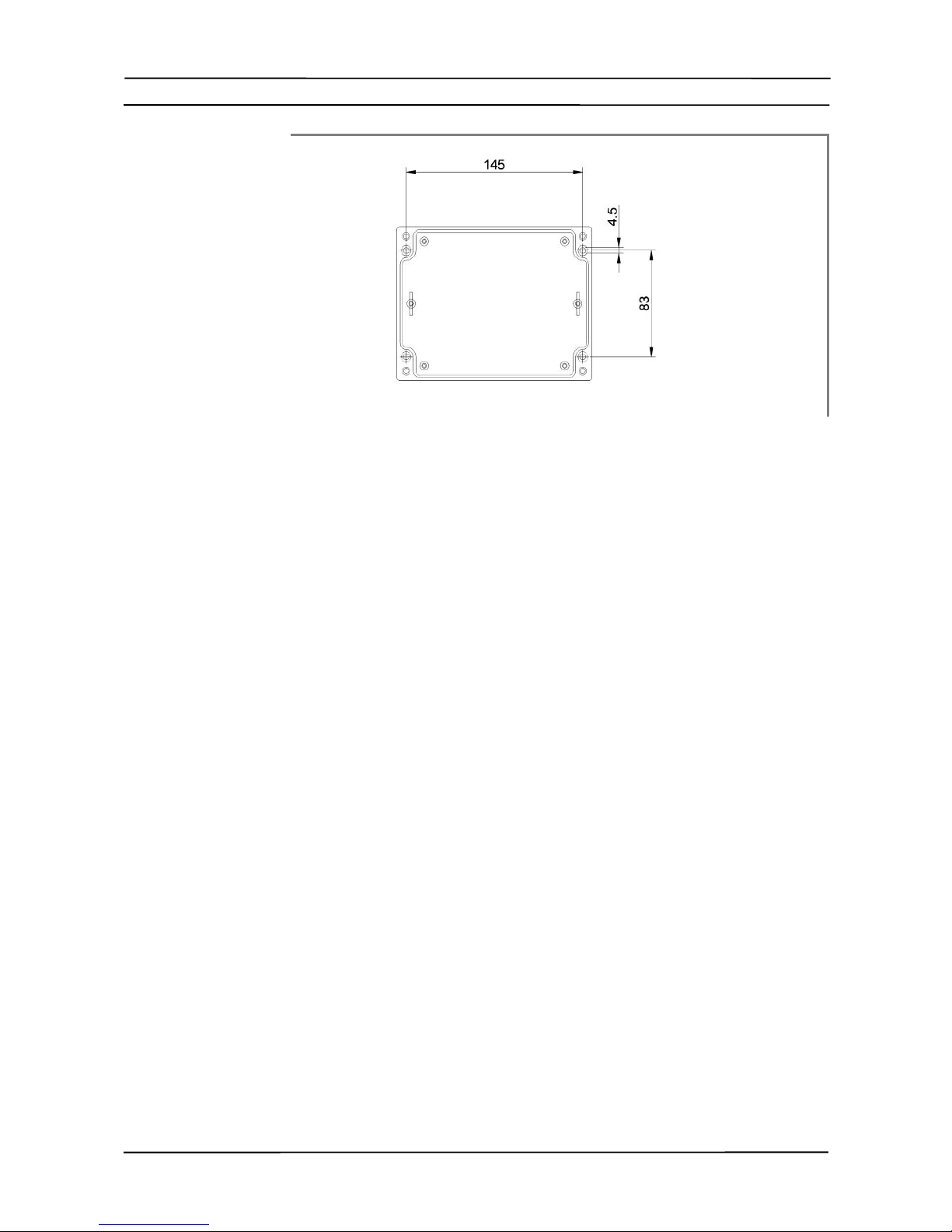
14
Drilling aid for wall
mounting
Drawing 2: Drilling aid for wall mounting
!
KATflow 100 3 Installation
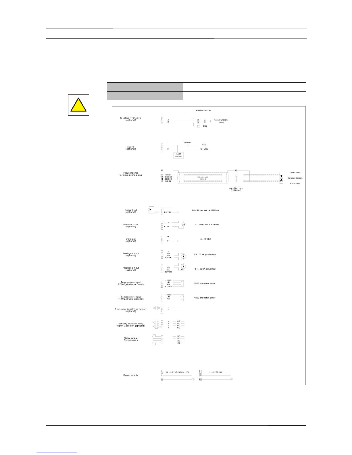
3.6.2 Electrical connections
Please note that in order to supply the unit with MAINS POWER, the equipment
must be protected by suitably sized switches and circuit breakers.
100 ... 240 V A , 50/60 Hz 10 W
9 ... 36 V D 10 W
15
Drawing 3: Electrical connection diagram for the KATflow 100 flow transmitter
!
Electrical wiring
!
KATflow 100 3 Installation
3.7 lamp-on sensor mounting
Before the sensors can be mounted
●the installation location should have been determined,
●a sensor mountin method should be chosen,
●the flowmeter must be mechanically and electrically installed,
●the sensors must be connected to the flowmeter.
Dependin on which sensor mountin method is bein used, the clamp on sensors
are either mounted on the same side of the pipe (Reflection Mode) or on opposite
sides of the pipe (Dia onal Mode). The sensor spacin is calculated by the flow-
meter from the pipe parameters entered.
3.7.1 Sensor pipe mounting configurations
3.7.2 Acoustic coupling gel
In order to obtain acoustical contact between the pipe and the sensors, apply a
bead of acoustic couplin el len thwise down the centre of the contact area of the
sensors.
16
Illustration 4: Sensor pipe mounting configurations
Illustration 5: Application of acoustic coupling gel
Sensor mounting

KATflow 100 3 Installation
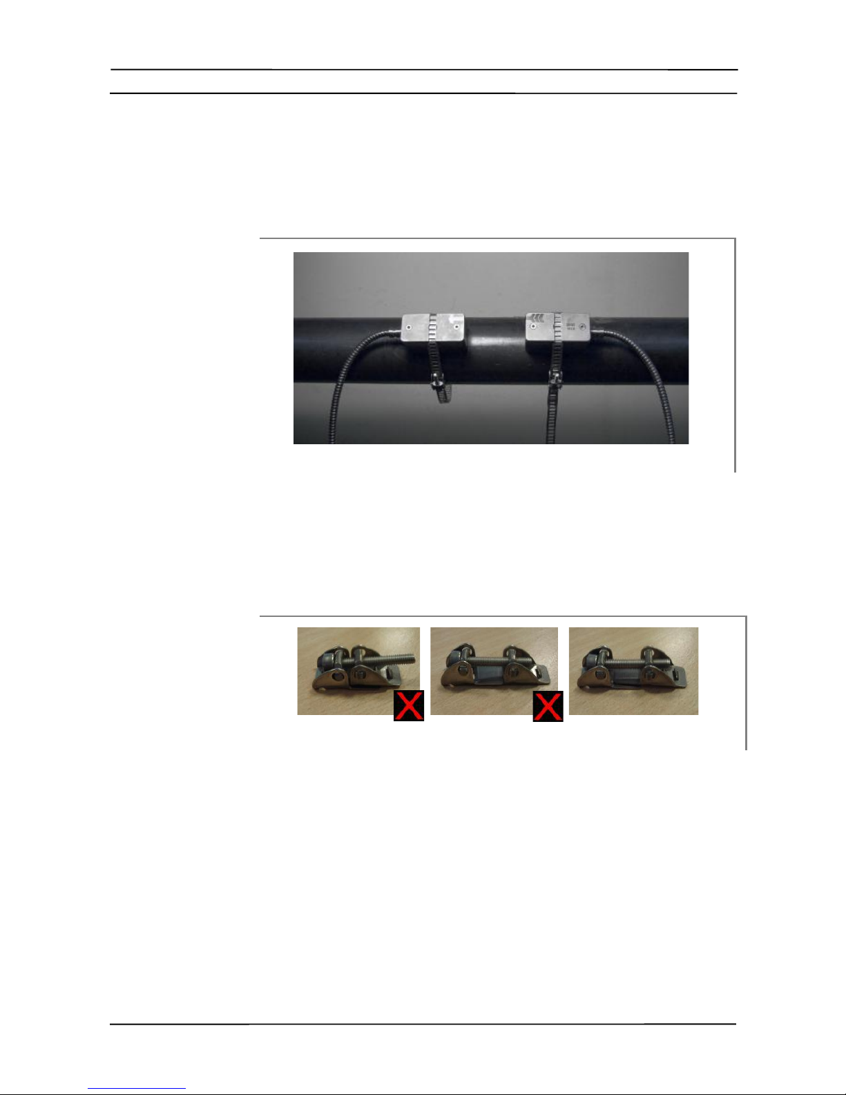
3.7.3 orrect positioning of the sensors
Always mount the transducer pair so that the free front ed es of the sensors face
each other.
There is a different en ravin on the top of each transducer. The transducers are
mounted correctly if the en ravin s on the two transducers form an arrow. The
transducer cables should point in opposite directions.
Later, the arrow, in conjunction with the indicated measured value, will help to de-
termine the direction of flow.
The sensor separation distance is automatically calculated by the flowmeter based
on the parameter entries for pipe outside diameter, wall thickness, linin material
and thickness, medium, process temperature, the sensor type and the selected
number of si nal passes.
3.7.4 Sensor mounting with tension straps
●Cut the tension straps to the appropriate len th.
●Pull at least 2 cm of the tension strap throu h the slot in the clamp and
bend the strap back to secure the clamp to the tension strap.
●Guide the other end of the tension strap throu h the roove on top of the
sensor.
●Place the sensor onto the prepared pipe section.
●Hold the clamp on the transducer with one hand and uide the tension
strap around the pipe.
17
Illustration 7: Metallic mounting straps
Illustration 6: Correct positioning of the sensors
Correct sensor
position
KATflow 100 3 Installation
●Pull the tension strap and uide the free end throu h the clamp so that the
clamp hooks en a e. Sli htly ti hten the screw on the clamp.
●Mount the second sensor in the same way.
●Press the sensors firmly onto the pipe. There should be no air pockets
between the transducer surface and the pipe wall.
●Usin a measurin tape, adjust the sensor separation distance as su es-
ted by the flowmeter. When the sensor positionin screen (Section 3.3) is
displayed, the middle bar allows fine adjustment of the sensor location.
●Ensure that the narrower side of the clip is above and inside the wider side
and that the two sides of the clip do not come into contact while ti htenin ,
as this will prevent the strap from bein correctly tensioned.
18
Illustration 8: Sensor mounting with tension straps and clamps
Illustration 9: Clip arrangement for correct tensioning
KATflow 100 4 Operation
4 Operation
4.1 Switching On/Off
The flowmeter is switched on by connectin the power supply to the instrument.
Disconnectin the external supply switches off the flowmeter.
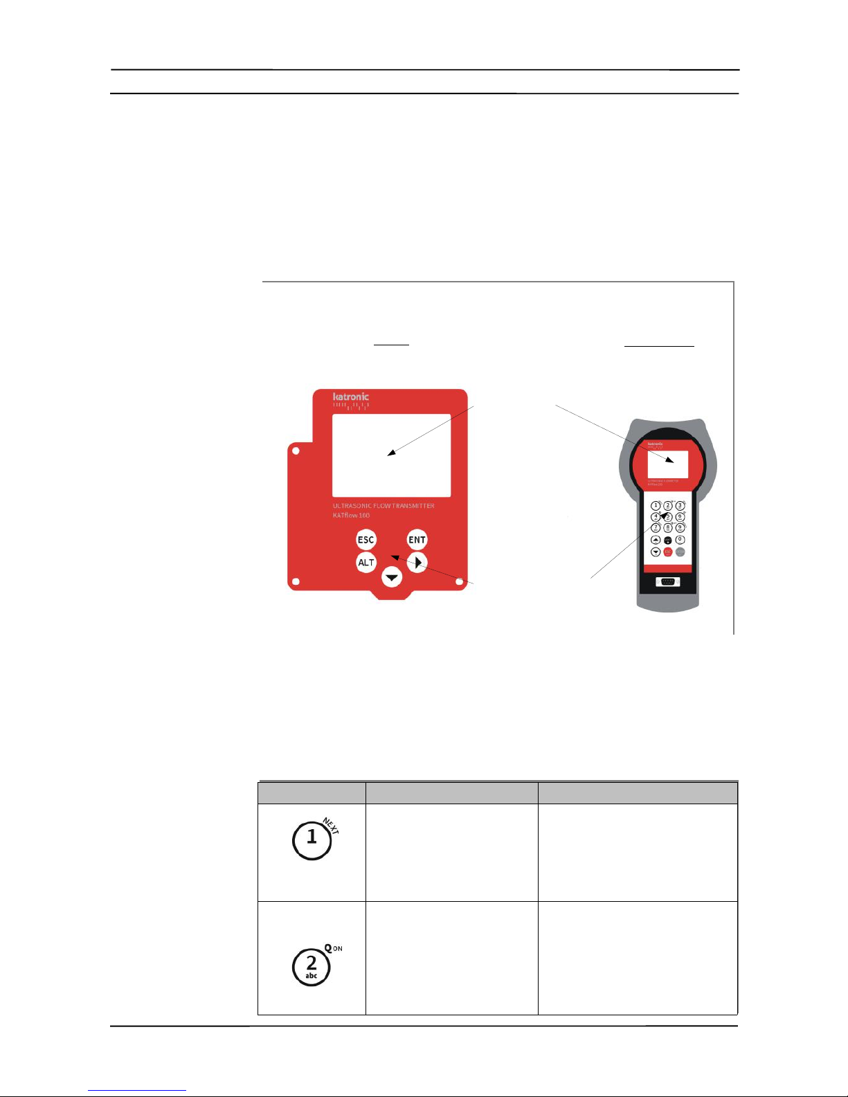
4.2 Keypad and display (where specified)
4.2.1 Keypad key functions (on programmer, where specified)
Key Main function Secondary function
Character entry:
1 (1 short key stroke)
, (2 short key strokes)
. (3 short key strokes)
_ (4 short key strokes)
Show NEXT available dia nostic
screen
Character entry:
A
B
2
/
No function
19
Illustration 10: Keypad and display overview
Display
Keypad
Switching On/Off
KF100 Programmer
Table 3: Menu structure
KATflow 100 4 Operation
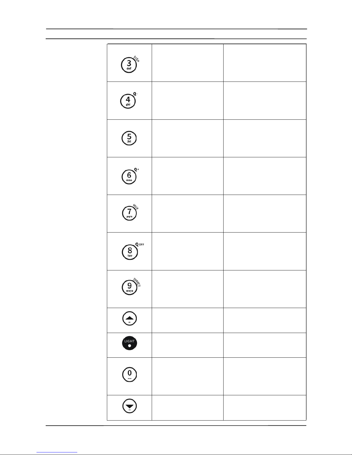
Character entry:
D
E
F
3
?
No function
Character entry:
G
H
I
4
<
No function
Character entry:
J
K
L
5
>
No function
Character entry:
M
N
O
6
$
No function
Character entry:
P
Q
R
S
7
No function
Character entry:
T
U
V
8
*
No function
Character entry:
W
X
Y
Z
9
No function
Move menu/list selection item
UP
Character backspace clear
Character entry:
. (decimal point)
Switch LCD backli ht on/off
Character entry:
0
Space character
+
=
#
No function
Move menu/list selection item
DOWN
Character entry : - (minus si n)
20
Table of contents
Other Thorne & Derrick Transmitter manuals


