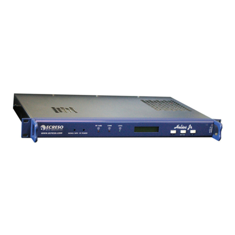
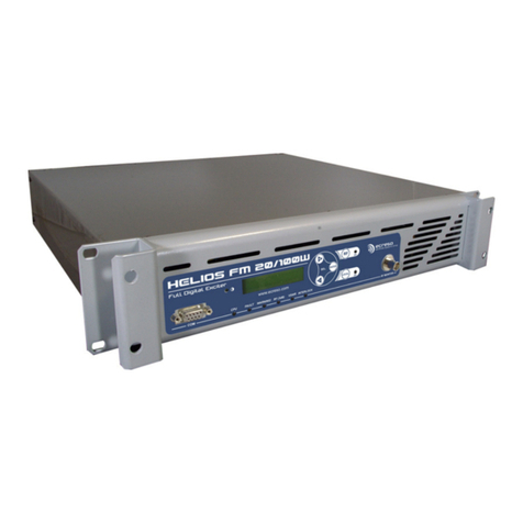
Ecreso HELIOS Series User manual

ecreso WorldCast Systems Group
web: www.ecreso.com - e-mail: contact@ecreso.com
HELIOS TRANSMITTER
20, 50 or 100 W
USER MANUAL
OPTIONS: TUN – CSS - CSS+ - CSSN - TC/S/N - CAN/X – IP/CAN – IP/CAN/X
Date: 2011/01/14
Ref : DOE00012


Head Office : Parc d’activites Kennedy - 20, avenue Neil Armstrong – F-33700 Bordeaux-Merignac (France)
Helios 20, 50 or 100 W, User Manual – 01/2011
Page 3
TABLE OF CONTENTS
1. INTRODUCTION ................................................................................................................................. 6
1.1.Packaging................................................................................................................................... 6
1.2.Guarantee clauses ..................................................................................................................... 7
1.3.Safety instructions ...................................................................................................................... 7
1.4.Radio and television interferences ............................................................................................. 7
2. DESCRIPTION .................................................................................................................................... 8
2.1.General description .................................................................................................................... 8
2.2.HELIOS front panel .................................................................................................................... 9
2.3.HELIOS front panel .................................................................................................................. 10
2.4.Stereo coder back panel .......................................................................................................... 11
2.5.Digital AES coder back panel................................................................................................... 11
2.6.Detailed description of HELIOS ............................................................................................... 12
2.6.1.Synoptic............................................................................................................................... 13
2.6.2.Rack 2U............................................................................................................................... 13
2.6.3.Power supply....................................................................................................................... 13
2.6.4.Main board .......................................................................................................................... 13
2.6.5.RF amplifier block ............................................................................................................... 14
2.6.6.Monitoring card/display ....................................................................................................... 14
2.7.Stereo coder description .......................................................................................................... 15
2.7.1.Input stage .......................................................................................................................... 15
2.7.2.Low pass filter ..................................................................................................................... 15
2.7.3.Pre-emphasis ...................................................................................................................... 15
2.7.4.Mixer.................................................................................................................................... 15
2.7.5.MONO/STEREO configuration............................................................................................ 15
3. TECHNICAL SPECIFICATIONS....................................................................................................... 17
3.1.RF section ................................................................................................................................ 17
3.2.Composite operation ................................................................................................................ 17
3.3.Stereo operation....................................................................................................................... 17
3.4.Mono operation ........................................................................................................................ 17
3.5.AF inputs .................................................................................................................................. 18
3.6.BF output.................................................................................................................................. 18
3.7.HF output.................................................................................................................................. 19
3.8.Power supply............................................................................................................................ 19
3.9.Interface panel.......................................................................................................................... 19
3.10.Environmental .......................................................................................................................... 20
3.11.Physical .................................................................................................................................... 20
3.12.Other......................................................................................................................................... 20
3.13.Spare parts............................................................................................................................... 20
4. USE ................................................................................................................................................... 22
4.1.Mode description ...................................................................................................................... 22
4.1.1.LOCAL mode ...................................................................................................................... 22
4.1.2.DISTANT mode................................................................................................................... 22
4.1.3.RESET function................................................................................................................... 23
4.1.4.STAND-BY mode ................................................................................................................ 23
4.2.Selecting a mode...................................................................................................................... 23
4.3.Anti-yoyo system ...................................................................................................................... 25
4.4.Helios Menu synoptic ............................................................................................................... 26
5. INSTALLATION ................................................................................................................................ 42
5.1.Physical set-up ......................................................................................................................... 42

Head Office : Parc d’activites Kennedy - 20, avenue Neil Armstrong – F-33700 Bordeaux-Merignac (France)
Helios 20, 50 or 100 W, User Manual – 01/2011
Page 4
5.1.1.Input settings (MONO or MPX) ........................................................................................... 42
5.1.2.Pre-emphasis ...................................................................................................................... 43
5.1.3.Input range (MONO and MPX) ........................................................................................... 44
5.2.Physical configuration of the stereo coder ............................................................................... 45
5.2.1.Settings for the Digital Stereo Coder (pre-emphasis) ......................................................... 45
5.2.2.Input range (LEFT and RIGHT Channel) ............................................................................ 46
5.2.3.MONO Function with an analog stereo coder..................................................................... 46
5.3.Physical configuration of the Analog+ stereo........................................................................... 47
5.3.1.Settings for the Analog+ Stereo Coder (pre-emphasis)...................................................... 47
5.3.2.Analog+ Stereo coder transmission mode.......................................................................... 47
5.3.3.Analog+ Stereo coder input range settings......................................................................... 48
5.4.Physical configuration of the AES Digital stereo encoder........................................................ 48
5.4.1.Settings for the AES Digital stereo encoder (pre-emphasis) .............................................. 48
5.4.2.AES Digital stereo encoder transmission mode.................................................................. 49
5.4.3.AES Digital stereo encoder input range settings ................................................................ 49
5.5.Installation ................................................................................................................................ 49
5.6.Adding an optional card............................................................................................................ 50
5.7.Connections ............................................................................................................................. 50
6. SET-UP.............................................................................................................................................. 52
6.1.Recommended test equipment ................................................................................................ 52
6.2.Set-up....................................................................................................................................... 52
6.3.Advanced operation ................................................................................................................. 54
6.3.1.Parameters configuration .................................................................................................... 54
6.3.2.System parameters ............................................................................................................. 56
6.3.3.Checking the Helios settings............................................................................................... 57
6.3.4.Checking the Goliath settings ............................................................................................. 58
6.3.5.Checking the Ines settings .................................................................................................. 59
6.3.6.RF power setting of the set ................................................................................................. 60
6.3.7.DISTANT mode display....................................................................................................... 60
6.4.Indicators and alarms ............................................................................................................... 62
7. SERIAL COMMANDS....................................................................................................................... 63
7.1.Serial commands...................................................................................................................... 63
7.2.Hyper Terminal connection ...................................................................................................... 73
8. REMOTE CONTROL AND REMOTE MONITORING SYSTEM....................................................... 76
8.1.Introduction............................................................................................................................... 76
8.2.RC and RM functions ............................................................................................................... 76
8.2.1."Remote control" functions.................................................................................................. 76
8.2.2."Remote monitoring" functions............................................................................................ 78
8.2.3.Dry-loop activation according to the transmitter status....................................................... 79
8.2.4.Schematic diagram of the inputs and outputs..................................................................... 80
8.2.5.Connectors wiring ............................................................................................................... 81
8.3.Description of RC/RM boards .................................................................................................. 82
8.3.1.Transmitter configuration .................................................................................................... 83
8.3.2.Board presentation.............................................................................................................. 84
8.4.Physical configuration of RC/RM boards ................................................................................. 86
8.4.1.Configuration of inputs/outputs ........................................................................................... 86
8.4.2.Standard configurations ...................................................................................................... 89
8.5.CAN board physical configuration............................................................................................ 90
8.6.Serial port commands .............................................................................................................. 90
8.7.Accessing the embedded web site........................................................................................... 96
8.7.1.Connecting to the embedded web site................................................................................ 96
8.7.2.Viewing the Status .............................................................................................................. 98
8.7.3.Transmitter Configuration.................................................................................................... 99
8.7.4.Maintenance pages........................................................................................................... 100
8.7.5.System Configuration........................................................................................................ 104

Head Office : Parc d’activites Kennedy - 20, avenue Neil Armstrong – F-33700 Bordeaux-Merignac (France)
Helios 20, 50 or 100 W, User Manual – 01/2011
Page 5
8.7.6.Event logs.......................................................................................................................... 115
8.7.7.About ................................................................................................................................. 116
9. MAINTENANCE .............................................................................................................................. 117
9.1.Preventive maintenance......................................................................................................... 117
9.2.Repair..................................................................................................................................... 117
10. INTERFACES................................................................................................................................ 119
10.1.Stereo coder card (Ref: CSS) ................................................................................................ 119
10.2.Analog+ Stereo Coder card (Ref: CSS+) ............................................................................... 119
10.3.Digital stereo coder card (Ref: CSSN) ................................................................................... 120
10.4.Standard RC/RM card (Ref: TS05 or TS24) .......................................................................... 120
10.5.Digital RC/RM card (Ref: TN05 or TN24)............................................................................... 121
10.6.CAN card (Ref: CAN) ............................................................................................................. 121
10.7.CAN/X card (Ref: CAN/X) ...................................................................................................... 122
10.8.IP/CAN card ........................................................................................................................... 122
10.9.IP/CAN/X card ........................................................................................................................ 123
10.10.OEM................................................................................................................................... 123
GLOSSARY......................................................................................................................................... 124
FOR MORE INFORMATION............................................................................................................... 127
This manual suits for next models
3
Table of contents
Other Ecreso Transmitter manuals
Popular Transmitter manuals by other brands

Geo
Geo Web Pack quick start guide

Inovonics
Inovonics EchoStream EN1210W installation instructions

IKONNIK
IKONNIK KA-6 quick start guide

Rohde & Schwarz
Rohde & Schwarz SR8000 Series System manual

Audio Technica
Audio Technica UniPak ATW-T93 Installation and operation

NIVELCO
NIVELCO EasyTREK SCA-300 Series Programming manual


