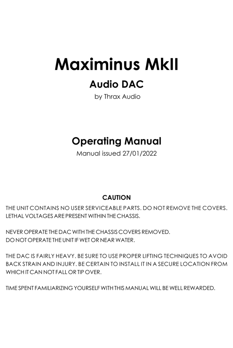
Thrax Audio Maximinus User manual

Maximinus
Audio DAC
by Thrax Audio
Owner’s Manual
Manual issued 15/01/2014
CAUTION
THE UNIT CONTAINS NO USER SERVICEABLE PARTS. DO NOT REMOVE THE COVERS.
LETHAL VOLTAGES ARE PRESENT WITHIN THE CHASSIS.
NEVER OPERATE THE DAC WITH THE CHASSIS COVERS REMOVED.
DO NOT OPERATE THE UNIT IF WET OR NEAR WATER.
THE DAC IS FAIRLY HEAVY. BE SURE TO USE PROPER LIFTING TECHNIQUES TO AVOID
BACK STRAIN AND INJURY. BE CERTAIN TO INSTALL IT IN A SECURE LOCATION FROM
WHICH IT CAN NOT FALL OR TIP OVER.
TIME SPENT FAMILIARIZING YOURSELF WITH THIS MANUAL WILL BE WELL REWARDED.

CONTENTS
2
1. Important Safety Instructions …...................………….................................... 3
2. Introduction ………........................................................................................… 4
3. Specifications ……........................................................................................… 4
4. Unpacking and Installation
- Unpacking ……....................................................................................… 5
- Installation ……....................................................................................… 5
5. Front Panel ……..............................................................................................… 6
6. Back Panel
- Inputs …..…...........................................................................................… 7
- Outputs ………......................................................................................… 7
- Power Connector, Main Switch, Fuses, Input Voltage Selector .. 7
7. Operation ………...........................................................................................… 8

READ ALL INSTRUCTIONS: All the safety and operating instructions of your Thrax Audio
equipment should be read before power is applied to the equipment.
RETAIN OWNER'S MANUAL: These safety and operating instructions should be retained
for future reference.
HEED WARNING: All warnings on the unit and in the operating instructions should be
adhered to.
FOLLOW INSTRUCTIONS: All operating and use instructions should be followed.
CLEANING: Unplug the unit from the wall outlet before cleaning.
VENTILATION: Do not install near any heat sources such as radiators, heat registers,
stoves, or other devices (including amplifiers). The unit should not be installed in a
built-in location such as a bookcase or rack unless proper ventilation is provided.
GROUNDING: Do not defeat the safety purpose of the grounding-type plug. A
grounding-type plug has two blades and a third grounding prong. The third prong is
provided for your safety. If the provided plug does not fit into your outlet, consult an
electrician for replacement of the obsolete outlet.
POWER CORD PROTECTION: Protect the power cord from being walked on or pinched
particularly at plugs, convenience receptacles and the point where they exit from
the unit.
LIGHTNING: Unplug this unit during lightning storms or when unused for long period of
time.
SERVICING: Refer all servicing to qualified service personnel. Servicing is required
when the unit has been damaged in any way, such as if the power-supply cord or
plug is damaged, liquid has been spilled inside the appliance or it has been exposed
to moisture, the appliance does not operate normally, or has been dropped.
DO NOT OPEN THE CABINET: There are no user serviceable components inside this
product. Opening the cabinet may present a shock hazard and any modification to
the product will void your warranty.
WARNING: To reduce the risk of fire or electric shock, do not expose this unit to rain or
moisture.
IMPORTANT SAFETY INSTRUCTIONS
3

The Maximinus is a universal DAC with some advanced DSP functions supporting up to
32bit/384kHz audio data rates.
Features
Versatile I/O: 7 digital inputs covering all popular interface formats
Two sets of analogue outputs - RCA and XLR
The DSP functions: Re-Clocking for synchronizing incoming data to internal clock
reference generator
Upsampling incoming data to 32bit 356/384kHz – two algorithms
Selection of four digital filters with different impulse response
EMI/RFI protection: Transformer decoupled I/O and power supplies
True balanced interface
INTRODUCTION
• Inputs
- 2 x COAX (RCA) connectors. Limited to 384 kHz, 24 bit data
- 2 x AES/EBU (XLR) connectors
- 2 x TOSLINK (optic) connectors. This format has limited bandwidth
and works for maximum sample rates of 192 kHz
- 1 x USB (optional)
• Output
- 1 pair unbalanced RCA connectors
- 1 pair balanced XLR connectors
• Power supply ……………….............................................…….. 115 or 230 V
• Power consumption ……….......................................................…….......... 30W
• Dimensions ………………...............................…….. WxDxH - 432x400x120 mm
• Weight ………………...........................................................................…….. 12Kg
• Finish …….........................................…….. Black or Silver anodized aluminium
SPECIFICATIONS
4

This section describes the unpacking and installation procedures for your new
component.
Unpacking
All Thrax Audio shipping boxes have been specially designed to protect their contents
and special care has been taken to prevent damage under normal shipping
conditions. Mishandling should be evident upon inspection of the shipping container.
Carefully remove your new component from its packing and examine it closely for
signs of shipping damage. We strongly recommend saving all original packing to
protect your component from damage should you wish to store it or ship it at a later
date.
Installation
• BE CERTAIN TO INSTALL THE UNIT IN A SECURE LOCATION FROM WHICH IT CANNOT
FALL OR TIP OVER
• Provide adequate ventilation - the chassis will become warm in normal use. Do not
operate on carpet or any other surface that might block air flow
• Do not allow the chassis to touch any metal parts, such as the frame of an
equipment rack. This might create a parallel ground path that could degrade the
sound of your system
• Connect the input and output cables. Input connection is via COAX , AES/EBU
TOSLINK or USB. Output can be via RCA or XLR jacks
IMPORTANT: READ THE SECTIONS “BACK PANEL”
WARNING: The unit should be operated only at rated voltage, indicated on the power
connector. If you are not sure what is the mains voltage supplied to your home,
consult with your unit dealer.
Connect the power supply to the power source indicated on the rear panel. Avoid
power conditioners that float the ground pin. ALWAYS connect power cord to
component before plugging it into an AC outlet, and make sure that unit’s main
switch is set to the „off” position before making the final connection. For best
performance, try to route the power cord away from signal cables.
Pay close attention to power quality, and be aware that different power cords can
alter the sound.
UNPACKING AND INSTALLATION
5

“ON/OFF” Button:
Switches the unit “ON” and “OFF”. See OPERATION SECTION for details
“MUTE” Button:
This button toggles between mute and normal volume modes. When the indicator
above the mute button is green the system is muted
“MENU” Button:
Switches between menu and normal operation
“ENTER” Button
Validates the option selected
“MENU” Knob
Scrolls through the menu
LED Display
Shows the input selected, the signal sample/bit rate and the menu options. This
display is auto dimmable – turns off in few seconds if no control is operated. It turns
on automatically at power up, in case the input signal changes or user menu is
selected.
FRONT PANEL
“ON/OFF” Button
“MUTE” Button
“MENU” Button
MENU” Knob
“ENTER” Button
“LED Display
Fig. 1
6

IEC Power Connector, Main Switch, Fuses and Input Voltage Selector:
There are fuses located in the IEC power connector on the back panel. For 230
volts operation a 0.63 amperes “Slow Blow” fuse is used. For 115 volts operation the
fuse should be 1.25 amperes. If power does not come on, contact your authorized
service representative.
Inputs:
2 x COAX jacks, labeled 1 and 2, accommodate signal from digital sources, good
for short runs and lower frequencies
2 x TOSLINK inputs, labeled OPT 1 and OPT 2, provide ground isolation between the
units and noise immunity over long runs
2 x AES/EBU inputs, labeled AES 1 and AES 2 to accommodate high quality signal,
that uses professional protocol
1 x USB input (optional)
Currently a USB – input is available to accommodate digital signal from a
computer source
Outputs:
Two sets of analog output jacks are provided – a pair single-ended RCA outputs
and a pair of balanced XLR outputs.
The switch between them activates the selected output.
7
BACK PANEL
--------
COAX Inputs
TOSLINK Inputs
AES/EBU Inputs
RCA Outputs
SWITCH RCA/XLR
XLR Outputs
Input Voltage Selector
Fig. 2
USB (optional)

To switch the DAC on press the “ON/OFF” button on the front panel. The red standby
indicator blinks green for approx 10 sec. whilst the unit warms up. When ready, the
indicator will stop blinking, turn green, and the last active source will be selected
automatically. The front panel display will be on while the unit is executing a command
and then turns off after a short timeout period. When an input signal is detected, the
frequency and bit depth will be read out on the display.
Re-clocking
– Enable this function in the user menu (see “Menu structure” below) . This very
important feature of the DAC allows for all jitter to be removed from the input source.
Data is read onto the device’s memory and then independently read out using a ultra
stable clock. When enabled, this option will completely replace the incoming clock with
an ultra low jitter TCXO based clock. The DSP monitors the incoming sample frequency
and detects standard sample rate signals - 44.1 kHz, 48 kHz, 88.2 kHz, 96 kHz, 176.4 kHz, 192
kHz, 352.8 kHz and 384 kHz. The on-board clock then completely replaces the incoming
clock. The source’s clock is used for other sampling frequencies. The DSP allocates a
huge internal FIFO buffer (1/2 second at 44.1), that stores the incoming audio to
decouple the incoming and outgoing data streams. Long absolute digital silences in the
music stream, such as between tracks and during pauses, are selectively shortened or
lengthened by the DSP to maintain data synchronization. This results in a significant delay
between the audio source and the analog audio. You will not normally notice this delay
unless video is synchronized with the audio. For this reason you may want this feature to
be turned off when watching video, or the video might be delayed.
Up-sampling
– Enable this function in the user menu (see “Menu structure” below) thus all input signals
will be up-sampled to max resolution 32/352 or 32/384 depending on input signal. To
achieve this, a digital filter takes a look at a window of the music being played, and
because that music was received from a digital source, there are holes in it, between
data bytes. The filter looks at the shape of the signal in the window and tries to figure out
what the missing data is. The bigger the window, the better a job it does, and the bigger
processor is needed. You can select which up-sampling algorithm to use (UPS F1 or F2 in
the User Menu) in the process of filling in the gaps between the data.
Digital Filter
– The digital filter is necessary because mirrored image frequencies created during the
conversion process must be removed. If the DAC did not have a digital filter, an analog
filter with an aggressive response must remove these image frequencies. Analog filters
seriously damage the signal by corrupting the original phase of the sound and cannot
fully remove the high frequency images. This results in harsh or rolled off high frequencies
and poor soundstage focus.
OPERATION
8

9
Our DAC offers a choice of 4 digital filters (F1, F2, F3 and F4), selectable in the User Menu.
Each option provides a distinct, glorious listening experience. You may favor one or the
other, or enjoy changing the filter response to suit the music you listen to.
To turn off the DAC press the ON/OFF button. All the unit circuitry will be turned off for
minimum power consumption leaving only a small STANDBY circuit running. However, if
you are not going to use the DAC for a long period we recommend turning it off, using the
power switch on the back panel, to save power.
As with all high fidelity products, the sound characteristic changes somewhat as it warms
up. Best sound will be achieved after about 15 minutes of operation.
Any time that the Maximinus DAC has not been used for a few weeks the sound may be
different. This is also normal for high resolution audio equipment. Optimum sound should
return after a few hours of operation, preferably with an audio signal.
Note that although your Thrax Audio System has been run for 72 hours at the factory, it will
continue to ”break in” for approximately 150 hours. Also be aware that many components
display the need for a new break in period after being transported in unheated cargo aircraft.
Menu structure
1. Phase +/- – switches absolute phase of the signal
2. Reclock ON/OFF – turns the reclocking feature on/off (and uses the internal
clock generator)
3. Upsa ON/OFF – turns the upsampling feature on/off (when on Upsamples all input
signals to max resolution 32/352 or 32/384 depending on input signal)
4. UPS F1/F2 – selects an upsampling algorithm
5. Filter F1/F2/F3/F4 – selects a digital filter. Listen and select the filter
that best suits the original recording and the rest of your audio system
Options
Digital audio is developing at a very fast pace and to protect your investment in our state
of the art DAC we have provided 2 option slots that can accommodate whatever new
technology or interface becomes standard.
Currently USB is a de facto standard for interfacing a computer to audio DAC. There are a
number of implementations and options for those as well. We constantly monitor the state
of development of all and will offer the best implementations as options for your DAC.
There are a number of other technologies that we are currently monitoring and as soon
as any of them have matured we will implement them as options.
Please check our website regularly for updates.
OPERATION
9

NOTES
Table of contents
Other Thrax Audio Media Converter manuals
Popular Media Converter manuals by other brands

Costar Video Systems
Costar Video Systems CRT1200EN user manual

Uplink
Uplink 301442/20160413SZ090 user manual

Crystal Vision
Crystal Vision UP-DOWN-VF Series user manual

Planet
Planet POE-151 user manual
Jensen
Jensen ISO-MAX DB-2RM-WP user guide
Blackmagicdesign
Blackmagicdesign Broadcast Converter Operation manual
