THRUSH S2R-T34 Technical specifications


Thrush Aircraft Inc Model S2R-T34 MANUAL
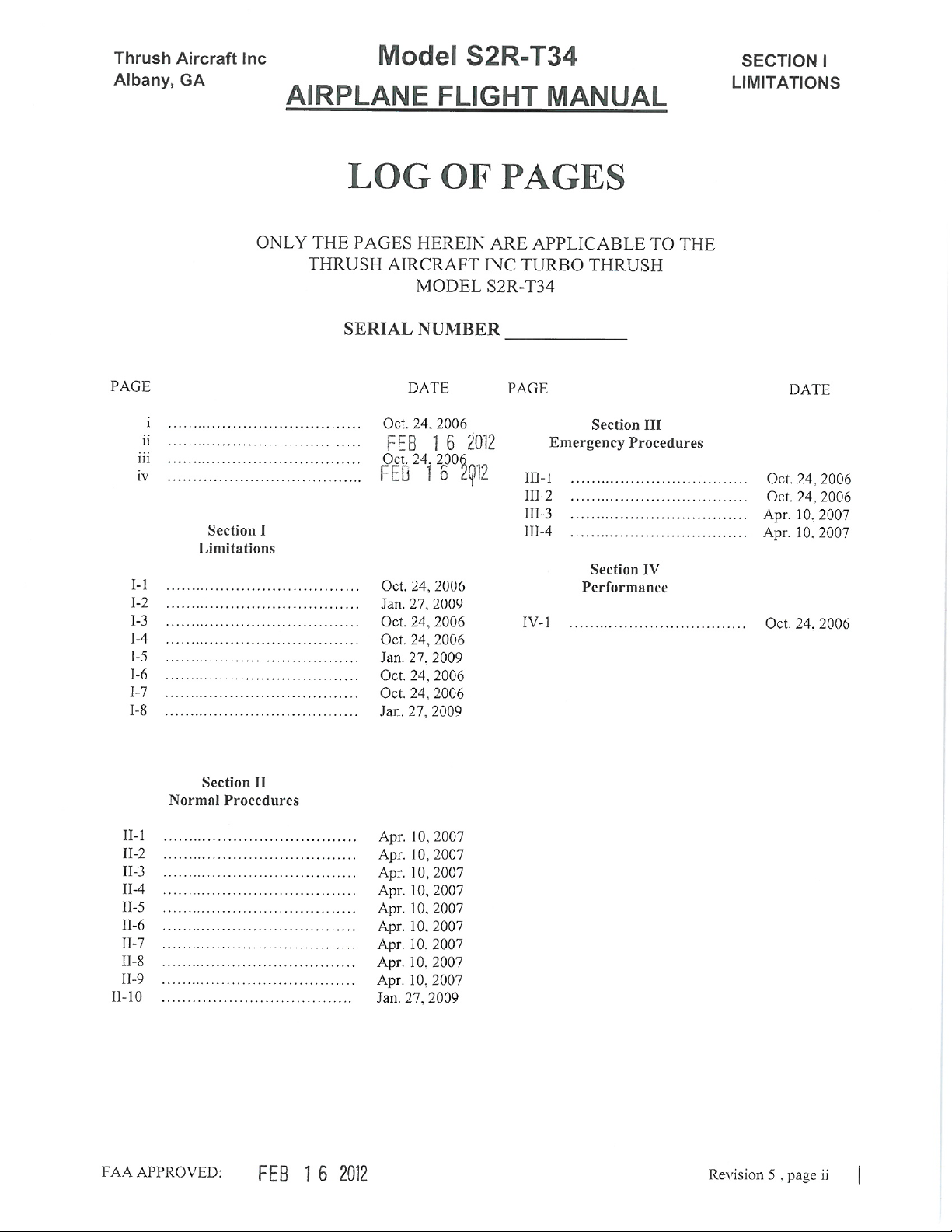
Albany, GA AIRPLANE FLIGHT MANUAL ORGANIZATION
FAA APPROVED: Oct. 24, 2006 Revision 2, page i
SECTION I-----------------------------------------------------LIMITATIONS
SECTION II-------------------------------------- NORMAL PROCEDURES
SECTION III--------------------------------EMERGENCY PROCEDURES
SECTION IV-------------------------------------------------PERFORMANCE


Thrush Aircraft Inc Model S2R-T34 SECTION I
Albany, GA AIRPLANE FLIGHT MANUAL LIMITATIONS
FAA APPROVED: Oct. 24, 2006 Revision 2, SECTION I-1
SECTION I
LIMITATIONS
TABLE OF CONTENTS
Subject page | Subject page
POWER PLANT................................................... I-1 | WEIGHT AND CENTER OF GRAVITY ...........I-5
INSTRUMENT MARKINGS ............................... I-3 | MANEUVERS .....................................................I-6
AIRSPEED LIMITATIONS ................................. I-4 | TYPES OF OPERATION....................................I-6
ALTITUDE LIMITATIONS................................. I-4 | GROUND OPERATION .....................................I-6
FLIGHT LOAD FACTORS.................................. I-4 | PLACARDS.........................................................I-6
NOISE ABATEMENT.......................................... I-4
POWERPLANT:
ENGINE:
STANDARD: Pratt & Whitney Canada PT6A-34AG
OPTIONAL: Pratt & Whitney Canada PT6A-34
Pratt & Whitney Canada PT6A-36 (Dry Configuration Only)
Pratt & Whitney Canada PT6A-41, -41AG
Pratt & Whitney Canada PT6A-42
FUEL:
JET A, JET B, JP-4, JP-5. (If jet fuel is not available, aviation gasoline, MIL-G-5572, all grades,
may be used for a maximum of 150 hours between overhauls).
ENGINE LIMITS: PT6A-34AG, -34, -36 (PT6A-34AG shown)
POWER
SETTING SHP TORQUE
(PSI) ITT
(ºC) NG
(%) NP
(RPM)
OIL
PRESS.
(PSIG)
OIL
TEMP.
(ºC)
Takeoff & Max
continuous 750 64.5***
58.7**** 790 101.6 2200 85 to 105 10 to 99
Max Climb 700 60.2***
54.7**** 765 101.6 2200 85 to 105 0 to 99
Max Cruise 700 60.2***
54.7**** 740 2200 85 to 105 0 to 99
Idle 685 50 40 Min. -40 to 99
Starting 1090* -40 Min.
Acceleration 68.4** 850* 102.6* 2420 0 to 99
Max. Reverse 750 64.5***
GENERAL NOTE: The operating parameters in this Table are individual limits for each engine
parameter and do not necessarily apply simultaneously.
61.4**** 790 101.6 2100 85 to 105 0 to 99
*These values are time limited to two (2) seconds.
**These values are time limited to twenty (20) seconds.
***Torque limit for Max NP= 2000 RPM
****Torque limit for NP= 2200 RPM

Thrush Aircraft Inc Model S2R-T34 SECTION I
Albany, GA AIRPLANE FLIGHT MANUAL LIMITATIONS
FAA APPROVED: Jan. 27, 2009 Revision 4, SECTION I-2
ENGINE LIMITS: PT6A-41AG, -41, -42 (PT6A-41AG shown)
***
TORQUE
POWER
SETTING SHP
GENERAL NOTE: The operating parameters in this Table are individual limits for each engine
parameters and do not necessarily apply simultaneously.
(PSI)
ITT
(ºC) NG
(%) NP
(RPM)
OIL
PRESS.
(PSIG)
OIL
TEMP.
(ºC)
Takeoff & Max
continuous 750 64.5 750†101.5 2000 105 to
135††† 0 to 99
Max Climb 700 60.2 725†† 101.5 2000 105 to
135††† 0 to 99
Max Cruise 700 60.2 725†2000 105 to
135††† 0 to 99
Idle 50 60 Min. -40 to 99
Starting 1000* -40 Min.
Acceleration 68.4* 850 102.6 2205 99 to 104**
Max. Reverse 750 64.5 750 101.5 2000 105 to
135††† 0 to 99
*These values are time limited to five (5) seconds.
**Time limited to ten (10) minutes at any operating condition.
***Torque limit shown for NP= 1600-2000 RPM.
†For PT6A-42 790ºC.
††For PT6A-42 765ºC.
†††For PT6A-42 100 to 135
STARTER: Maximum starter engagement duration is 30 Seconds followed by a 60 Seconds
cool down period. Total of 3 cycles to be followed by 30 minutes starter cool
down.
AIR STARTS: Normal air starts are approved from sea level to 12,000 feet altitude and from 80
MPH to 126 MPH air speed. See the Emergency Procedures in Section III.
PROPELLER: Hartzell Hub Model HC-B3TN-3C (or HC-B3TN-3D) with Blade Model T-10282,
Diameter 102.5 inches maximum, 92.5 inches minimum or optional Blade Model
T-10282 (N) +4, Diameter 106.5 inches maximum, 98.0 inches minimum.
REVERSE POWER: Do not use in flight
P-3 HEATER: Regardless of fuel type used, the P-3 heater switch must be turned on (if installed)
for flight and ground operations when the free air temperature is below 40 Degrees
F.

Thrush Aircraft Inc Model S2R-T34 SECTION I
Albany, GA AIRPLANE FLIGHT MANUAL LIMITATIONS
FAA APPROVED: OCT 24, 2006 Revision 2, SECTION I-3
INSTRUMENT MARKINGS:
Limits Features Meaning
OIL TEMP ( °C)
-40
-40 to10
10 to 99
99
Red Radial
Yellow Arc
Green Arc
Red Radial
MINIMUM
CAUTION
NORMAL
MAXIMUM
OIL PRESSURE (PSI) PT6A-34AG, -34, -36
40
40 to 85
85 to 105
105
Red Radial
Yellow Arc
Green Arc
Red Radial
MINIMUM
CAUTION
NORMAL
MAXIMUM
OIL PRESSURE (PSI) PT6A-41AG,-41
60
60 to 105**
105 to 135
135
Red Radial
Yellow Arc
Green Arc
Red Radial
MINIMUM
CAUTION
NORMAL
MAXIMUM
OIL PRESSURE (PSI) PT6A-42
60
60 to 100***
100 to 135
135
Red Radial
Yellow Arc
Green Arc
Red Radial
MINIMUM
CAUTION
NORMAL
MAXIMUM
FUEL PRESSURE (PSI) 5
5 to 50
50
Red Radial
Green Arc
Red Radial
MINIMUM
NORMAL
MAXIMUM
ITT (°C) PT6A-34AG, -34, -36 400 to 790
790 Green Arc
Red Radial NORMAL
MAXIMUM
ITT (°C) PT6A-41AG, -41 400 to 750
750 Green Arc
Red Radial NORMAL
MAXIMUM
ITT (°C) PT6A-42 400 to 800
800 Green Arc
Red Radial NORMAL
MAXIMUM
TORQUE (PSI) PT6A-34AG, -34, -36
0 to 58.7
58.7*
64.5
Green Arc
Red Radial
Red Diamond
NORMAL
MAXIMUM
Max @
2000RPM
TORQUE (PSI)
PT6A-41AG, -41, -42 0 to 64.5
64.5 Green Arc
Red Radial NORMAL
MAXIMUM
PROPELLER RPM (NP)
PT6A-34AG, -34, -36 0 to 2200
2200 Green Arc
Red Radial NORMAL
MAXIMUM

Thrush Aircraft Inc Model S2R-T34 SECTION I
Albany, GA AIRPLANE FLIGHT MANUAL LIMITATIONS
FAA APPROVED: OCT 24, 2006 Revision 2, SECTION I-4
INSTRUMENT MARKINGS (Continued)
Limits Features Meaning
PROPELLER RPM (NP)
PT6A-41AG, -41, -42 0 to 2000
2000 Green Arc
Red Radial NORMAL
MAXIMUM
GAS GENERATOR SPEED (% NG) 50 to 101.6
101.6 Green Arc
Red Radial NORMAL
MAXIMUM
AIRSPEED
66 to 123 MPH CAS
70 to 126 MPH CAS
126 to 159 MPH CAS
159 MPH CAS
White Arc
Green Arc
Yellow Arc
Red Radial
Flaps Operating Range
Normal Operating Range
Caution Range
Never Exceed
* In addition to a red radial limit marker at 58.7 PSI, the torque meter is marked with a red diamond at 64.5
PSI. (58.7 PSI is the torque limit for 2200 RPM, the normal takeoff RPM. 64.5 PSI is the torque limit for
2000 RPM, an optional RPM setting for in-flight use.)
** The 60-105 oil pressure caution range is for idling and for emergency completion of a flight using 36 PSI
torque or below.
*** The 60-100 oil pressure caution range is for idling and for emergency completion of a flight using 36 PSI
torque or below.
AIRSPEED LIMITATIONS:
Never Exceed Speed VNE – 159 MPH
Maximum Structural Cruising - VNO – 126 MPH
Maneuvering Speed – VA– 126 MPH
Flap Extended Speed – VFE – 123 MPH
Maximum Dump Speed – 120 MPH
Maximum Crosswind Velocity – 15 MPH
All airspeeds are given in Calibrated Air Speeds.
ALTITUDE LIMITATIONS:
Maximum approved altitude is 12,000 feet.
FLIGHT LOAD FACTORS:
Design Load Factors - Flap Up; 3.8 Positive, 1.9 Negative
Design Load Factors - Flap Down; 2.4 Positive, 0.0 Negative
NOISE ABATEMENT:
This airplane has not been shown to comply with the noise limits in FAR 36 and must be
operated in accordance with the noise operating limitation prescribed under FAR §91.815.

Thrush Aircraft Inc Model S2R-T34 SECTION I
Albany, GA AIRPLANE FLIGHT MANUAL LIMITATIONS
FAA APPROVED: Jan. 27, 2009 Revision 4, SECTION I-5
WEIGHT AND CENTER OF GRAVITY:
NOTE
Datum is the leading edge of the wing.
Maximum Weight – 6000 pounds
C.G. Range for SINGLE & DUAL COCKPIT
* Forward Limit at 6000 pounds is 26.5 inches AFT of Datum.
* Forward Limit at 4000 pounds is 24.0 inches AFT of Datum.
* AFT Limit is 29.0 inches AFT of Datum (Normal Category).
Straight Line variation in the Forward Limit between 4000 pounds and 6000 pounds.
7,000
6,500
6,000
5,500
5,000
4,500
4,000
3,500
3,000
23.0 23.5 24.0 24.5 25.0 25.5 26.0 26.5 27.0 27.5 28.0 28.5 29.0 29.5 30.0
4,000 lbs
@ 24.0 in
6,000 lbs
@ 26.5 in
4,000 lbs
6,000 lbs
@ 29.0 in
Center of Gravity - in. aft of datum
Airplane Weight - lbs
Thrush S2R-T34 Single & Dual Cockpit
Weight & Center-of-Gravity Envelope
Normal Catagory

Thrush Aircraft Inc Model S2R-T34 SECTION I
Albany, GA AIRPLANE FLIGHT MANUAL LIMITATIONS
FAA APPROVED: OCT 24, 2006 Revision 2, SECTION I-6
NOTE
It is the responsibility of the airplane owner and the
pilot to insure that the airplane is properly loaded. See
the aircraft’s Weight and Balance Sheet for loading
information.
MANEUVERS:
NORMAL CATEGORY
Flight maneuvers include steep turns, chandelles, and lazy-eights in which bank angles do
not exceed 60 degrees and pitch angles do not exceeds 30 degrees. Gradual entry rate
stalls are also approved. Acrobatic maneuvers and intentional spins are PROHIBITED.
TYPES OF OPERATION:
The Model S2R-T34 aircraft is approved for day and night VFR flight conditions. Flight
into known icing conditions is PROHIBITED.
GROUND OPERATION:
Ground operation is approved at ground idle power with the propeller feathered and with
no time limits. The pilot should monitor the engine instruments for operation within
limits during all ground operations.
PLACARDS:
A. Located on Right Hand lower instrument panel:
“THIS AIRPLANE MUST BE OPERATED AS A NORMAL CATEGORY AIRPLANE IN
ACCORDANCE WITH THE OPERATING LIMITATIONS STATED IN THE FORM OF
PLACARDS AND THE AIRPLANE FLIGHT MANUAL. NO ACROBATIC MANEUVERS,
INCLUDING SPINS APPROVED. DESIGN MANEUVERING SPEED-126 MPH. MAX.
FLAP-DOWN SPEED-123 MPH. MAX. CROSSWIND VELOCITY,
LANDING-15 MPH. USABLE TANK CAPACITY 114 GALLONS EACH SIDE.”
“THE OPERATION OF THIS AIRPLANE IS LIMITED TO DAY AND NIGHT VFR
CONDITIONS. FLIGHT INTO KNOWN ICING CONDITIONS IS PROHIBITED.”
“NO SMOKING”
“SULFUR DUSTING IS PROHIBITED UNLESS SPECIAL FIRE PREVENTION MEASURES
HAVE BEEN INCORPORATED IN AIRCRAFT.”
“PUSH STICK FORWARD TO UNLOCK TAILWHEEL.”
“TAKING OFF IN VISIBLE MOISTURE BELOW 40°F IS PROHIBITED.”

Thrush Aircraft Inc Model S2R-T34 SECTION I
Albany, GA AIRPLANE FLIGHT MANUAL LIMITATIONS
FAA APPROVED: OCT 24, 2006 Revision 2, SECTION I-7
B. Located near Park Brake Valves:
“PARK BRAKE – ON, DEPRESS PEDALS AND PULL LEVER. OFF, DEPRESS PEDALS”
C. Located on Forward Lower Corner of Each Door Side Window:
“DO NOT OPEN DOOR IN FLIGHT”
“DO NOT OPEN DOOR ON THE GROUND WITH ENGINE RUNNING UNLESS HEADED
OUT OF THE WIND WITH THE PROPELLER FEATHERED”
D. Located adjacent to the torque meter:
“MAXIMUM TORQUE IS 58.7 PSI AT 2200 RPM OR 64.5 PSI AT 2000 RPM WITH
STRAIGHT LINE VARIATION BETWEEN THESE POINTS”
E. At both fuel filler caps:
“FUEL – 115 GAL. CAP. JET A, JET B, JP-4 & JP-5”
F. Located on upper instrument panel:
“DO NOT USE REVERSE POWER IN FLIGHT. AT HIGH TAXI
SPEEDS USE REVERSE POWER ONLY IF THE TAIL WHEEL IS
LOCKED AND FIRMLY ON THE GROUND.”
WARNING
G. Located on cockpit wall (If P-3 Heater is installed):
WARNING
“REGARDLESS OF FUEL TYPE USED, THE P-3 HEATER SWITCH
MUST BE TURNED ON FOR FLIGHT AND GROUND OPERATIONS
WHEN THE FREE AIR TEMPERATURE IS BELOW 40 DEGREES F.”
H. Located on top of hopper
“HOPPER CAPACITY 3336 LBS.”
I. Located on Left Hand Lower instrument panel:
“FILTER CONDITION – FLIGHT IN RED IS PROHIBITED.”
J. Located on the fuel gauge:
“USABLE FUEL 114 U.S. GAL. FUEL ABOVE 82 GAL. IS UNGAGEABLE”.

Thrush Aircraft Inc Model S2R-T34 SECTION I
Albany, GA AIRPLANE FLIGHT MANUAL LIMITATIONS
FAA APPROVED: Jan. 27, 2009 Revision 4, SECTION I-8
K. Located on inside of baggage door: (Single Cockpit Only)
“60 LBS. MAXIMUM BAGGAGE”
L. Located on right hand side panel, rear cockpit: (Dual Cockpit Only)
“PASSENGER OR CARGO 200 LBS MAXIMUM”
M. Located at each door latch:
OPEN or OPEN
N. Located on the Outside of the rear cockpit door: (Dual Cockpit Only)
OPEN
O. Located at each door knockout panel:
“PUSH OUT AND LIFT HINGE PIN FOR EMERGENCY EXIT”
P. Located (inverted) at each door hinge pin:
“PULL HINGE PIN ÆFOR EMERGENCY EXIT”
Q. Located on face of Fuel Shut-off Valve handle bracket:
S/N 273 through 277 and 279:
“FUEL, 228 GAL USEABLE
ON OFF”
S/N 278, 280 and up:
“FUEL, 228 GAL USEABLE
ON OFF
PUSH BUTTON TO TURN”
R. Located on upper instrument panel (Dual Cockpit Only):
100# REMOVABLE BALLAST @ FS – 85.0
MUST BE INSTALLED IF PASSENGER OR
MORE THAN 50# OF CARGO IS ON BOARD

Thrush Aircraft Inc Model S2R-T34 SECTION II
Albany, GA NORMAL PROCEDURES
AIRPLANE FLIGHT MANUAL
SECTION II
NORMAL PROCEDURES
TABLE OF CONTENTS
Subject page | Subject page
DEFINITIONS................................................II-1 | CLIMB ..........................................................II-8
VISUAL INSPECTION..................................II-2 | GLIDE AND APPROACH ...........................II-8
BEFORE STARTING ....................................II-5 | GO AROUND ...............................................II-8
STARTING ENGINE.....................................II-5 | LANDING.....................................................II-8
DRY MOTORING RUN................................II-6 | AFTER CLEARING THE RUNWAY..........II-9
TAXI...............................................................II-7| ENGINE SHUTDOWN ................................II-9
BEFORE TAKE-OFF.....................................II-7 | SECURING THE AIRCRAFT......................II-9
TAKE-OFF.....................................................II-7
DEFINITIONS:
Personal injury or loss of life could result if the operating procedures
and techniques are not followed carefully.
Damage to equipment could result if the operating procedures and
techniques are not followed carefully.
NOTE This is used when it is essential to emphasize an operating procedure or
technique.
Airspeeds All airspeeds in this Section are Indicated Airspeeds (IAS) in
Miles per Hour (MPH), unless otherwise noted.
WARNING
CAUTION
VISUAL INSPECTION:
NOTE
Visually check the aircraft for general condition during the walk around
inspection. Verify that all skin panel Camlocs are fastened. In cold weather
remove all accumulations of frost, ice, or snow from wing, tail and control
surfaces. Check that control surfaces contain no internal accumulations of ice. If
a night flight is planned, check operation of all lights and assure a flashlight is
available.
FAA APPROVED: Apr. 10, 2007 Revision 3, SECTION II-1

Thrush Aircraft Inc Model S2R-T34 SECTION II
Albany, GA NORMAL PROCEDURES
AIRPLANE FLIGHT MANUAL
EXTERIOR INSPECTION ROUTE
Exterior Inspection Route - Figure 2-1
(POSITION)
c1. Control Lock – REMOVE
2. Ignition Switch - OFF
3. Power Lever – FORWARD IDLE
4. Fuel Lever – CUTOFF
5. Fuel Valve – ON
6. Parking Brake – TEST and SET
7. Battery Switch – ON
8. Fuel Quantity – CHECK Each Tank Indication
9. Battery Switch – OFF
10. Elevator Trim Tab – SET, for takeoff (T.O. Arc)
11. Oil Quantity – CHECK dipstick and SECURE cap
NOTE
Operate between 1 and 3 quarts below the
maximum oil level mark on the oil dipstick.
FAA APPROVED: Apr. 10, 2007 Revision 3, SECTION II-2

Thrush Aircraft Inc Model S2R-T34 SECTION II
Albany, GA NORMAL PROCEDURES
AIRPLANE FLIGHT MANUAL
d12. Wing Flap – CHECK, for security
13. Spray Boom (if installed) – CHECK, for leaks and security
14. Aileron – CHECK, for free and correct movement
15. Aileron hinges – CHECK, for looseness. Use a brisk UP and DOWN motion
but use caution so as not to damage control or stops.
e16. Wing Tip – CHECK, for damage
17. Wing Leading Edge – CHECK, for damage
NOTE
Keep the wing leading edge clean. An excessive
build-up of dirt, bugs, and chemicals can have
the same negative effect on lift as an
accumulation of ice or frost.
18. Wing Tie Down – REMOVE, condition and freedom of movement.
18a. Stall Vane – CHECK, condition and freedom of movement.
f19. Fuel Quantity – CHECK, visually and secure cap.
20. Oil Cooler – CHECK, for leaks and stoppage.
21. Accessory Section – CHECK, for debris, oil leaks, or any other
irregularities.
22. Air Filter – CHECK, for cleanliness and condition.
23. Main Wheel Tire – CHECK, for inflation, damage, and wear.
24. Left Wing Sump – DRAIN.
24a. Header Tank Sump – DRAIN.
24b. Left fuel Vent Sump – DRAIN.
25. Firewall Fuel Filter – DRAIN.
25a. Firewall Fuel Filter By-pass Indicator – CHECK.
26. Fuel Vent – CHECK, for obstruction.
26a. Residual Fuel Reservoir (EPA Tank) – DRAIN.
g27. Engine – CHECK, for oil leaks, loose fittings, cracked exhaust stacks, and
excessive dirt or corrosion.
28. Propeller – CHECK, for spinner damage or oil leaks.
29. Propeller – CHECK, the propeller blades for nicks, cracks, or excessive
erosion of the leading edge.
FAA APPROVED: Apr. 10, 2007 Revision 3, SECTION II-3

Thrush Aircraft Inc Model S2R-T34 SECTION II
Albany, GA NORMAL PROCEDURES
AIRPLANE FLIGHT MANUAL
h30. Dispersal Equipment (if installed) – CHECK, the windmill, the pump, the
hose, the spreader, the mounting, and so forth.
31. Wheel Chocks – REMOVE
32. Fuel Quantity – CHECK, visually and secure the cap.
33. Main Wheel Tire – CHECK, for inflation, damage, and wear.
34. Right Wing Sump – DRAIN.
34a. Right Fuel Vent Sump – DRAIN.
i35. Wing Leading Edge – CHECK, for damage.
NOTE
Keep the wing leading edge clean. An excessive
build-up of dirt, bugs, and chemicals can have
the same negative effect on lift as an
accumulation of ice or frost.
36. Pitot Mast – CHECK, for blockage of opening.
37. Wing Tie Down –REMOVE.
38. Wing Tip – CHECK, for damage.
j39. Aileron – CHECK, for free and correct movement.
40. Aileron Hinges – CHECK, for looseness. Use a brisk UP and DOWN
motion but use caution so as not to damage control or stops.
41. Spray Boom (if installed) – CHECK, for leaks and security.
42. Wing Flap – CHECK, for security.
42a. Fuel Quantity – CHECK, visually and secure cap.
43. Battery Vent – CHECK for obstruction.
43a. Static Port Opening – CHECK for blockage.
44. Rudder Gust Lock (if installed) – REMOVE.
k45. Empennage – CHECK, for condition
46. Struts – CHECK, for condition and security.
47. Tail Wheel Tire – CHECK, for inflation, damage, and wear.
48. Tail Wheel Spring – CHECK, for condition.
48a. Tail Wheel Assembly – CHECK, for condition.
49. Rudder and Elevator – CHECK, for freedom of movement and security.
50. Elevator Trim Tabs – CHECK, for near neutral position (take-off) and
excessive play
FAA APPROVED: Apr. 10, 2007 Revision 3, SECTION II-4

Thrush Aircraft Inc Model S2R-T34 SECTION II
Albany, GA NORMAL PROCEDURES
AIRPLANE FLIGHT MANUAL
51. Tail Tie-Down – REMOVE.
52. Static Port Opening – CHECK, for blockage
10 53. Rear Cockpit – CHECK, cargo secure (Dual Cockpit Only)
54. Rear Cockpit Door – CHECK, closed and secure (Dual Cockpit Only)
BEFORE STARTING ENGINE:
1. Visual Inspection – COMPLETE
2. Seat – ADJUST
3. Rudder Pedals – ADJUST and LOCK
4. Seat Belt and Shoulder harness – ADJUST and LOCK
5. Altimeter – SET
6. Door Latches – CHECK
7. Parking Brake – SET
8. Propeller – CLEAR Area
9. Rear Cockpit Occupant – STRAPPED IN (Dual Cockpit Only)
STARTING ENGINE:
1. Battery Switch – ON
2. Power Lever – FORWARD IDLE STOP / BETA STOP
3. Propeller Lever – Anywhere in operating range, but normally feather.
4. Fuel Lever – CUT OFF
5. Fuel Valve – ON
6. Fuel Aux. Pump Switch – ON
7. Fuel Inlet pressure Indicator – CHECK, 5 PSIG Minimum
8. Engine Starter Switch – ON. The minimum speed to obtain a satisfactory light is Ng
12%.
9. After approximately 5 seconds of motoring at a stabilized gas generator speed above
12%:
a) MOVE Ignition Switch to On Position and,
b) MOVE the Fuel Condition Lever to the Low Idle / Ground Idle position.
10. Observe that the engine accelerates normally to idle RPM and that the maximum
allowable interturbine temperature starting limit is not exceeded.
FAA APPROVED: Apr. 10, 2007 Revision 3, SECTION II-5

Thrush Aircraft Inc Model S2R-T34 SECTION II
Albany, GA NORMAL PROCEDURES
AIRPLANE FLIGHT MANUAL
CAUTION
Whenever the gas generator fails to light up within 10 Seconds
after moving the fuel lever to the LOW IDLE / GROUND IDLE
position, cut off fuel, starter, and ignition. Allow a 30 second fuel
draining period followed by a 15 second dry motoring run before
attempting another start. If for any reason a starting attempt is
discontinued, allow the engine to come to a complete stop and
then accomplish a dry motoring run. (See the following Section.)
11. Engine Starter Switch and Ignition Switches – OFF.
12. Oil Pressure – CHECK, 85 PSIG Minimum.
13. Fuel Aux. Pump – OFF.
14. Fuel Pressure from Engine Driven Pump – CHECK 5 PSI Minimum
15. Generator – ON and CHECK charging normally.
16. P-3 Heater Switch – ON (if installed) (When the free air temperature is below 40°F.)
17. Warning Lights – CHECK and consider.
DRY MOTORING RUN:
The following procedure is used to clear an engine at any time when it is deemed
necessary to remove internally trapped fuel and vapor or if there is evidence of a fire
within the engine. Air passing through the engine serves to purge fuel, vapor, or fire
from the combustion sections, gas generator turbine, power turbine, and exhaust system.
1. Fuel Condition Lever – CUT OFF
2. Ignition Switch – OFF
3. Master Switch – ON
4. Fuel Valve – ON
5. Fuel Auxiliary Pump Switch – ON, to provide lubrication for the engine driven fuel
pumping elements.
6. Engine Starter Switch – ON
WARNING
If the fire should persist as indicated by
sustained interturbine temperature, close the
fuel system shutoff valve immediately and
continue motoring.
7. Maintain the starter operation for the desired duration. (Maximum starter duration is 3
minutes.)
8. Engine Starter Switch – OF
FAA APPROVED: Apr. 10, 2007 Revision 3, SECTION II-6

Thrush Aircraft Inc Model S2R-T34 SECTION II
Albany, GA NORMAL PROCEDURES
AIRPLANE FLIGHT MANUAL
9. Fuel Auxiliary Pump Switch – OFF
10. Fuel Valve – OFF
11. Battery Switch – OFF
12. Allow a 5-minute cooling period for the starter before going any further with the starting
operation.
TAXI
The Beta Region of the throttle quadrant may be utilized for taxing. Push the stick full
forward to unlock the tailwheel.
BEFORE TAKE-OFF:
Before proceeding with a ground run-up, be sure that the propeller system is purged, by
feathering the propeller once or twice with the Power Lever in the Idle Position.
The following procedures should be used to check the Propeller Overspeed Governor:
1. Place the propeller lever in full increase RPM (forward) position.
2. Increase RPM with the power lever to at least 2100 RPM.
3. Momentarily exercise the prop test switch and note a small decrease in the RPM
(2025 ± 20). This checks the prop overspeed governor.
CAUTION
HOLD the Elevator Control firmly FULL UP
during all high power ground operation to keep
the airplane from nosing over.
4. Flight Controls – CHECK free and full travel.
5. Elevator Tab – SET for take-off
6. Flaps – As required
7. Fuel Lever – HIGH IDLE / FLIGHT IDLE (check, 68% Ng).
8. Fuel Aux. Pump – ON
9. Ignition Switch – ON
10. Rear Seat Occupant – CONFIRM ready (Dual Cockpit Only)
11. Prior to flights apply take off power and read the filter condition indicator. If the
needle enters the red arc, do not fly until the filter element has been cleaned.
TAKE-OFF:
1. Brakes – RELEASE
2. Power Lever – ADVANCE. Do not exceed engine operational limitations. (See the
Limitations Section)
FAA APPROVED: Apr. 10, 2007 Revision 3, SECTION II-7
Table of contents
Other THRUSH Aircraft manuals


