Chaparral Mooney M20E 1971 User manual
OWNERS
MANUAL
'
1
i
)
MODELS
SERIAL
NUMBERS
1971
-
M20E
31
0001
&
ON
i
-
I
MANUALS
1
204 AND
1
208
I
MAY BE SUBSTITUTED FOR
@
THIS MANUAL NO. 1202
t
i
t
1
KERRVILLE,
TEXAS
78028
MANUAL NUMBE'R
70-20E9M-8

SYSTEMS OPERATIONS
...........
SECTION
NORMAL
PROCEDURES
...........
SECTION.
ENIERGENCY PMCEDURES
........
SECTION
LDVWI"ATI0NS
.......,..........
SECTION
PERFORMANCE
...,............
SECTION
SERVICING.
...
'.
..,............
SECTION
i
,
I
This
manual
is
issued'as your operating guide for the
MooneyCHAPARRAI, It
is
importantthatyou--regardless of
your previous experience--carefully read
the
handbook
--
0
from
cover
to
cover and review it frequently.
i"
l[MPORTANT:
THIS
MAMJAL
CONTAINS
Federal
Aviation Administration
APPROVED
LIMITATIONS
AND
MUST
BE
CARRIED
IN
THE
AIRCRAFT AT
ALL
TIMES.
All information
and
illustrations in this manual
are
based
on
the
latest product information available at the time of
publication approval. Theright
is
reservedto makechanges
at
any
time without notice. Every effort
has
been made
to
present
the
material
in
a
clear
and
convenient
manner
to
enable you
to
use
the
manual
as
a
ready reference. Your
cooperation
in
reporting presentation and content recom-
mendations
is
solicited.
SECTION
I
.
GENERAL
DESCRIPTION
DESIGN FEATURE5
AIRFRAME
...........................
1.2
POWER
PLANT
........................
1.2
FLIGHT
CONTROLS
.....................
1.3
LANDING GEAR
.......................
1. 3
SPEClFlCATlOMS OUTLINE
........................
POWERPLANT 1-3
.........................
PROPELLER 1-4
LANDING
GEAR
.......................
1-4
..........................
FUEL&OIL 1-5
WEIGHT
&
WING
....................
1-5
BAGGAGE
COMPARTMENT
............+.a
1-5

rn
-
MOONEY-
OWNERS
MANUAL
DESIGN FEATURES
/
The
MOONEY
CHAPARRAL
is
a low- wing four-place air-
craftwith
a
retractable gear. Afourcylinder enginepowers
the aircraft for economical, high-performance flight. Li-
censing under Federal Aviation Administration regulations
assures that your Mooney meets the requirements of Nor-
mal
Category aircraft.
AIRFRAME
Theairframe
has
awelded, tubular- steelcabinstructure en-
closed
in
sheet-aluminum skins. Stressed skins rivet
to
main andauxiliary spars
in
the wing, stabilizer, and ver-
tical fin. Thelaminar- flow wing
has
fullwrap-around skins
with flush riveting over the forward top
two
thirds of the
wing
area.
For pitchtrim control, the empennagepivotsonthe aftfuse-
lage.
A
torque- tube-driven
jack
screw, bolted
to
the
rear
tail cone bulkhead, sets the stabilizer angle.
The forward-opening cabin door provides access to both
front and rear seats. The baggage compartment
door
is
abovethe wingtrailing edgeto enable baggageloading from
the ground.
POWER PLANT
The powerplant
is
a four-cylinder fuel-injectedengine that
develops
200
horsepower.
A
60-ampere 12-volt alternator
supplies ampleelectrical power for allstandard andoption-
al
equipment at all engine speeds from warmup to
flight
power settings.
t"
The hydraulic propeller governor, using oil pressure for
increasing blade pitch
to
control engine speed, regulates
the controllable-pitc
h
constant-speed propeller. Spring
and blade aerodynamic forces decrease blade pitch.
FLIGHT CONTROLS
Conventional dual controls link
to
the control surfaces
through push-pull tubes. The co-pilot's rudder pedalsare
removable.
The Mooney Positive Control
(P.
C.
)
system
is
standard
equipment. P
.
C
.
is
a
lateral
stability augmentation
system
that providesa high degreeof roll and yaw stability, thereby
enhancing the inherent wings-level flight characteristics
of the-aircraft. The system works full time fromtakeoff
throughlandingbut can
be
easilydeactivatedoroverpowered
for flight maneuvers.
P.C.
allows you, the pilot,
to
devote
more time
to
navigation, traffic surveillance, and com-
munications.
LANDING
GEAR
The tricycle landing gear allows maximum taxi vision
and
(
ground maneuvering. Hydraulic disc brakes and
a
steer-
able nose wheel
aid
in
positive directional control during
taxiing and crosswind landings,
The
landing
gear
is
electrically retracted.
A
gear
warning
hornalongwith amberand green position lights helpprevent
inadvertent gear-up
landings.
The retraction system in-
corporates an airspeed-actuated switch
that
prevents
gear
retraction until a
safe
airspeed
is
attained. An emergency
gear extension system
is
provided.
SPECIFICATIONS OUTLINE
C'
POWER
PLANT
TYPE:
Four-cylinder, air cooled,
horizontally
opposed,
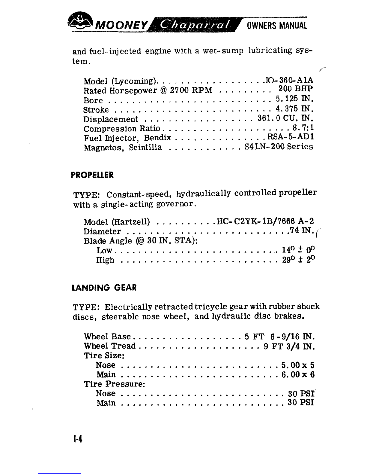
and fuel- injected engine with a wet- sump lubricating sys-
tem.
Model (Lycoming).
.IO-
36GAlA
<-
................
Rated Horsepower
@
2700
RPM
.........
200
BHP
...........................
Bore 5.125
IN.
..........................
Stroke
4.375
IN.
..................
Displacement 361.0 CU,
IN.
.....................
Compression Ratio
8.7:
1
...............
Fuel Injector, Bendix RSA- 5-AD1
............
Magnetos, Scintilla
S4W-
200 Series
PROPELLER
TYPE: Constant- speed, hydraulically controlled propeller
with
a
single-acting governor.
..........
Model (Hartzell)
HC-
C2Y
K-
'lB/7666
A-
2
..........................
Diameter
.74
IN.
j
Blade Angle
(@I
30
IN.
STA):
...........................
Low.
14O
2
00
High
..........................
2g0
f
20
LANDING GEAR
TYPE: Electricallyretractedtricycle gearwithrubber shock
discs, steerable nose wheel, and hydraulic disc brakes.
Wheel Base.
.................
5
FT
6
-
9/16
IN.
Wheel Tread
....................
9 FT
3/4
IN.
Tire Size:
Nose
.........................
.5.00
x
5
Main
.........................
.6.00
x
6
Tire Pressure:
Nose
...........................
30
PSE
Main
...........................
30
PSI
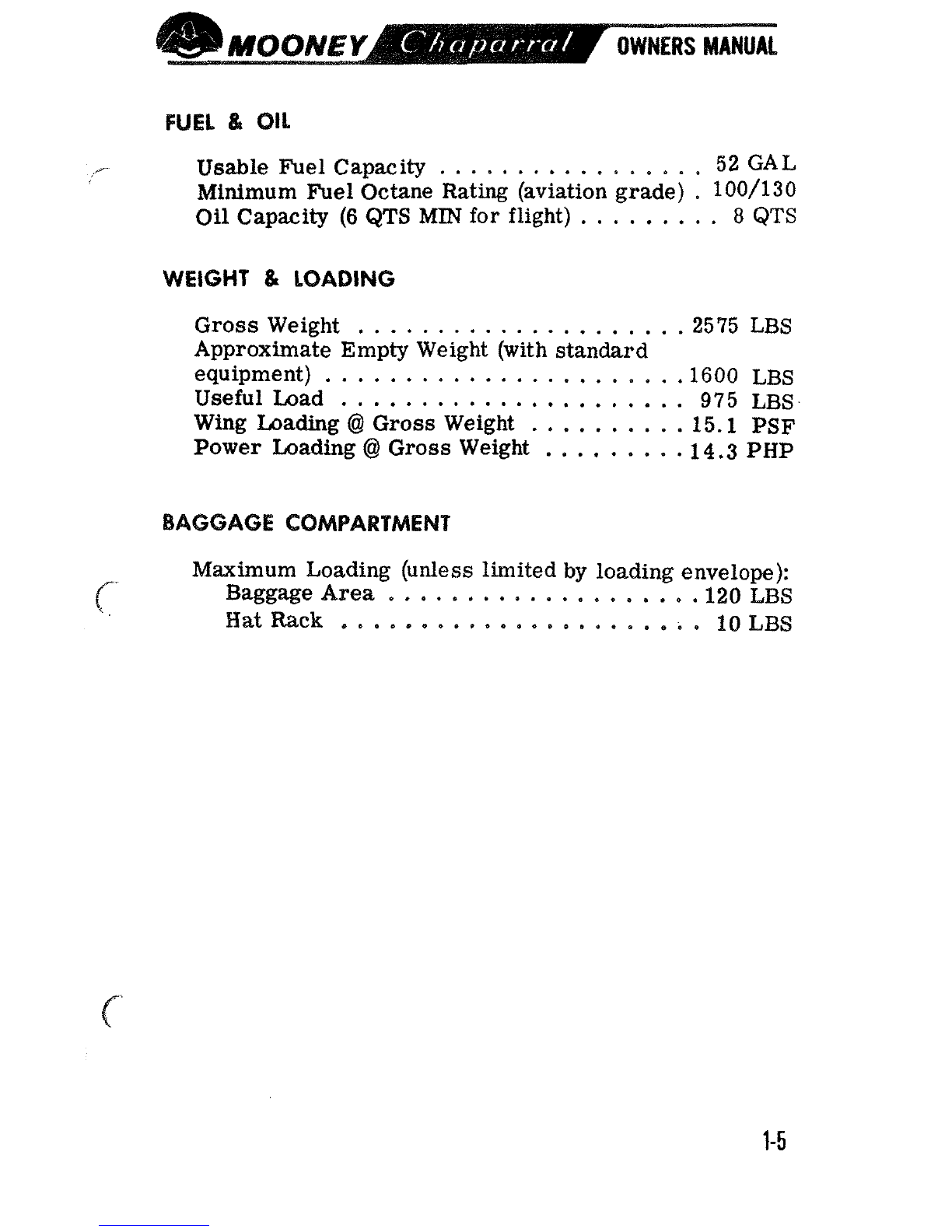
FUEL
&
811
.-.-
Usable Fuel Capacity
.................
52
GAL
Minimum Fuel Octane Rating (aviation grade)
.
100/13
0
Oil Capacity
(6
QTS
MIN
for flight)
.........
8
QTS
WEIGHT
&
LOADING
Gross Weight
.....................
2575 LBS
Approximate Empty Weight (with standard
equipment)
......................
.I600
LBS
.
Useful Load
......................
975 LBS
Wing Loading
@
Gross Weight
..........
15.1
PSF
Power Loading
@
Gross Weight
.........
14.3
PHP
BAGGAGE
COMPARTMENT
Maximum Loading (unless limited
by
loading envelope):
Baggage Area
...................
.I20
LBS
Hat
Rack
.......................
10
LBS
@MOOMY-
000
OWNERS
MANUAL
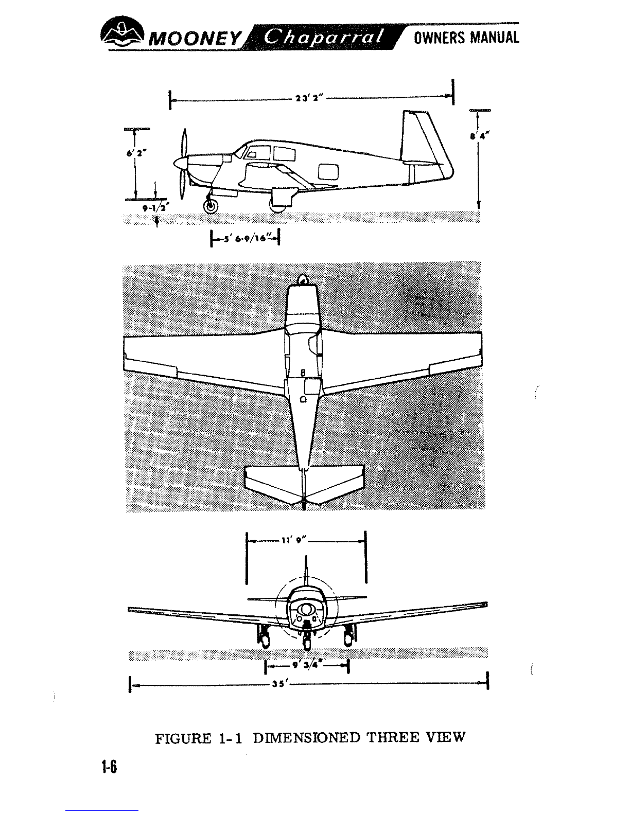
FIGURE
1-
1
DIMENSIONED
THREE
VIEW
1-6
SECTION
POWER PLANT
a
ENGINE CONTROLS
....................
2-4
IGNITION SYSTEM
.....................
2-5
.......................
FUEL SYSTEM
2-6
OIL SYSTEM
.........................
2-6
ENGINE COOLING
.....................
2-7
.....................
VACUUM SYSTEM
2-7
INSTRUMENTS
FLIGHT INSTRUMENTS
.................
2-7
FLIGHT
CONTROLS
............
PRIMARY FLIGHT CONTROLS
2-8
BOSITrVE CONTROL
...................
2-9
.....................
TRIM CONTROLS
2-10
.................
WING FLAP CONTROLS
2-10
UNDING
GEAR
ELECTRIC GEAR RETRACTION SYSTEM
.....
2-11
EMERGENCY GEAR EXTENSION SYSTEM
.....
2-12
BRAKE
&
STEERING SYSTEMS
............
2-12
ELECTRICAL POWER
ALTERNATOR
&
BATTERY
...............
2-12
CIRCUIT
BREAKERS
...................
2-13
ANNUNCIATOR LIGHTS
.................
2-15
INSTRUMENT
&
PLACARD LIGHTS
.........
2-16
CABIN LIGHTING
.....................
2-16
CABIN ENVIRONMENT
HEATDAG
&
VENTILATING SYSTEM3
........
2-16
WINDSHIE
W
DEFROSTING SYSTEM
........
2-17
CABIN
SEATS
&
SAFETY BELTS
................
2-18
BAGGAGE
&
CARGO AREAS
..............
2-18
dB
-
MOONEY-
#
00
OWNERS
MANUAL
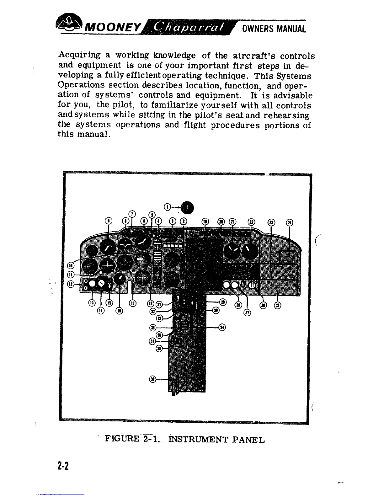
Acquiring a working knowledge of the aircraft's controls
and equipment is one of your important first steps
in
de-
veloping a fullyefficientoperating technique. This Systems
Operations section describes location, function, and oper-
ation of systems' controls
and
equipment. It
is
advisable
foryou, the pilot, to familiarize yourself with
all
controls
and
systems while sitting in the pilot's seat
and
rehearsing
the systems operations
and
flight procedures portions of
this manual.
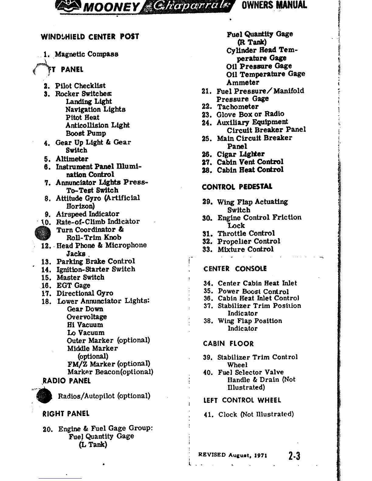
2.
PUot Checklbt
3.
Rocker
Switcbea
Landtng Light
Navigation Lights
Pitot Heat
Anticollision
Light
Wst
Pump
4.
Gear
Up
Light
t
Gear
Mteh
5.
Altimeter
6.
Inetntment
Panel
Illumi-
nation
Control
7.
Annunciator
Lights
Press-
To-Test
Switch
8.
Attitude
Gyro
(Artificial
Borfion]
9.
Airspeed
Indicator
10. W-of-Climb Indicator
Turn Coordinator
&
a
Roll-Trim
Knob
12.
Head Phone
&
Microphone
Jacks.
13.
Parking
Brake
Control
'
14.
Ignition-Starter Sroitch
15.
Master Switch
16.
EGT
Gage
17.
Directional
Gyro
18.
Lower
Annunciator
Lights:
Gear
Down
Overvoltage
Hi
Vacuum
I.&
Vacuum
Outer Marker (optional)
Middle Marker
(optional)
FM/Z
Marker (optional)
Marker
Beacon(optional)
.RADIO PANEL
-6
mdios/iiutopilot (optional)
RIGHT
PANEL
20.
Engine
6.
fie1Gage Group:
Fuel
Quantity Gage
(L
T&)
Aael
Quaatttp
Gage
(R
Task)
Cylinder
&sad
Tem-
pe-n,
Onee
Oil
Pmssrt~e
Gage
011Ternperatare
Gage
Ammeter
21.
Fuel Pressure/Bdantfold
Pressure
Gage
22.
Tachometer
23.
Glove
Box
or Radio
24.
Auxiliary
Eqrripmed
circuit Breaker Panel
25.
Main
Circuit Breaker
Palael
20.
Cigar
Lightsr
27.
Cabin
Vent
Control
28. Cabin
Reat
Coadrol
CONTROL
P€DES"IAL
2s.
Wing
Flap Actuating
Switch
30.
Engine
Control Friction
Lock
31.
Throttle Control
32.
Propeller Control
33.
Mixture
Control
CENTER
CONSOLE
34.
Center Cabin
Heat
Inlet
35.
Power
&lost
Control
36.
Cabin
Heat
Inlet Control
37. Stabilizer
Trim
Position
Indicator
38.
Wing
Flap Position
Indicator
CABIN
FLOOR
39. Stabilizer
Trim
Control
Wheel
40.
Fuel
Selector Valve
Handle
&
Drain (Not
Illustrated)
LEFT CONTROL WHEEL
41.
Clock (Not Illustrated)
REVISED
August,
1971
2.3
L.

POWER
PUNT
('1
C,
ENGINE
CONTROLS
The engine control levers are centrally located, between
the pilot and co-pilot, on the engine control pedestal. The
throttle lever, withitsround
knob,
regulates manifoldpres-
sure. Pushing the lever forward increases
the
setting;
pulling the lever aft decreases the setting.
The propeller control lever, with its crowned
knob,
con-
trols engine
RPM
through the propeller governor. Push-
ing
the lever forward increases engine
RPM;
pulling
the
lever
aft
decreases
RPM.
The mixture control lever, with its red hexagon
knob,
es-
tablishes the fuel-air ratio (mfxture). Pushing the lever
full
forward sets themixture
to
full-rich, pulling the lever
aft leans
the
mixture,
and
pulling the lever
to
its
maximum
aft
travel position closes the idle cutoff valve, shutting
down
the engine. Precise mixture settings
are
established
by
observing the
EGT
gage
on the pilot's instrument panel
while aqjusting the mixture
control lever.
A
large friction-lock knob
on the right side of the en-
gine
control pedestal holds
the controls in the desired
setting
and
preventscontrol
creeping during flight.
The
powerboost
air
control
lever, mounted in
the
cen-
ter consoleto the left of the
..
,
engine control pedestal
allows the selection of
fil-
FIGURE
2-2.
ENGINE
tered induction
air
or un-
mUCTION
SYSTEM
filtered directram
air.
An

annunciator light on
the
instrument panel illuminates when
the power boostair control lever
is
set for ram air and
the
0
landing
gear
is
down. When operating
at
full throttle, us-
ing ramair will increase the manifold pressure
by
allowing
engine induction
air
to
bypass the induction air
filter.
The
use of ram air must
be
limited to clean, dust-free
air
at
altitude. The engine
will
operate on direct unfiltered air
when the power boost
air
control lever
is
down. The an-
nunciator light reminds the pilot to push the engine induc-
tion
air
control leverupward forfiltered
air
before landing.
Should
the
induction
air
filter
clog,
a
spring-loaded door
in the induction system
will
open
by
induction vacuum to
allow alternate
air
to
enter
the
engine.
A11
engine
instruments
except
the
EGT
gage
are
grouped
in
the rightinstrumentpanel. Colorarcson instrument faces
markoperating ranges. Properinterpretation of engine in-
strument readings
is
essential for selecting optimum con-
trolsettings
and
for maintaining maximum cruise fuel
eco-
nomy. Engine limitations
are
given
in
Section
V.
IGNITION SYSTEM
The
left
magneto has a setof fixed
retard
breaker points
thataid
in
smoother, easier starting.
A
battery-powered
starting vibrator supplies a long-duration, boosted spark.
The starter-ignition switch, mounted on the left of the in-
strument panel, combines both ignition and starting func-
tions. Turning the ignition key clockwise through
R,
L,
and BOTH to the START
MAG
position and then pushing
forwardonthe key and receptacleengages the
starter.
Re-
leasing the key when the engine starts allows the switch
to
return by spring action
to
the
BOTH
position. For safety,
the starter-ignition switch must
be
left at OFF when the
engine
is
not running.
FUEL
SYSTEM
Two integral sealed sections
carry
the fuel in the forward
C'
inboardarea of the wings. Full fuelcapacity
is
52
gallons.
There are sump drains at the lowest point in each
tank
for
takingfuelsamples
to
check forsedimentcontamination and
condensed water accumulation. Section
VII
discusses the
fuel sampling procedure.
An illuminated three-position
fuel
selector handle on the
cabinfloor setsthe selector valve below the floorboard for
LEFT
tank,
RIGHT
tank,
or the
OFF
position. The fuel
selector valve assembly contains
a
valve for draining con-
densedwater andsediment fromthe lowest
point
in
the fuel
linesbeforethe first flightof the
day
and
after
each refuel-
ing. Section
VII
discussesthe selector valve flushing pro-
cedure.
Fuel feedsfrom onetank ata time
to
the selector valve and
through the electricfuelpump enroute
to
the engine-driven
pump
and
the fuel injector unit. Electric fuel-level trans-
@
mitters inthetanks operatefuel gages inthe enginecluster.
The master switchactsatesthe fuelquantity indicator sys-
tem
to
maintain anindication of fuelremaining
in
each
tank.
The fuel pressure
gage
registers fuel pressure
in
the line
to
the injector. Vents in each fuel
tank
allow for overflow
and ventilation.
OIL
SYSTEM
The engine
has
a full-pressure wet-sump oil system with
an
8
quart capacity. The automatic bypass control valve
routes oil flow around the oil cooler when operating
tem-
peratures
are
below norm& or when the cooling radiator
is
blocked.
The enkine oil should be kept at
6
to
8
quarts. Lycorning
a
ServiceInstruction
1014
(latest revision)givesrecommended
oil specifications and oil change intervals.
0
The
down-draft
engine cooling system provides ground and
inflight power plantcooling.
Engine
bafflingdirects
air
over
and around the cylinders and out the cowl flap openings.
Cowl flap
doors
allow
proper
air
flow on the ground
and
during
low-speed high-power climb. Pulling the cowl
flap
control below the instrument panel,
to
the
left
of the engine
control pedestal, opens
the
cowl flaps.
VACUUM
SYSTGM
Anengine- drivenvacuum pump
supplies
suction
br
t&
vac-
uum-operated gyroscopic
flight
instrumente
and
the
Mboney
Positive
Control
sy@em.
Air
entering
the
vamum-powered
instruments
is
filtered; hence,
sluggish
or
erratic
opera-
tion
of
vacuum- driven
Instruments
may
indieate
that
a
clog-
ged vacuum filter element
is
preventing
ackquate
airin-
a
take.
The
HI
or
LO
vacuum annunciator
light
will
ilhuni-
nate
if
vacuum
is
above or
below
limits.
FLIGHT
INSTRUMENTS
The basic flight instruments
are
grouped on the shock-
mounted
flight
panel directly in front of the pilot's
seat.
Instrument arrangement
is
in the standard T-grouping
with
the attitude
gyro
at
top
center
and
the directional
gyro
im-
mediately below. The airspeed indicator and the altimeter
cross
the
"T".
The
vertical speed indicator
and
the
turn
coordinator atleft
of
the directionalgyrocomplete thestand-
ard flight instrumentation.
A
standard eight-day clock
is
mounted
in
the pilot's control
wheel. Themagnetic compass
is
mountedonthe windshield
post above the instrument panel. The outside air temper-
ature gage
is
installed in the windshield.

~MOONEV-
0#0
OWNERS
MANUAL
There
is
spaceand ltghtingfor fouropttonal radio tndtcrttore
on the flight panel.
A
back-lighted flight checklist
is
on the
C)
extreme right of the flight panel.
Space
for
an
optional re-
mote indicating compass
is
at the top left of the panel. The
optional marker beacon indicator lights mount between the
radio indicators at right center
below
the annunciator ltght
group.
A pitot
tube,
mounted on the lower surface of the left
wing,
picks up airspeed indicator ram air.
A
heated pitot pre-
vents pitot
tube
icing when flying
in
moisture-laden
air.
A drain valve
is
located on the forward bottom skin of
the left
wing
just outboard of the
wing
fillet. Static portson
each side of the
tail
cone supply static air pressure for
the
altimeter, the
air
speed indicator,
and
the vertical speed
indicator.
A
drain valve
is
located on
the
fuselage bottom
skin below the tail cone access door. An optional alternate
staticpressure source valve may be installed behind the
vertical speed indicator.
0
A
stall warning horn, mounted in the cabin head
liner
and
triggered
by
a
sensing vane on the left wing leading edge,
will sound when airspeed drops to near
stall
speed.
The
sound becomes steady astheaircraftapproaches
a
complete
stall.
A
landing gear position light in theannunciator panel shows
amberwhen the gear
is
retracted.
A
green annunciatorlight
illuminates when the gear
is
down-and-locked. Retarding
the throttle settingbelow
12
inches manifold pressure when
the gear
is
not in the down-and-locked position causes the
gear warning horn in the cabin headliner
to
sound with
a
regular, intermittent tone.
FLIGHT
CONTROLS
PRIMARY FLIGHT CONTROLS
7
,
Push-pull tubes withself-aligning rodend bearings actuate
the primaryflight controlsurfaces. Beveled aileron
trail-
ing edgeshelp reduce pilot controlforces requiredforflight
maneuvering. A spring-
loaded interconnect device
Cb
indirectly joins the aileron
and rudder control systems
to assist
in
lateral stability
during flight maneuvers.
Control surface gap
seals
minimize airflow through
the hinge slots and reduce
drag.
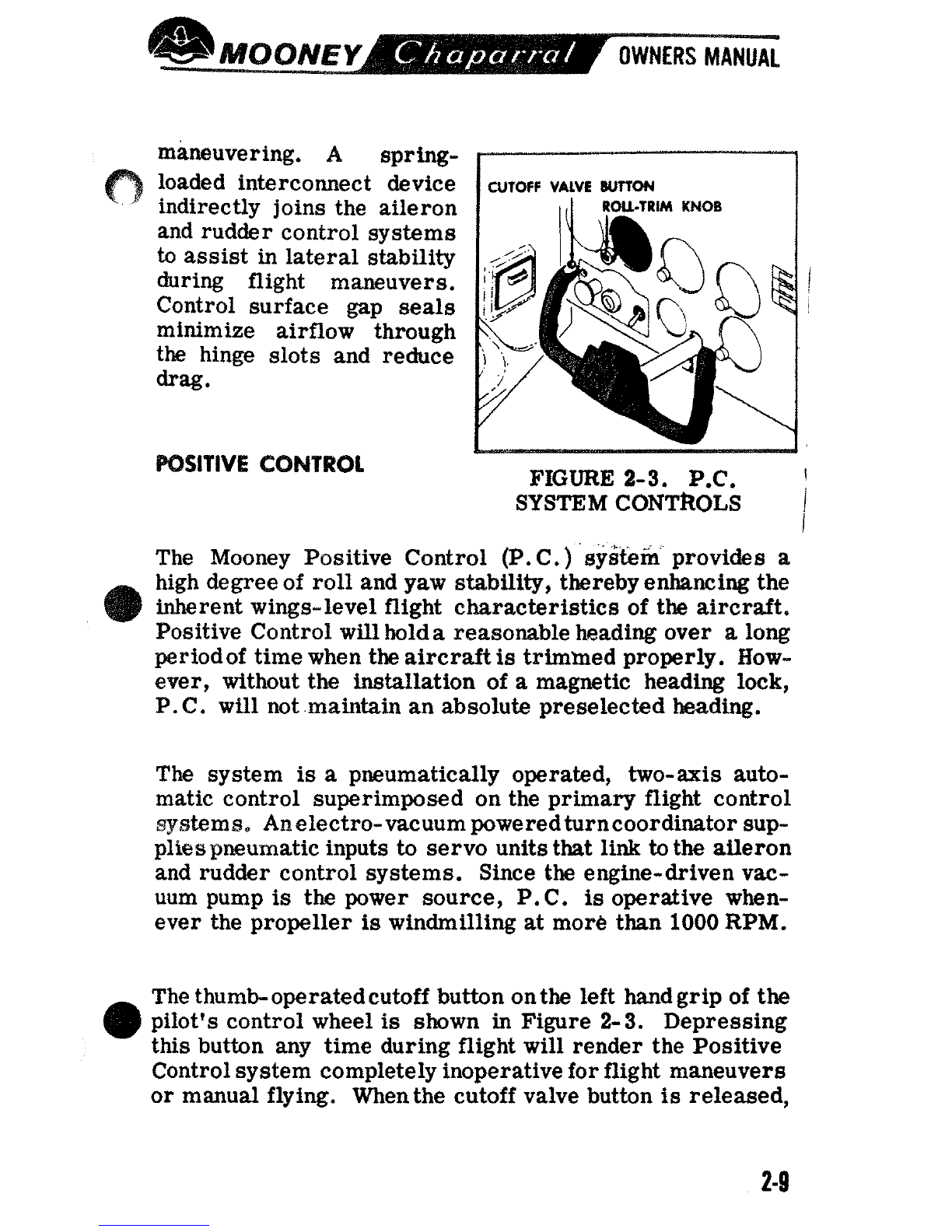
POSITIVE
CONTROL
CUTOFF
VALVE
WON
,
ROU-TRIM
KNOB
FIGURE
2-3.
P.C.
1
SYSTEM CONTROLS
1
i
The Mooney Positive Control (P.C.) systeib provides
a
high degreeof roll and yaw stability, thereby enhancing the
inherent wings-level flight characteristics of
the
aircraft.
Positive Control willblda reasonable heading over
a
long
periodof timewhen the aircraft
is
trimmed properly. How-
ever, without the installation of a magnetic heading lock,
P
.
C
.
will not maintain an absolute preselected heading.
The system
is
a
pneumatically operated, two-axis auto-
matic control superimposed on the primary flight control
systems, An electro-vacuum poweredturncoordinator sup-
plieapneurnatic inputs to servo unitsthat link
to
the aileron
and rudder control systems. Since the engine-driven vac-
uum pump
is
the power source,
P.
C.
is
operative when-
ever the propeller
is
windmilling at more than
1000
RPM.
Thethumb-operatedcutoff button on
the
left handgrip of
the
pilot's control wheel
is
shown
in
Figure
2-3.
Depressing
this button any time during flight will render the Positive
Control system completely inoperativeforflight maneuvers
or manual flying. Whenthe cutoff valve button
is
released,
the aircraft will return unassisted
to
was-level flight.
P.C. can be manually overriden with little effortif the sys-
tem should malfunction. Manually over-powering the sys-
<'
tem will not damage the aircraft or the P.C. components.
The roll-trim knob on the turn coordinator, as shown in
Figure
2-
3,
provides an aileron trim function throughthe
P.C. system. Rotating the knob trims the aircraft about
its
roll axis to compensatefor asymmetrical fueland
pas-
senger loadings.
The P.
C.
system
is
installed
to
help alleviate pilot fatigue.
But like any other system in the aircraft, P.C. must
be
monitored for proper functioning.
TRIM CONfROLS
For pitch trim control, the entire empennage pivots on the
tail
cone attachmentpoints to increaseordecrease the hori-
c:
zontal stabilizer angle. This design allows flight trim
es-
tablishment with minimum control surface deflection. A
pointer in
a
slot located on the center console indicates
stabilizertrim position. Forward rotationof the trimwheel
lowersthe nose; rearward rotationraises the nose in flight.
WING
FLAP
CONTROLS
The flap switch on the right of the engine control pedestal
operates the electrically-actuated wide- span wing flaps.
Holdingthespring-loaded switch in the down positionlowers
the flaps to the desired angleof deflection. A pointer in the
center console indicates flap position. The intermediate
mark in the pointer range
is
the flap TAKEOFF setting.
(
Holding the switch in the
UP
position, retracts
the
flaps.
-
Simply releasing the spring-loaded switch to return to the
OFF
positionstops the flaps at
an
intermediatepositiondur-
ing either extension or retraction.

LANDING
CEAR
ELECTRIC
GEAR
RETRACTION
SYSTEM
The two-position electric
par
control switch, identified by
its wheel-shaped
knob,
is
located
to
the right of the altim-
eter between the annunciator light panels.
There are three ways to see that the electrically-actuated
gear
is
down-
and- locked:
(1)
The
green gear-down annunciator light illvminates
.
(2) The indicator marks
align
as
seen
on
that.
floorboard
visual gear-position indicator.
(3)
The gear warning
horn
does
mt
sound
at
approach
power setting
of
below
12
inches manifold pressure.
f
Position annunciatorlights and a warning horn provide
vis-
ual and audible gear position signals. An amber
signal
light
(marked
GEAR
UP)
will
show continuously when the
gear
is
fully retracted. A green signal light (marked
CEAR
DN)
shows continuously when
the
gear
is
fully extended. Both
lights are out
as
the
gear changes position.
Theilluminatedgear- down position indicator
in
the
floor-
board aftof the centerconsole
has
two
marksthat alignwhen
the gear
is
down.
Retarding
the
throttle below 12 inches
manifold pressure causes the gear warning horn to emit
a
regular, intermittent tone unless the gear
is
down-and-
locked.
An
airspeed-actuated safety switch in the pitot system or
a
mechanically actuated "Sq~quat-Switch"in
the
retraction
C
system prevents landing gear retraction until attaining
a
safe takeoff airspeed. The safety switch
is
not designed
to
substitute for the gear switch in keeping
the
gear
extend-
'
ed while taxiing,
taking
off, or landing.
i
-


