manuals.online logo
Brands
  1. Home
  2. •
  3. Brands
  4. •
  5. Wowings
  6. •
  7. Aircraft
  8. •
  9. Wowings Duck Instructions for use

Wowings Duck Instructions for use

Other Wowings Aircraft manuals

Wowings Booby Instructions for use

Wowings

Wowings Booby Instructions for use

Wowings Skua 1500 Instructions for use

Wowings

Wowings Skua 1500 Instructions for use

Popular Aircraft manuals by other brands

Skywalk Mescal 4 instruction manual

Skywalk

Skywalk Mescal 4 instruction manual

Cessna U206G STATIONAIR Pilot operating handbook

Cessna

Cessna U206G STATIONAIR Pilot operating handbook

Cirrus SR22 Maintenance manual

Cirrus

Cirrus SR22 Maintenance manual

Schleicher ASK 21 Assembly & Disassembly

Schleicher

Schleicher ASK 21 Assembly & Disassembly

Cirrus SR20 Maintenance manual

Cirrus

Cirrus SR20 Maintenance manual

Skywalk Tequila 2 Manual/service

Skywalk

Skywalk Tequila 2 Manual/service

MAULE M-7-235B Airplane Flight Manual

MAULE

MAULE M-7-235B Airplane Flight Manual

Tecnam P92 Echo Super Maintenance manual

Tecnam

Tecnam P92 Echo Super Maintenance manual

Wills Wing HP II Owner's and service manual

Wills Wing

Wills Wing HP II Owner's and service manual

MAULE MX-7-180B Airplane Flight Manual

MAULE

MAULE MX-7-180B Airplane Flight Manual

Ozone ZENO 2 Pilot's manual

Ozone

Ozone ZENO 2 Pilot's manual

Boeing 737 Quick reference handbook

Boeing

Boeing 737 Quick reference handbook

MHD MHDFLY TINY GLIDER Z5630 Manual and using instructions

MHD

MHD MHDFLY TINY GLIDER Z5630 Manual and using instructions

Ozone Roadster Pilot's manual

Ozone

Ozone Roadster Pilot's manual

SpeedWing Mini SpeedWing EX Assembly instructions

SpeedWing

SpeedWing Mini SpeedWing EX Assembly instructions

Daher-Socata TBM 900 Pilot's information manual

Daher-Socata

Daher-Socata TBM 900 Pilot's information manual

Aircraft REIMS F152 Flight manual

Aircraft

Aircraft REIMS F152 Flight manual

Cessna 172 Skyhawk SERIES owner's manual

Cessna

Cessna 172 Skyhawk SERIES owner's manual

manuals.online logo
manuals.online logoBrands
  • About & Mission
  • Contact us
  • Privacy Policy
  • Terms and Conditions

Copyright 2025 Manuals.Online. All Rights Reserved.

- 1 -
Wowings Duck
CONSTRUCTION MANUAL
Copyright 2006 Wowings
www.wowings.com
- 2 -
Thanks very much for purchasing the Duck combat wing. Although made primarily of soft EPP
foam, this RC slope glider is still capable of causing significant damage to property and serious
personal injury or death to bystanders or yourself. Please ensure that you fly this model in a safe
and responsible manner and obey your local laws and regulations. By building and/or flying the
Duck you assume all responsibility for any damage or injury it may cause. Wowings accepts no
liability for any damage or injury resulting from the use of our products. If you do not agree to these
terms, please contact your place of purchase prior to commencing construction to arrange returning
this kit for a refund.
Please do NOT copy any aspect of the Duck’s design, including its proprietary airfoil sections, even
if only for private use. We have invested a lot of time in developing this unique flying wing and it is
based on a foundation of many years of flying and building experience. These kits are not mass-
produced by a large faceless corporation. We directly rely on, and sincerely appreciate, your
support through the purchase of our glider kits.
Now onto the fun stuff…First, please ensure that nothing is missing from the Duck kit and that
none of the contents have been damaged. If anything is missing or damaged please contact your
place of purchase immediately to make arrangements for replacement parts to be supplied. Your
Duck kit should contain the following:
•2 x EPP foam wing halves
•3 x lengths carbon ribbon spar (two short and one long)
•2 x lengths of balsa (marked with angled lines for fixed trailing edge pieces)
•2 x steel pushrods with clevises attached
•1 x piece of coreflute marked with outlines for fins
•1 x pack of Dubro nylon control horns (total of 2 control horns)
•1 x pack of Dubro E-Z connectors (total of 2 connectors)
. This construction manual!
To complete the kit you will require the following tools and supplies:
•Sharp trimming knife (large retractable disposable type is ideal)
•Sandpaper and sanding block, screwdriver, drill, pliers and ruler
•48mm (2”) wide cross-weave filament tape
•Covering material (eg. coloured packing tape or iron-on film such as UltraCote or Profilm)
•3M “Super 77” or 3M “Multi-Purpose” spray adhesive
•5 minute epoxy glue (eg. Selley’s Araldite)
•CA glue (eg. Pacer’s ZAP CA) or Polyurethane glue (eg. Selley’s Durabond, Gorilla Glue or
Elmer’s ProBond)
•Hot-melt glue –not essential
•Lead for nose weight
The following radio equipment is recommended:
•Rechargeable receiver battery pack in flat configuration of 4 x AA size cells.
•Receiver
•2 x standard size servos (eg. Hitec HS-311).
- 3 -
Take a few minutes to have a quick read through this entire instruction manual prior to starting so
that you have a basic overview of the steps involved. Please don’t be tempted to deviate from these
instructions unless you are an experienced builder and are confident that your changes won’t
negatively affect the structural integrity or flying performance of the Duck. These instructions are
based in metric units but I have also tried to include the equivalent imperial measurement as much
as possible. For your reference, 1 inch (”) equals 25.4 millimeters (mm). An online version of these
instructions, with colour photos, is located on Wowings website at:
www.wowings.com/instructions/duck.doc
INITIAL WING ASSEMBLY
1. Remove the two wing halves from their beds and glue the wing together using hot-melt
glue, contact adhesive or spray adhesive (epoxy is not ideal because it’s hard and brittle).
2. Locate the two balsa trailing edge pieces. Cut along the angled lines marked using a sharp
blade (many light cutting strokes are better than trying to cut through in one or two goes).
The remainder will be used later for the “elevons” (moveable control surfaces for combined
elevator and aileron function). Place the balsa trailing edge pieces up against the foam sub-
trailing edges (rear edge of the EPP foam wing cores) in the middle of the wing to make sure
that their angled centre joint fits nicely together. The BOTTOM surface of the balsa trailing
edges is the one that had the cut-out lines marked on them (and the surface that meets its
leading edge at a 90 degree angle). When butted up against the foam sub-trailing edge, the
bottom surface of the balsa trailing edge piece should form a straight line continuation of the
foam airfoil shape.
3. Once you are happy that they will fit
nicely, round off the top and bottom edges
of the outer end only of each balsa trailing
edge piece (not where they join together in
the middle) to make covering easier later.
4. Use 5 minute epoxy to glue one of the
balsa trailing edge pieces to the foam. Use
a straight edge (ruler) held against the rear
section of the bottom surface of the wing
and the bottom of the balsa trailing edge to
ensure correct alignment (straight line).
Once the glue has cured repeat this process
for the second balsa trailing edge piece,
also end gluing to the first piece where
they meet at the center of the wing.
5. Measure approximately 25mm (1”) in from
each wingtip along the foam sub-trailing
edge. This will be the width of your
trailing edge fin supports made from small
sections of the two remaining lengths of
balsa trailing edge.
6. Hold one of the lengths of balsa trailing
edge up against the foam sub-trailing edge
at a wingtip so that its end is aligned with
the line you just marked (25mm in from
- 4 -
the tip). Use a straight edge (ruler) held against the wingtip to mark the correct width
(25mm) and correct angle onto the balsa trailing edge and then cut along this line.
7. Repeat for the second wingtip using the other length of balsa trailing edge. Keep both
remaining pieces for the elevons.
8. The leading edge face of each of these
balsa fin support pieces needs to be shaved
or sanded slightly so that it meets its top
and bottom surface at the same angle ie. so
its cross-section forms an isosceles triangle
9. Round off the top and bottom edges of the
inner end only of each balsa trailing edge
fin support piece (not at the wingtip).
10. Use 5 minute epoxy to glue on the two
balsa trailing edge fin support pieces. They
should be attached so that they form a
reflexed (trailing edge raised) airfoil shape
at the tips. The trailing edge should be raised about 2mm or 3mm above a straight edge
(ruler) held on the underside of the airfoil.
11. The remaining two lengths of balsa trailing edge will now be used to form the two elevons.
Hold one of the pieces so that it is firmly up against the foam sub-trailing edge with its
angled end up against the outer end of the fixed trailing edge piece. They should match up
perfectly ie. the cuts should be parallel. Now slide it away slightly so that there’s a gap of
about 2mm (3/32”) between it and the fixed trailing edge, with its other end underneath the
trailing edge fin support. Mark a line on the elevon piece that is parallel to the fin support
with a 2mm gap ie. the elevon should have a 2mm gap at each end. Now cut out the elevon
along the angled line you just marked.
12. Repeat for the second elevon on the other
wing half.
13. Using a sanding block with rough
sandpaper (or a balsa plane), sand/plane a
45 degree bevel along the leading edge of
each elevon, with the 45 degree opening on
their bottom surface (ie. they’ll be hinged
on the top surface).
- 5 -
14. Round off the top and bottom edges of each end of both elevons. Put them aside to be
attached later.
RADIO AND SPAR INSTALLATION
15. Gather together all the radio equipment you plan to install into the glider and test that it is
working properly. Ensure that your receiver and transmitter batteries are fully charged.
16. Working on the BOTTOM surface of the wing, measure back about 230mm (9”) from the
tip of the nose. At this point draw a line perpendicular (at right angles) to the wing’s central
join line that extends 305mm (12”) to either side ie. forming a straight line measuring
610mm (24”) centered over the wing’s join line. This marks the location for one of the small
(24”) carbon ribbon spars.
17. Cut a 10mm (3/8”) deep slit along this spar
line and trial fit the carbon ribbon spar.
18. Once you’re happy with the fit, glue the
spar in place using thin CA glue. Dribble
the glue along the top of the spar while it’s
in position. Although the glue bonds
within a couple of seconds when exposed
to air, some of the glue will penetrate into
the foam and can take a couple of hours to
completely cure. CA “kicker” will ensure
it sets rapidly; otherwise you’ll just need to
be patient. Alternatively you can use
polyurethane (PU) glue for gluing the spars in. Please seek advice if you have not used PU
glue previously as it foams and expands while curing and can create a mess of your wing.
19. The following steps now reference the TOP surface of the wing.
20. Draw a line parallel to the leading edge (front edge) of the wing setback 35mm, or 1 3/8”,
(measured perpendicular to the leading edge) extending from the nose to about 1/3 span of
each wing half. In consideration of safety and durability, nothing should be installed or
embedded in front of this line. NB: If you wish to use your Duck in combat competitions
please consult your local rules for the minimum leading edge and nose setback requirements
to ensure this distance complies. Usually it will be a minimum of 1 1/2” (38mm) back from
the leading edge measured chord-wise (line of flight).
21. Centre your receiver’s flat 4xAA size
battery pack on top of the wing about
65mm (2 9/16”) back from the tip of the
nose. Trace around it with a pen.
22. Position your receiver directly behind the
battery pack leaving a 25mm to 35mm (1”
to 1 3/8”) buffer of foam between them.
Trace around it with a pen.
23. Draw two lines 175mm (6 7/8”) either side
of, and parallel to, the wing’s centre join
line. These represent the location of the
pushrods for the elevons.
- 6 -
24. Position one of your servos so that its
control arm is aligned with the line you
just marked and one of its mounting lugs is
touching the line setback from the leading
edge ie. it should be as far forward as
possible and orientated so that the servo
arm moves directly forwards and
backwards (line of flight). Trace around
the servo body with a pen.
25. Repeat for the other servo on the other half
of the wing.
26. Measure back 50mm (2”) from the leading
edge of one of the wingtips and 5mm
(3/16”) back from the corner of the servo
case and draw a straight line between
them. Repeat for the other half of the wing.
Now draw a gently curving line joining
these two straight lines that sweeps slightly
forward and curves around passing
inbetween the battery pack and receiver
locations. This line marks the location of
the longer (48”) carbon ribbon spar.
27. Cut a 10mm (3/8”) deep slit along this spar
line commencing approximately 50mm
(2”) inwards from each wingtip. Trial fit
the carbon ribbon spar to ensure the slit is
deep enough. The spar should sit about 2mm or 3mm (1/8”) below the top surface of the
wing towards the centre to allow radio leads to pass over.
28. Once you’re happy with the fit, glue the spar in place as per the first one.
29. The remaining small (24”) carbon ribbon spar is used to reinforce the area either side of the
gap between the fixed trailing edge and the elevons. Draw two lines extending 305mm (12”)
down each wing half, parallel to the foam sub trailing edges and setback about 20mm (3/4”)
with the lines joining in a curved arc at the centre join of the wing just a little forward of the
balsa trailing edge. Ensure it doesn’t overlap the spar embedded in the bottom surface.
30. Cut a 10mm (3/8”) deep slit along this spar line. Trial fit the spar and then glue it in place as
per previous spars.
31. Now it’s time to embed your radio equipment into the wing.
32. Cut around the outline you made for the
battery pack all the way through the foam
to the other side. Remove this foam plug
and draw a line vertically up its front side
for later reference.
33. Hold the side of your battery pack against
the side of the foam plug so that it is
centered and trace lines to mark out the
thickness of your battery pack. Repeat this
for all four sides and then cut off a bottom
slice (base) and a top slice (lid) along these
outlines. Mark the top of the slices with an
- 7 -
“x” for later reference and discard the remaining piece of the plug.
34. Using hot-melt glue (best), spray adhesive (sprayed into a puddle and then spread on) or 5
minute epoxy (not ideal), glue the base slice back into the bottom of the battery cut-out hole,
creating a base for the battery recess. Use the markings you made to orientate it correctly,
ensuring a perfect fit. Put the foam lid aside for later use.
35. Decide whether you want to mount your receiver flush with the top surface of the wing or
embed it beneath the surface. Base this decision on the layout and size of your receiver and
whether you intend to use a switch or plug the battery plug directly into the receiver. I
personally usually use receivers that have the plug sockets on the top surface (and preferably
the crystal as well) and mount them flush with the top surface of the wing. This means the
servo plugs are then sticking up above the wing’s surface (adding a little drag and ugliness),
but it is then simple and convenient to just
plug in and take out the battery lead to turn
it on and off and gain easy access for
charging.
36. Cut around the outline you made for the
receiver all the way through the foam to
the other side. Remove this foam plug and
draw a line vertically up its front side for
later reference.
37. Hold the side of your receiver against the
side of the foam plug in the desired
position (eg. flush with the top surface)
and trace the line(s). Repeat this for all
four sides and then cut off a bottom slice
along this outline, and a top slice if you’ve
decided to have your receiver embedded
below the surface. Mark the top of the
slice(s) with an “x” for later reference and
discard the remaining piece of the plug.
38. Glue the bottom slice of the foam plug into
the bottom of the receiver cut-out hole
forming a base for the receiver recess. Use
the marks on its front side and top to
orientate it correctly, ensuring a perfect fit.
If you have a top slice, put it aside for later
use as a lid over the receiver.
39. Cut around the outlines you made for the
servos with a sharp knife all the way down
through the foam. Push out the foam plug
and mark with a vertical line up its front
side for later reference.
40. Hold the side of your servo against the side
of the foam plug flush with the top surface
of the wing and trace out a line. Repeat this
for all four sides and then cut off a bottom
slice along this outline. Mark the top of the
slice with an “x” for later reference and
discard the remaining piece of the plug.
- 8 -
41. Glue the bottom slice of the foam plug into the bottom of the servo cut-out hole forming a
base for the servo recess. Use the marks on its front side and top to orientate it correctly,
ensuring a perfect fit.
42. Repeat this process for the second servo recess on the other side of the wing.
43. Mark out the area next to the servo recess required to accommodate the servo arm and its
movement. It will be about 10mm (3/8”) wide by 20mm (3/4”) long. Cut out a triangular
shaped wedge down to the depth of the servo recess’s floor.
44. Repeat for the second servo recess on the other side of the wing.
45. Mark out an area next to the receiver to accommodate the excess length in the battery and
servo leads (and electronic elevon mixer if used). An area approximately 30mm by 40mm (1
3/16” by 1 9/16”) is usually enough. Cut out a foam plug using the same method used for
the battery, receiver and servo recesses and glue back in a 5mm to 10mm (3/16 to 3/8”) slice
to form a base. Keep the remainder of the foam plug for later use.
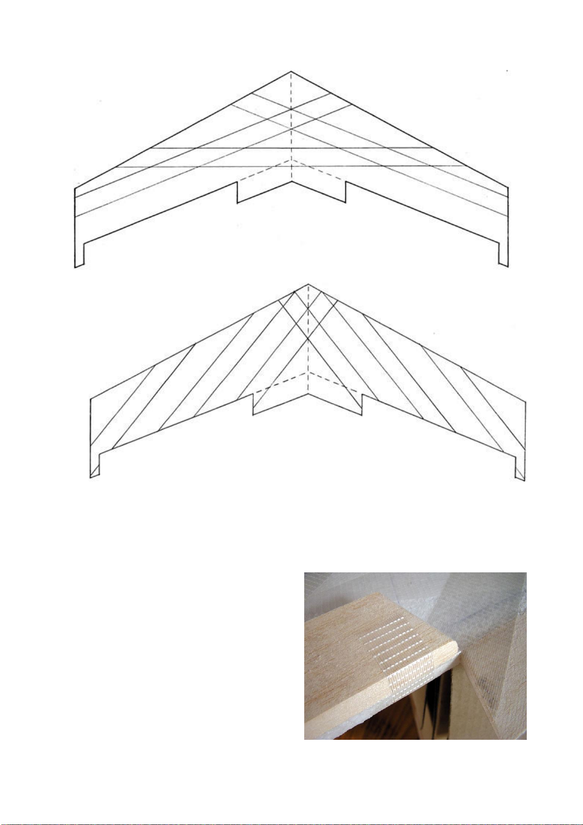
46. Cut slits into the top surface of the wing to accommodate the battery lead and servo leads
inserted on edge. Twist the leads half a rotation where that cross the spar so that they lie flat
over the top of the spar at the crossing point. Avoid cutting into the spar itself.
47. The receiver antenna should be kept clear (and avoid any crossing) of the servo leads,
battery leads and spar if possible in order to avoid possible interference with the radio signal
from the transmitter. If a crossing is required it’s best to orientate it at 90 degrees to
minimise electromagnetic effects.
48. Cut a slit for the receiver antenna that loops around and then runs up about 25mm (1”) in
from the foam sub-trailing edge of one of the wing halves.
49. Fit the battery pack, receiver and servos
into their recesses. Plug everything
together and test that it is working
correctly. Make sure the servo arms are
centered in the correct position when the
transmitter in on and its trims are neutral.
The servo arms should be pointing directly
upwards, or leaning just slightly rearwards.
Unscrew the servo arms and adjust if
required. Also check for correct direction
of servo travel. Viewed from above, when
your transmitter’s elevator stick is pulled
back for “up” control, both servo arms
should move forwards (towards the leading edge of the wing), and both servo arms should
move backwards when “down” control is applied. When your transmitter’s aileron stick is
moved to the right for “right roll” control, the right servo arm should move forwards and the
left servo arm backwards, and opposite when “left roll” control is applied.
50. Perform a “range check” for your radio equipment now. You should be able to control the
servos smoothly from at least 10 to 15 paces away with your transmitter’s aerial retracted
(not extended at all).
51. Once you are satisfied that your radio equipment is functioning correctly it’s time to start
building it into your glider. Soon retrieval of radio equipment will require surgery on your
glider so it is best to make any necessary adjustments or repairs now. Also keep in mind that
you will need to have access to a means of charging your receiver’s battery pack once it is
embedded into the glider. This can be by means of a special switch with charging socket or
as simple as having access to the battery pack’s plug (perhaps just having it plug into an
exposed socket of your receiver).
- 9 -
52. Coil up the excess length in the leads and insert them (along with the electronic elevon
mixer if used) into the recess you made next to the receiver. Slice off an appropriate
thickness from the top of the remains of this foam plug to form a lid and glue it in place
flush with the top surface of the wing.
53. Glue the battery recess’lid in place over the battery pack so it’s flush with the top surface of
the wing.
54. If you chose to embed your receiver below the wing surface, glue in the top slice from your
receiver’s foam plug now so that it is flush with the top surface of the wing.
55. Cut and/or sand off any excess glue from around the foam plugs so that they’re all flush
with the surface of the wing.
TAPING & COVERING
These instructions are based on using 48mm (2”) wide strapping tape with cross-woven fiberglass
filaments (running both length-wise and width-wise), hereto referred to simply as “filament tape”.
The instructions outline the process of covering with 48mm (2”) wide coloured polypropylene tape
due to its simplicity and low cost. Those who wish to spend a little extra money and take a little
extra care can use a variety of other covering materials such as Ultracote, Oracover and Profilm.
These iron-on coverings provide a much nicer finish and a little more strength but are a bit trickier
to apply correctly. If using an iron-on covering be sure not to use too high a heat or it may deform
(melt) the foam. Also be careful not to introduce any warps or twists into the wing when shrinking
the covering. 3M Super 77 (“multi-purpose”) spray adhesive is required regardless of the covering
method used and is hereto referred to simply as “spray adhesive”.
56. Thoroughly remove all dust from the glider and your work area.
57. Use masking tape to mask off any exposed radio equipment that you don’t want to get
sprayed with glue.
58. Go outside and spray the entire bottom surface of the wing with spray adhesive and then
place it upside down on a cardboard box (or anything else to keep it up off your work
surface). Let the spray adhesive dry for about 5 to 10 minutes (or until aggressively tacky).
59. Now it’s time to apply the filament tape. This provides essential tensile strength to the EPP
foam wing and helps to keep the glider rigid during flight. For each piece of tape applied
overhang the wing by 25mm to 50mm (1” to 2”) and wrap around to the opposite surface of
the wing. When a piece ends at the balsa trailing edge you can just cut if off flush with the
edge (don’t wrap around). Rub each piece that is laid down with some fine sandpaper to
remove the release agent from the tape’s backing for better adhesion of subsequent layers of
filament tape, spray adhesive and/or covering. Thoroughly wipe off the dust that is created
each time.
60. Working on the bottom surface of the wing (that you just sprayed), apply filament tape
following the spar locations as per the following illustration.
- 10 -
61. Then apply diagonal strips of filament tape to the wing as per the following illustration.
62. Go outside again and spray the entire top surface of the wing with spray adhesive. Let dry
for about 5 to 10 minutes (or until aggressively tacky).
63. Apply filament tape patches over the servos and receiver (if mounted flush with the top
surface) to hold them securely in place.
64. Working on the top surface of the wing (that you just sprayed), apply filament tape
following the spar locations as per the bottom surface.
65. Apply diagonal strips of filament tape to
the wing as per the bottom surface.
66. Locate the elevons you prepared earlier
and spray their bottom surface with spray
adhesive. Also spray the bottom surface of
the wing’s foam sub-trailing edge. Let dry
for 5 to 10 minutes.
67. Cut a length of filament tape in half
lengthways and cut into twelve 65mm (2
1/2”) long strips.
68. Centre one of the elevons so that there is a
2mm (3/32”) gap between both its ends
and the ends of the fixed balsa trailing