Seagull Models CESSNA TURBOSKYLANE182 User manual

1
ASSEMBLY MANUAL
Code : SEA 376 PNP electric
Type---------------------- PNP electric
Wingspan--------------- 69 in------------------ (174.5 cm)
Overall Length--------- 49.1 in---------------- (124.8 cm)
Wing Arena------------- 612.3 sq.in----------- (39.5 dm²)
Flying Weight---------- 3.3 kg------------------ (7.3 lbs)
Radio-------------------- 5 channels with 6 servos
Motor-------------------- size 70E
ESC 65A/ Lipo 5s-6S 4000mAh-5000mAh
CESSNA TURBO SKYLANE 182 ELECTRIC 69” WINGSPAN PNP Instruction Manual.
2
ank you for choosing the CESSNA TURBO SKYLANE 182 ELECTRIC 69” WING-
SPAN PNP ARTF by SG MODELS. e CESSNA TURBO SKYLANE 182 ELECTRIC 69”
WINGSPAN PNP was designed with the intermediate/advanced sport yer in mind. It is a
semi scale airplane which is easy to y and quick to assemble. e airframe is convention-
ally built using balsa, plywood to make it stronger than the average ARTF, yet the design
allows the aeroplane to be kept light. You will nd that most of the work has been done
for you already. e motor mount has been tted and the hinges are pre-installed. Flying
the CESSNA TURBO SKYLANE 182 ELECTRIC 69” WINGSPAN PNP is simply a joy.
is instruction manual is designed to help you build a great ying aeroplane. Please read
this manual throughly before starting assembly of your CESSNA TURBO SKYLANE 182
ELECTRIC 69” WINGSPAN PNP Use the parts listing below to indentify all parts.
Please be aware that this aeroplane is not a toy and if assembled or used incorrectly it is ca-
pable of causing injury to people or property. WHEN YOU FLY THIS AEROPLANE YOU
ASSUME ALL RISK & REPONSIBILITY.
If you are inexperienced with basic R/C ight we strongly recommend you contact your R/C
supplier and join your local R/C model Flying Club. R/C Model Flying Clubs oer a variety
of training procedures designed to help the new pilot on his way to successful R/C ight.
ey will also be able to advise on any insurance and safety regulations that may apply.
INTRODUCTION
WARNING
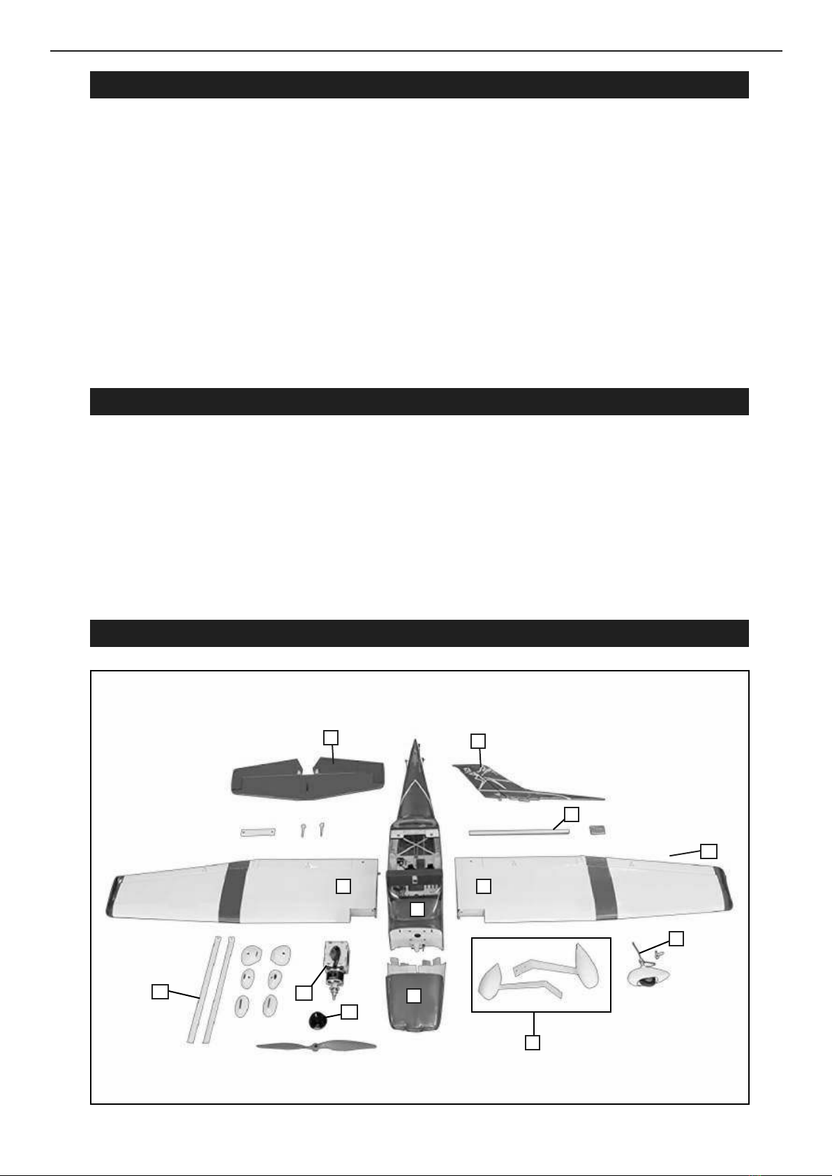
KIT CONTENTS
1
2 2
4
10
33
5
7
9
8
6
10
3
ADDITIONAL ITEMS REQUIRED
TOOLS & SUPPLIES NEEDED
in cyanoacrylate glue.
Medium cyanoacrylate glue.
30 minute epoxy.
5 minute epoxy.
Hand or electric drill.
Assorted drill bits.
Modelling knife.
Straight edge ruler.
2mm ball driver.
Phillips head screwdriver.
220 grit sandpaper.
90° square or builder’s triangle.
Wire cutters.
Masking tape & T-pins.
read-lock.
Paper towels.
KIT CONTENTS RECEIVER INSTALLATION
SEA376 PNP electric
CESSNA TURBO SKYLANE 182
ELECTRIC 69” WINGSPAN PNP
1. Fuselage
2. Wing set (2)
3. Tail set (2)
4. Cowling
5. Wing tube
6. Landing gear
7. Nose Landing gear
8. Ep Motor box
9. Spinner
10. Wing Strut
Make the connections from the rudder and
elevator servos to the receiver. Also connect
the extensions for the aps and ailerons.
All servo extensions have been provided
when using an eight channel radio. No Y-har-
nesses will be required. Mixing at the trans-
mitter will be required.
When using a six channel radio, a Y-harness
has been included for the aps. Mixing at the
transmitter will be required to operate the ai-
lerons.
Using a ve channel radio will require the
use of the included Y-harness for the aps,
and an additional Y-harness (SPMA3058) for
the ailerons.
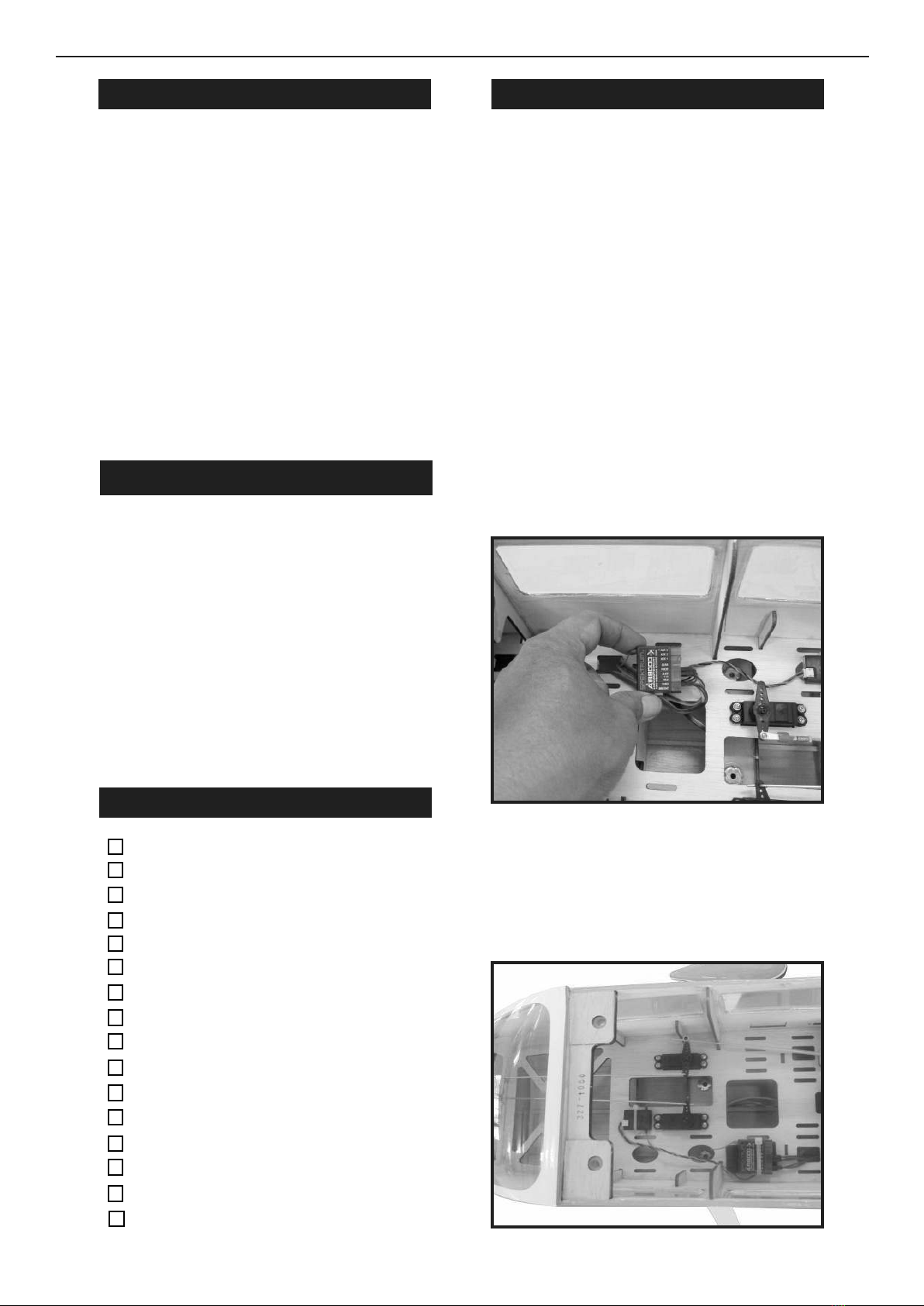
Secure the receiver in the fuselage. Use the
instructions included with the receiver for
additional mounting details. Make sure none
of the wires from the receiver interfere with
the operation of the servos.
1.
2.
�Full-range,six-plus-channel
transmitter and receiver; 6S 4000mAh
to 5000mAh LiPo battery with TX60 or
TX60 connector; LiPo battery charger
Flying weight: 8 to 10 pounds.
�Computer radio 5 channel with 6
servos.
�Glow plug to suit engine.
�Propeller to suit engine.
�Protective foam rubber for radio
system.
CESSNA TURBO SKYLANE 182 ELECTRIC 69” WINGSPAN PNP Instruction Manual.
4
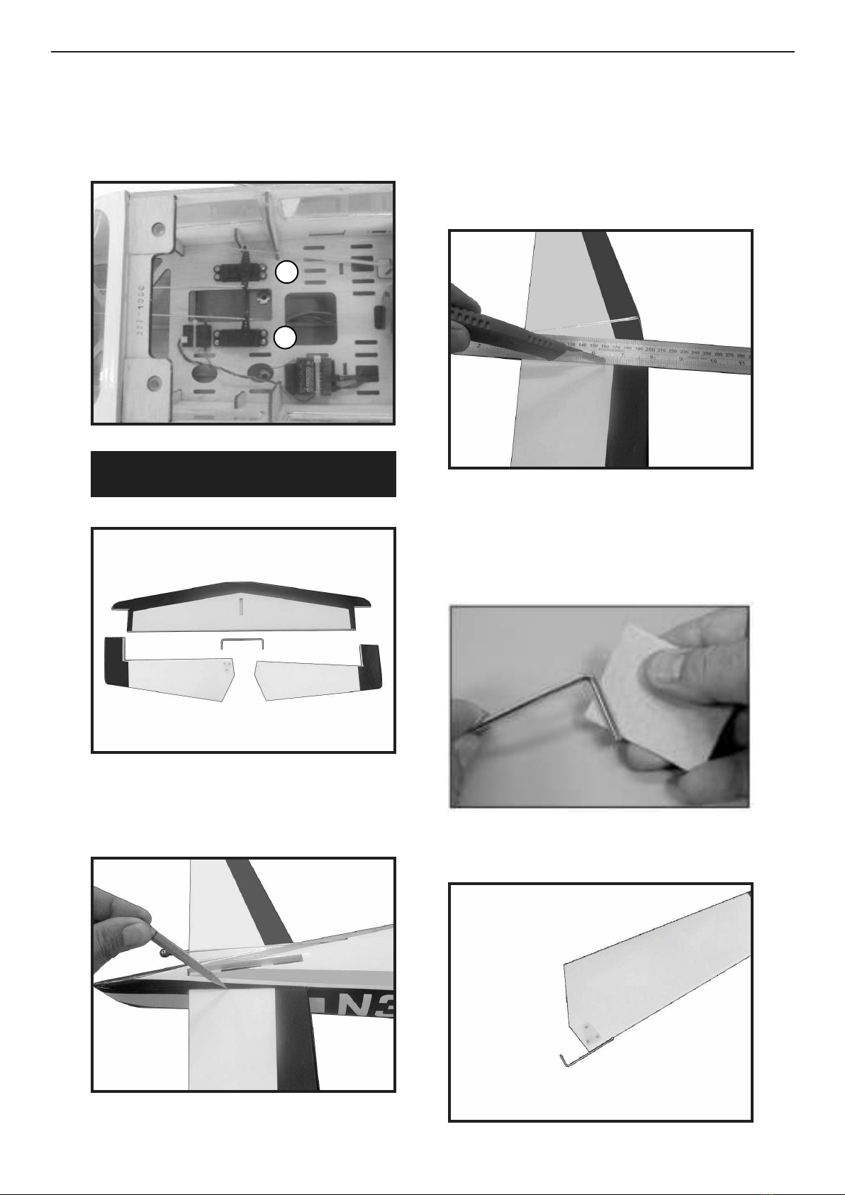
Check that the servo arms for the eleva-
tor (1) and rudder (2) are at 90-degrees to the
pushrods. Adjust the sub-trim of the radio or
reposition the servo arms as necessary.
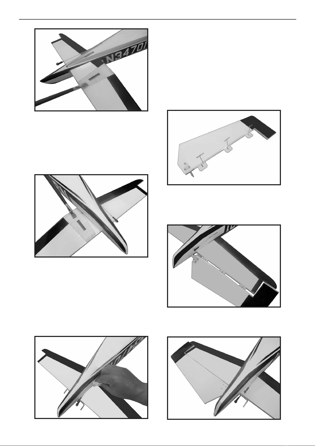
Use a ruler and carefully cut the covering
1/8 inch (3mm) inside the line drawn on the
stabilizer to remove the covering from the
center of the stabilizer. Remove the top and
bottom covering. Use care not to cut into the
underlying wood, weakening the stabilizer.
Lightly sand the elevator joiner wire where
it contacts the elevators. Use a paper towel
and isopropyl alcohol to remove any oil or
debris from the joiner.
Fit the joiner wire into the elevator halves.
Check all alignments. Mark the outline of
the fuselage on the top and bottom of the sta-
bilizer.
3.
2
1
INSTALLING THE HORIZONTAL
STABILIZER
1.
4.
2.
5.
3.
5
e elevator joiner wire must be ush with
the leading edge of the elevator as shown.
Continue the assembly of your model once
joiner wire has been correctly checked and
adjusted.
Remove the elevators from the joiner wire.
Fit the joiner wire into the fuselage, noting
the position from the previous step. is will
guarantee the joiner is placed correctly so the
elevators will be oriented as prepared inthe
previous step.
e slot for the elevator horn will be located
on the bottom right of the fuselage when the
elevators are installed.
Slide the stabilizer partially into the fuse-
lage so the wood at the center is exposed. Mix
1/2 ounce (15ml) of 30-minute epoxy. Use an
epoxy brush to apply the epoxy to the ex-
posed wood on the top of the stabilizer.
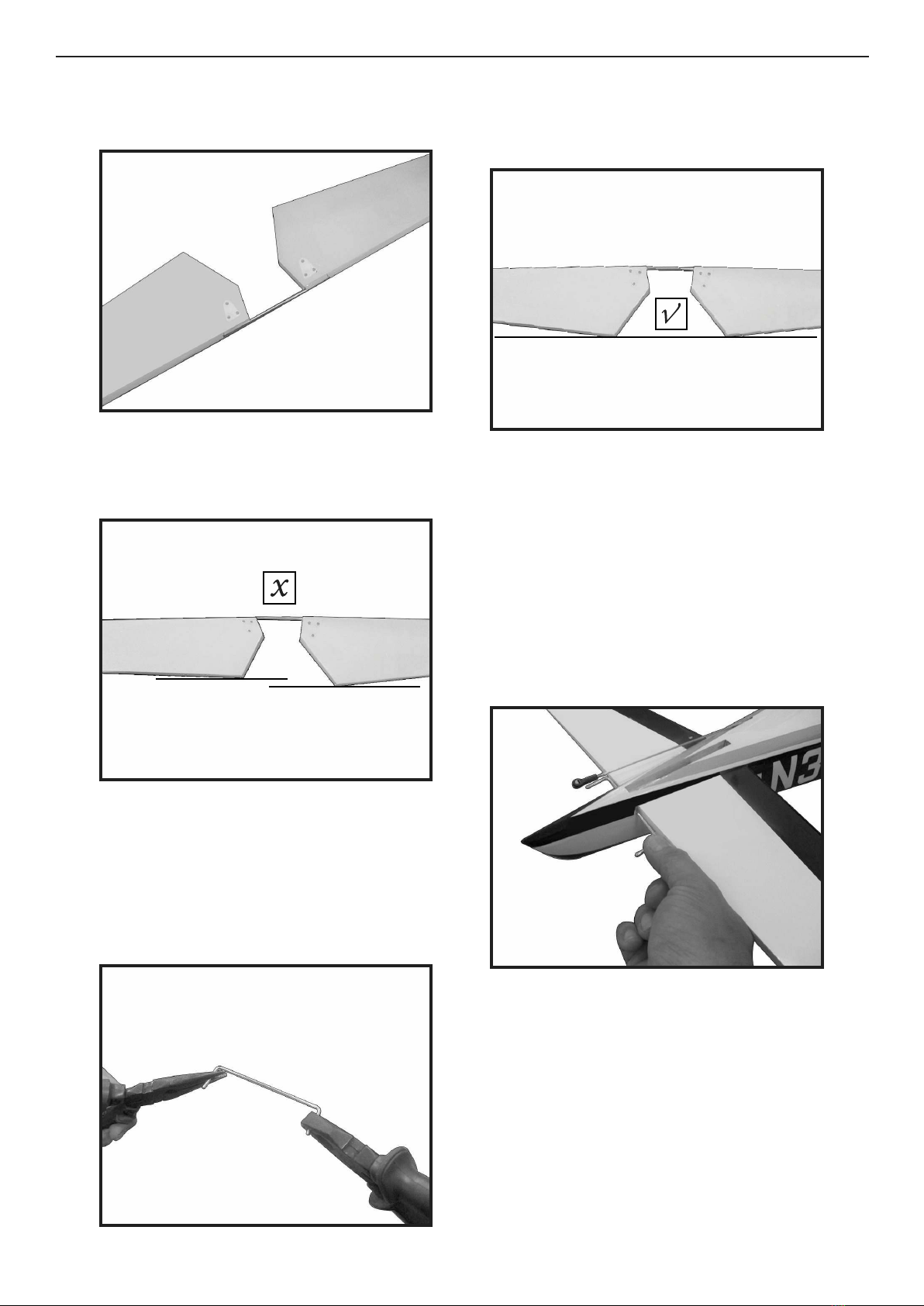
Check to make sure the elevator halves are
in alignment with each other.
If the elevators are not in alignment, use pli-
ers to bend the joiner wire slightly to bring
the halves into alignment.
Poorly aligned elevators will cause problems
with trimming your model in ight
6.
7.
10.
8.
9.
CESSNA TURBO SKYLANE 182 ELECTRIC 69” WINGSPAN PNP Instruction Manual.
6
11.
12.
14.
15.
16.
13.
Carefully turn the model over and apply
epoxy to the exposed wood on the bottom
of the stabilizer. Slide the stabilizer back into
position.
Use a pin vise and 1/16-inch (1.5mm) drill
bit to drill a hole in the center of each hinge
slot to allow the CA to wick into the hinge.
Drill holes in both the elevators and stabiliz-
er surfaces at this time. Place a T-pin in the
center of each hinge along side the slot in the
hinge. is will help center the hinge when
it is placed in the elevators. Slide the hinges
into position with the T-pin resting against
the edge of the control surface.
Fit the elevator into position on the stabi-
lizer. Guide the joiner wire and hinges into
position.
Fit the elevator so the leading edge ts tight-
ly against the trailing edge of the stabilizer.
Once the alignment of the stabilizer has
been veried, use a paper towel and isopro-
pyl alcohol to remove any excess epoxy from
the fuselage and stabilizer. Allow the epoxy to
fully cure before proceeding.
If you nd epoxy on the joiner wire, use the
paper towel and isopropyl alcohol to clean
the joiner.
Use care not to get epoxy on the elevator
joiner wire.
7
17.20.
21.
22.
18.
19.
Check the t of both elevators at this time.
Once checked, remove the elevators.
Use a toothpick to apply epoxy to the stabi-
lizer where it contacts the joiner wire.
Fit the elevators back into position. Remove
the T-pins and slide the elevators tightly
against the stabilizer. Use a paper towel and
isopropyl alcohol to remove any excess epoxy
before it begins to cure.
Check the alignment of the elevators in re-
lationship to the stabilizer at the tips. ere
should be enough gap between the balance
tab and stabilizer to they can move freely.
Do not use CA accelerator when gluing
hinges. e CA must be allowed to soak into
each hinge to provide the greatest bond be-
tween the hinges and surrounding wood.
Use a small strip of the clear packaging ma-
terial and slide it between the joiner wire and
stabilizer. Make sure the packing material
is cut so it does not obstruct the hinge slot.
Use a small piece of low-tack tape to hold the
packing material in position.
e clear packing material is used to prevent
accidentally gluing the elevators or joiner
wire to the stabilizer.
Mix a small amount of 15-minute epoxy. Use
a toothpick to apply epoxy to the joiner wire.

CESSNA TURBO SKYLANE 182 ELECTRIC 69” WINGSPAN PNP Instruction Manual.
8
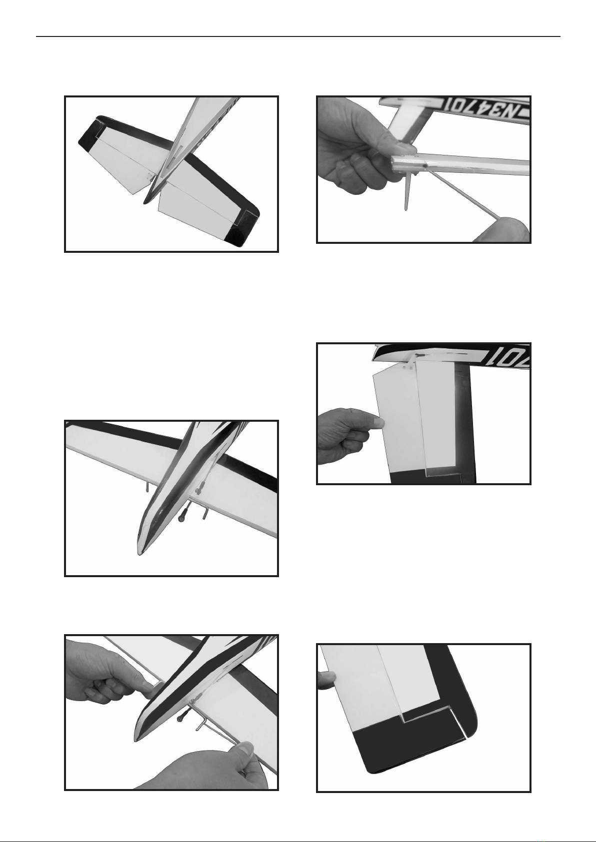
HINGING THE RUDDER
Glue the top two rudder hinges in place
using the same techniques used to hinge
the ailerons.
e lower hinge will be glued when the
/rudder assembly is attached to the fu-
selage.
1.
2.
Pen
23.
26.
24.
25.
Flex the elevator slightly, making sure to
keep the gap between the elevator and stabi-
lizer as narrow as possible. Saturate each of
the hinges using thin CA. Apply CA to the
bottom of the hinges. Allow the CA to cure
before proceeding.
Gently pull on the xed and moving surface
to make sure the hinges are glued securely. If
not, reapply thin CA to any hinges that are
found loose.
Flex the elevator slightly, making sure to
keep the gap between the elevator and stabi-
lizer as narrow as possible. Saturate each of
the hinges using thin CA. Apply CA to the
top of the hinges.
Flex the control surface through its range
of motion a few times to break-in the hinges.
is will reduce the initial load on the servo
when the surface is rst actuated.

9
5.
6.
3.
4.
C/A glue
7.
8.
9.
10.
Epoxy.

CESSNA TURBO SKYLANE 182 ELECTRIC 69” WINGSPAN PNP Instruction Manual.
10
ELEVATOR AND RUDDER
LINKAGE CONNECTIONS
Remove the 2mm nut from the elevator
ball link. read then screw Use a 1.5mm
hex wrench to thread the screw through
the center hold of the elevator control
horn.
With the radio on and the elevator stick
and trim centered, use a ruler to check
that the elevator is aligned with the sta-
bilizer.
1.
11.If the elevator and stabilizer are not
aligned, thread the ball on the elevator
in or out to correct the alignment. Make
sure to thread the ball end at the control
horn and servo arm equally as not to
damage the ball ends.
Repeat the steps for the elevator to at-
tach the rudder pushrod and ball end to
the rudder control horn.
Once the elevator and stabilizer are
aligned, use a 1.5mm hexn wrench to
tighten the screw while holding the 2mm
locknut with hemostats or needle nose
pliers.
3.
4.
2.

11
LANDING GEAR INSTALLATION
5.
1.
2.
3.
4.
5.
6.
Slide an M4 washer on the M4 x 20
socket head cap screw. Place a drop of
threadlock on the screw. Prepare all three
screws.
It is not essential to use threadlock if the
model will be disassembled for transport.

CESSNA TURBO SKYLANE 182 ELECTRIC 69” WINGSPAN PNP Instruction Manual.
12
Use the screws to attach the landing gear
to the bottom of the fuselage. Use a 3mm
hex wrench to tighten the screws. Do not
over-tighten the screws and damage the
fuselage.
7.
ead locker glue
8.
4x15mm
9.
10.
11.
C/A glue
1.
Locate the items necessary to attach the
nose landing gear that are included with
your model.
INSTALL NOSE GEAR

13
3.
2.
1.
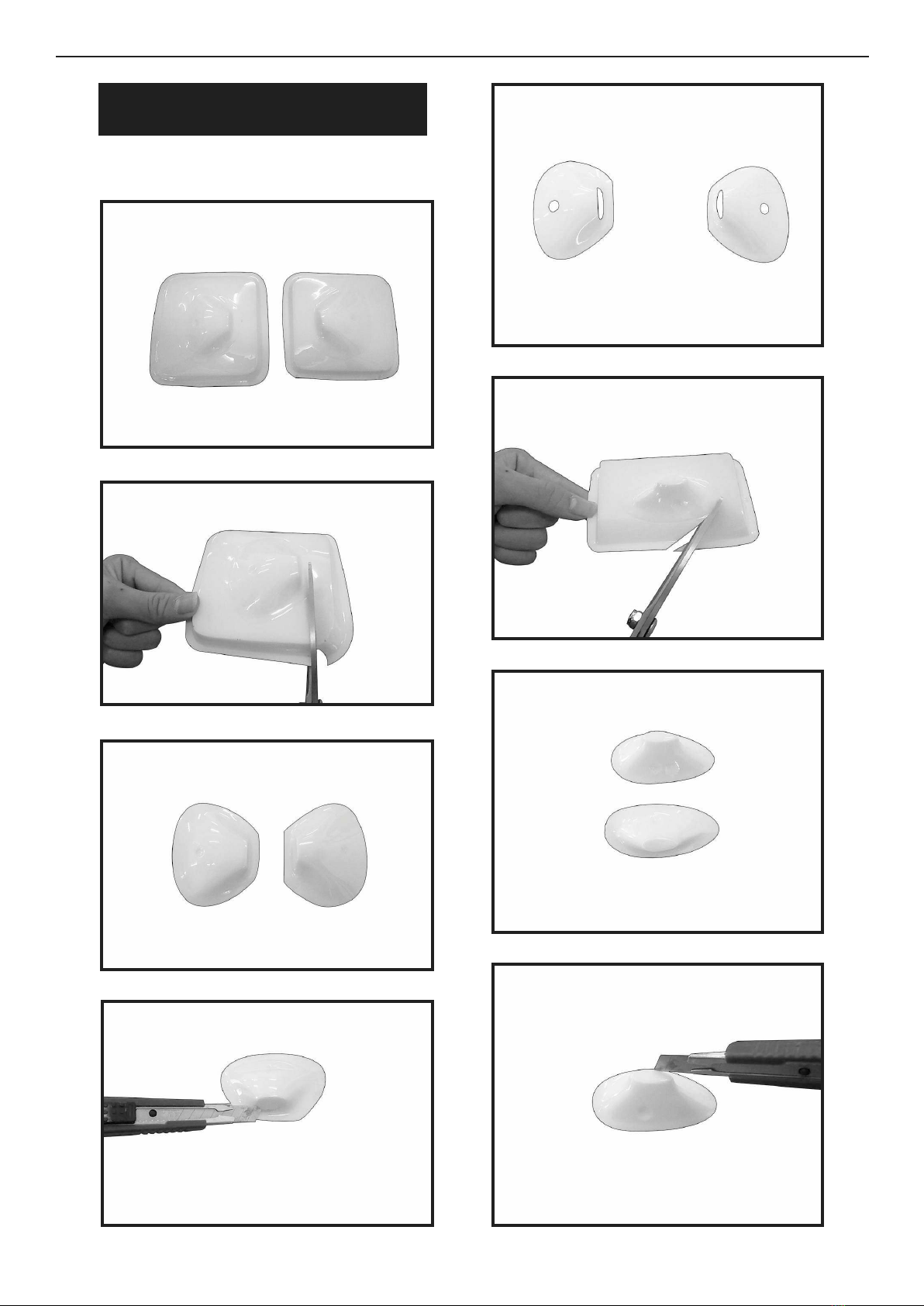
ELECTRIC POWER CONVERSION
- Please see below pictures.
3.
4.
2.
e photo shows the order of the items
as installed on the motor.
Use caution around the motor once the
propeller has been installed. e propel-
ler can cause injury if the motor starts
when the battery is connected.
MOTOR BATTERY AND
PROPELLER INSTALLATION
1.
Slide the propeller adapter, propeller
drive washer and spinner backplate on
the motor sha.

CESSNA TURBO SKYLANE 182 ELECTRIC 69” WINGSPAN PNP Instruction Manual.
14
Fit the propeller on the adapter. read
the propeller nut on the adapter and
tighten the nut using a 7/8-inch socket or
box end wrench.
Do not use pliers to tighten the nut, as
they will damage the aluminum nut over
time.
2.
3.
Fit the spinner cone in position. Position
the spinner cone so it does not contact the
propeller, Secure the spinner cone using
the provided screw and 1.5mm hex
wrench.
Secure the motor battery in the fuselage
using the hook and loop straps.
SUse hook and loop tape (not included)
between the battery and battery tray to
secure the battery during more aggressive
ying.
4.
5.
6.
7.

15
Connect the leads from the ap and
aileron extensions to the leads from the
wing. Mark each lead so they can be re-
connected in the same positions.
With the radio on and the aileron stick
and trim centered, check that the aileron
is aligned with the wing tip. Adjust the
linkage as necessary to correct the align-
ment.
1.
2.
8.
WING INSTALLATION
Slide the wing tube into the wing tube
socket.
e wing tube may be a tight t in the
socket. Polishing the wing tube with ne
sandpaper or steel wool will help ease the
installation of the wing tube. Do not force
the wing tube in the sockets as it can dam-
age the structure inside the wing.
Slide the wing panels together. ey will
t tightly together when in the correct
position.
With the radio on and the ap switch
centered, check that the ap is aligned
with the aileron. Adjust the linkage as
necessary to correct the alignment.
3.
4.
5.
CESSNA TURBO SKYLANE 182 ELECTRIC 69” WINGSPAN PNP Instruction Manual.
16
4.
8.
5.
6.
7.
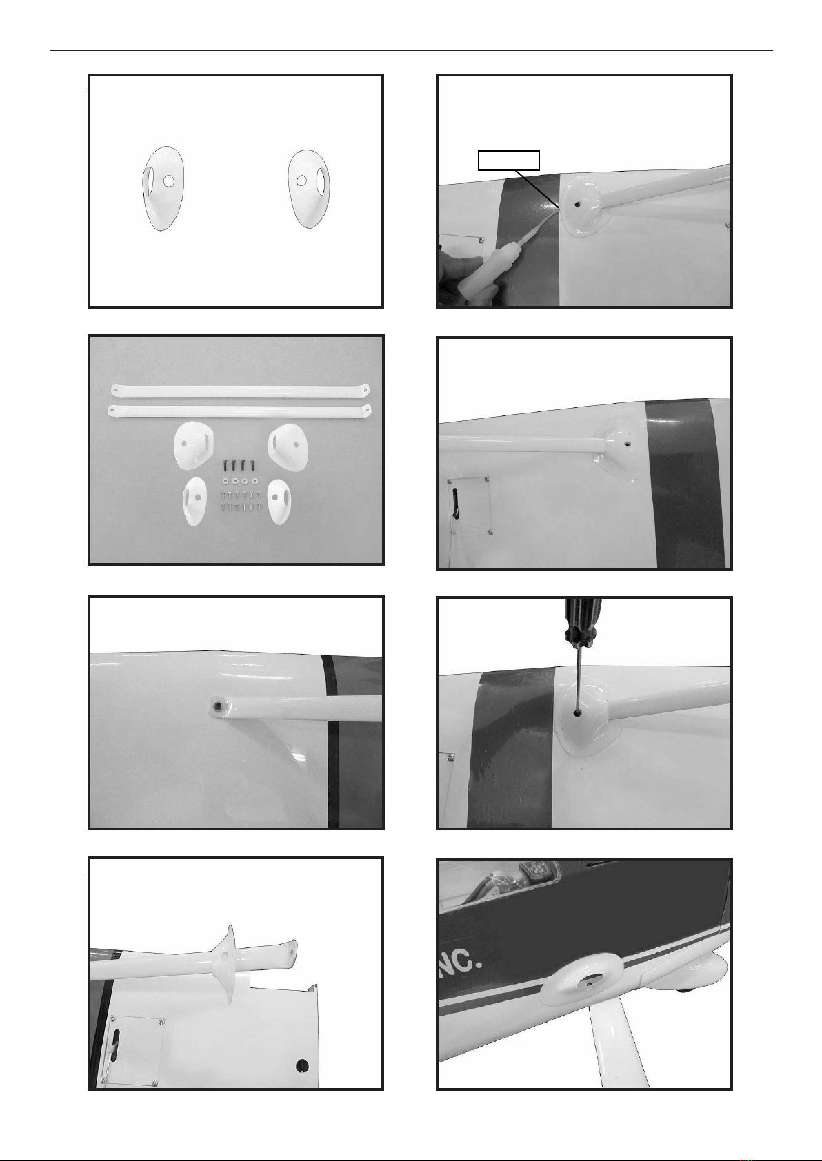
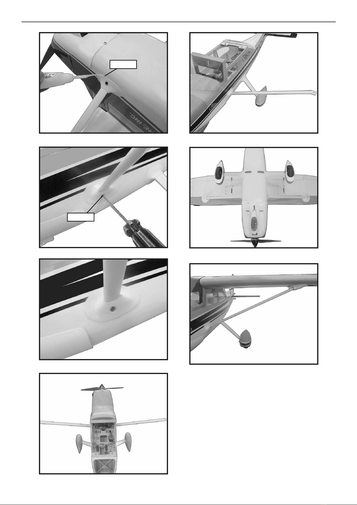
- Parts requirement.See pictures below.
INSTALLATION WING- FUSELAGE
STRUTS
1.
2.
3.
17
9.
12.
10.
11.
13.
14.
15.
C/A glue
16.
CESSNA TURBO SKYLANE 182 ELECTRIC 69” WINGSPAN PNP Instruction Manual.
18
18.
17.
19.
20.
3x12mm
Connect the leads for the aps and ai-
lerons.
Make sure the extensions will not inter-
fere with the operation of the rudder and
elevator servos.
23.
22.
21.
C/A glue

19
Place the wing bolt plate on the wing,
then thread the 1/4-20x 13/4-inch nylon
wing bolts into the blind nuts in the fuse-
lage to secure the wing.
Finger-tighten the wing bolts. Over-
tightening the wing bolts can damage the
wing structure or wing bolt plate.
24.
25.
- If all the decals are not precut, please
use scissors or a sharp hobby knife to cut
the decals from the sheet. Please be cer-
tain the model is clean and free from oily
ngerprints and dust. Position decal on
the model where desired, using the pho-
tos on the box and aid in their location.
APPLY THE DECALS
- If all the decals are precut and ready to
stick. Please be certain the model is clean
and free from oily ngerprints and dust.
Position decal on the model where de-
sired, using the photos on the box and aid
in their location.
BALANCING
An important part of preparing the air-
cra for ight is properly balancing the
model.
1) Attach the wing panels to the fuselage.
Make sure to connect the leads from the
aileron to the appropriate leads from the
receiver. Make sure the leads are not ex-
posed outside the fuselage before tight-
ening the wing bolts. Your model should
be ight-ready before balancing.
With the wing attached to the fuselage,
all parts of the model installed ( ready to
y), and empty fuel tanks, hold the mod-
el at the marked balance point with the
stabilizer level.
Li the model. If the tail drops when
you li, the model is “tail heavy” and you
must add weight* to the nose. If the nose
drops, it is “nose heavy” and you must
add weight* to the tail to balance.
*If possible, rst attempt to balance the
model by changing the position of the
receiver battery and receiver. If you are
unable to obtain good balance by doing
so, then it will be necessary to add weight
to the nose or tail to achieve the
proper balance point.
2) e recommended Center of Gravity
(CG) location for your model is (80mm)
back from the leading edge at the center
of the wing.
3) When balancing your model, make
sure it is assembled and ready for ight.
Support the plane upright at the marks
made on the wing with your gers or a
commercially available balancing stand.
is is the correct balance point for your
model.

CESSNA TURBO SKYLANE 182 ELECTRIC 69” WINGSPAN PNP Instruction Manual.
20
Ailerons:
High Rate :
Up : 20 mm
Down : 20 mm
Low Rate :
Up : 15 mm
Down : 15 mm
Elevator:
High Rate :
Up : 20 mm
Down : 20 mm
Low Rate :
Up : 15 mm
Down : 15 mm
Rudder:
High Rate :
Right : 30 mm
Le : 30 mm
Low Rate :
Right : 25 mm
Le : 25 mm
Flap:
Mid : 30mm
CONTROL THROWS
1.
80mm
15-20mm
15-20mm
25-30mm
25-30mm
Wing
Fuselage
15-20mm
15-20mm
30mm
This manual suits for next models
1
Table of contents
Other Seagull Models Aircraft manuals


