Thuli Tables 300 Elevation User manual
Table of Contents
Introduction . . . . . . . . . . . . . . . . . . . . . . . . . 2
Identication of Parts / Motor . . . . . . . . 3 - 4
Table Assembly . . . . . . . . . . . . . . . . . . . . . . 5
Headpiece Attachment & Operation . . . 6 - 10
Table Operation . . . . . . . . . . . . . . . . . . 11 - 12
Accessories . . . . . . . . . . . . . . . . . . . . . . . 13
Care & Maintenance . . . . . . . . . . . . . . 14 -15
Motor Troubleshooting . . . . . . . . . . . . . . . 16
Warranty . . . . . . . . . . . . . . . . . . . . . . . . . . 17
Overview of Products . . . . . . . . . . . . . Back
300 Elevation Owner’s Manual
Shown with Metal Base
Crescent Arm Rest
(optional)
THULI TABLES
www.thulitables.com
youtube.com/thulitables
800-458-4854
facebook.com/thulitables

2
Introduction
Rick Thuli, D.C.
President
Sincerely,
We are pleased to provide you with an aesthically beautiful chiropractic
adjusting table that is versatile and precisely engineered. It has been
thoroughly inspected and tested right down to the smallest detail before
leaving our shop. We are condent that it will provide you with many
years of reliable service.
Please take the time to read this manual carefully. It will familiarize you
with the table and instruct you on its proper operation and maintenance.
If you have any questions or comments, please contact us.
Thank you for your purchase of a 300 Elevation table.

Crescent Arm Rest
(optional)
Ankle Rest Extension
Pelvic Section
Fixed Section
Thoracic Section
Ankle Rest
Extension
Locking Knob Pelvic Cocking
Lever & Tension
Control Knob
Thoracic Cocking
Lever & Tension
Control Knob
Identification of Table Parts / Motor Information 3
MOTOR INFORMATION
Electric
Plug
Foot Pedal
Plug
Plug
Clip
Plug
Tab
Screwdriver
If the cord is not attached to
the motor, plug it in, making
sure the clip snaps onto the
tab. A at screwdriver may
be helpful to gently guide the
clip.
To extend the life of the motor, instruct the patient to get on and off at the center of the table.
Avoid elevating or lowering the table while the patient is not centered on the table.
The electric and foot pedal plugs are located at the base of the motor shaft.
Piston

Tension Control Knob
(back side)
Paper Hold-Down Wire
Pivot Block
Slide Block
Paper Hanger
Remote Control Lever
Paper Tear-Off Bar
Straight Drop /Forward
Motion Knob
Cocking Lever
Headpiece Mounting
Bracket and
Mounting Pin
Remote Control Cable
Piston Pin
T-Bar
Piston Head
Lowering Lever
Prone Arm Rest
Adjustable Strap
Flexion /Extension
Piston
Prone Arm Rest
Locking Link
4
Identification of Headpiece Parts
1. Remove the hitch pins and “O” rings from
the ankle rest extension rods.
2. Loosen both ankle rest extension lockout
knobs and slowly remove the wooden dowels
from the plastic housing (these dowels were
installed for shipping purposes only to keep
the plastic spacer from falling out of the
plastic housing).
3. Slowly insert the ankle rest extension assembly
through the frame and plastic housings.
4. Once you’ve pushed the ankle rest extension
all the way in, replace the “O” rings and hitch pins.
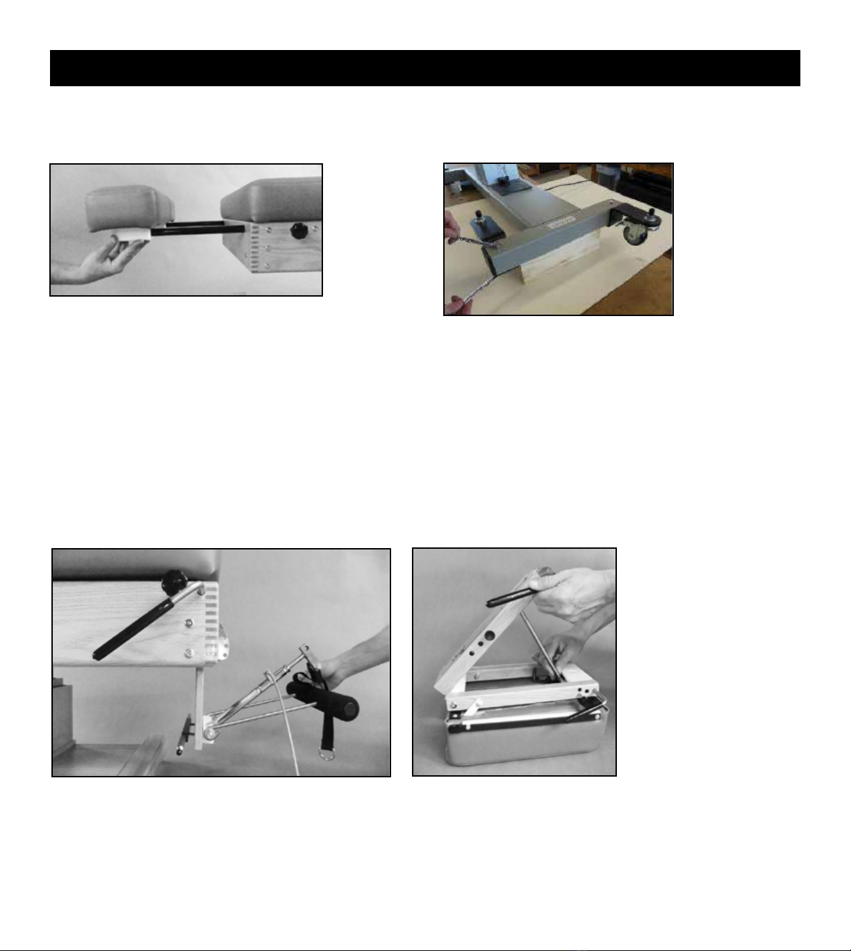
ANKLE REST ATTACHMENT
HEADPIECE ATTACHMENT
ENGAGE T-BAR
1. Place headpiece onto its cushions.
2. Lift the headpiece slide block to a 45 degree angle by grasping
the headpiece lowering lever.
3. Grasp the long rod of the T-Bar and insert it through the hole in
the locking link of the slide block.
4. Lower the slide block to a closed position by applying counterclock-
wise (downward) pressure to the headpiece lowering lever.
PISTON / PRONE ARM REST ATTACHMENT
1. Attach the piston/prone arm rest and crescent arm rest
mounting bracket (optional) to the headpiece plate,
matching up the colored dots.
2. Swing the piston/prone arm rest down out of the way
to provide room for attaching the headpiece.
5
Table Assembly
Your table will arrive in two boxes and is easy to assemble. The headpiece and ankle rest extension are packaged
separately from the table. We have included two different wrenches to assist you in the assembly process.
CHANGE WHEEL POSITION
If your table base is metal and has wheels, the two back wheels
are fastened toward the center of the table for protection
during shipping. For proper table balance, it is important to
reposition the wheels so they extend outward from the table,
as follows:
1. Prop up the back of the table, (eg. with a piece of wood).
2. Using the two 1/2” wrenches provided, remove the bolts
holding the brackets to the table.
3. Reattach the brackets so the wheels are positioned outward
from the table, as shown on right in photo.
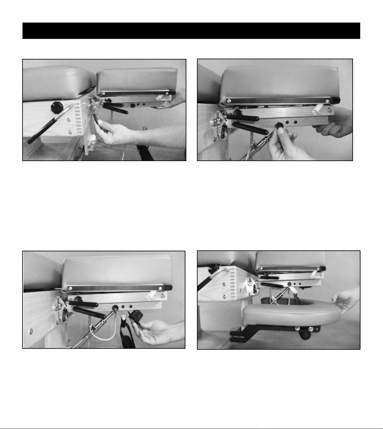
ATTACHING HEADPIECE
1. To attach the headpiece to the table, slide it between the
headpiece mounting bracket.
2. Visually line up the hole in the headpiece slide block with
the top holes of the headpiece mounting bracket and insert the
mounting pin with a twisting motion.
ATTACHING PISTON / PRONE ARM REST
1. Swing the exion/extension piston down toward the
off-centered slot in the headpiece slide block.
2. Remove the piston pin from the headpiece slide block and
raise the front end of the headpiece to allow the piston to
engage the off-centered slot.
3. Attach the exion/extension piston to the headpiece slide
block by visually lining up the holes and re-inserting the
headpiece piston pin.
4. Install the remote control lever into the bottom of the slide
block by inserting the gray cable into the narrow slot and
tilt ing the cable end of the lever into the recess until it snaps
into place. Operating this lever will allow the headpiece to
lay ush with the table cushions.
Attach Crescent Arm Rest by sliding the slotted end of the
brackets over the mounting rods. Push front of Crescent Arm
Rest down so that the block plastic bars slide over the foam pads
on the Prone Arm Rest.
CRESCENT ARM REST (optional feature)PISTON / PRONE ARM REST (continued)
6
Table Assembly
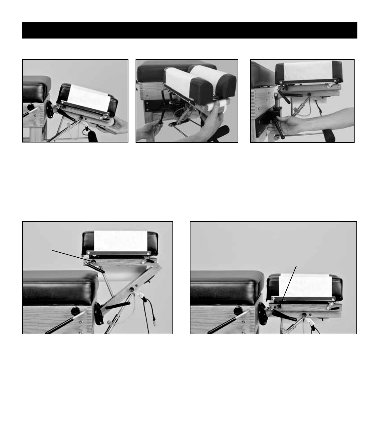
NOTE: Operating the remote control lever will allow you to
rotate the piston head to align with the off-centered slot.

7
Table Operation
1. Install a standard 8.5” roll of headpiece
paper.
2. Raise the paper hold-down wire and
tear-off bar. Advance the paper and
tuck it between the cushions.
3. Lower the hold-down wire between
the cushions, lower the tear-off bar
and tear off any excess paper.
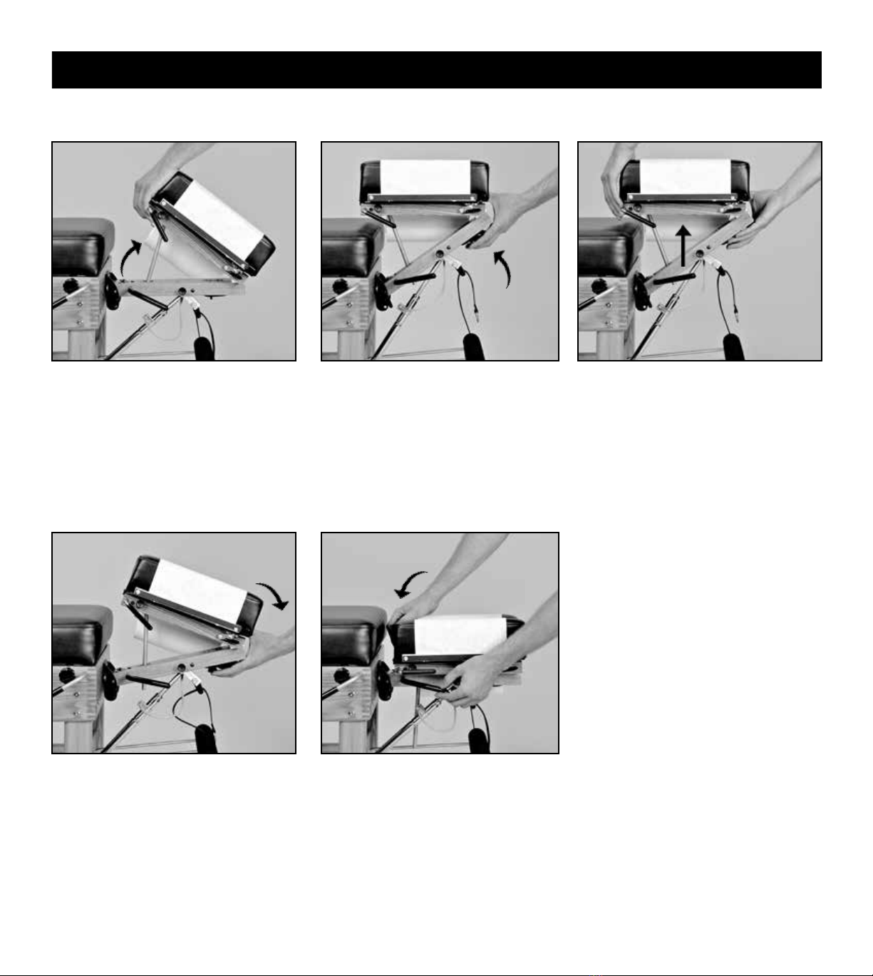
HEADPIECE PAPER
4. To advance the headpiece paper, raise
the tear-off bar, hold your nger on
the hold-down wire and pull the paper
across the cushions. Pulling the paper
in an upward direction will reduce
friction, making it easier to pull.
5. To tear off used headpiece paper, use an
upward motion while holding down the
tear-off bar.
8
Headpiece Operation
STRAIGHT DROP FORWARD MOTION DROP
Flex and extend the headpiece by
grasping the front end of the headpiece
and operating the exion/extension
control lever.
LATERAL FLEXION (optional)
To ex the headpiece laterally, turn the
lateral exion lever in a counterclockwise
direction, manually position the headpiece,
then lock it into position by tightening
the lateral exion lever. This can be done
while the headpiece is in the exed,
extended or elevated position.
LATERAL FLEXION LEVER
The position of the lateral exion lever
can be changed. With the lateral exion
lever tightened, pull the lever directly
outward, rotate to the desired position
and release.
Knob pulled out
PRIOR to cocking
Knob pushed in PRIOR to cocking
FLEXION / EXTENSION
PRIOR to cocking the headpiece, set for straight drop by
pulling out the headpiece straight drop/forward motion knob
until you feel it is “set” into position. This will be just short
of coming into contact with the cocking bar. If you pull the
knob out too far, simply push it back in and continue.
PRIOR to cocking the headpiece, set for forward motion drop by
pushing in the headpiece straight drop/forward motion knob.
Cock the headpiece with an upward motion on the headpiece cocking lever.
Please note: Be sure to change the headpiece drop function
before cocking the headpiece to prevent an ineffective drop and
damage to the drop mechanism.
Set the desired tension by turning the tension control knob clockwise (increasing tension) or counter-clockwise (decreasing tension).
9
VERTICAL ELEVATION
Headpiece Operation
2. Raise the front end of the headpiece
by operating the exion/extension
control lever.
3. With practice, steps 1 and 2 can be
combined to vertically raise the
headpiece in one smooth motion.
VERTICAL LOWERING
1. Lower the front end of the headpiece
by operating the exion/extension
control lever.
2. In one smooth motion, lower the back
end of the headpiece by lifting the
headpiece lowering lever rmly with
one hand while gently lowering the
back end of the headpiece with the
other.
IMPORTANT
Advise your patient before changing the
position of the headpiece. This is especially
important when lowering the back end of
the headpiece (step 2). Failure to do so may
result in its sudden drop, causing possible
harm to the patient.
1. Raise the back end of the headpiece
by lifting the grey grip of the cocking
lever (without operating the lever).
Caution: Do not grasp the cushions to
raise the back end, which could stretch
and damage the small springs.
10
Headpiece Operation
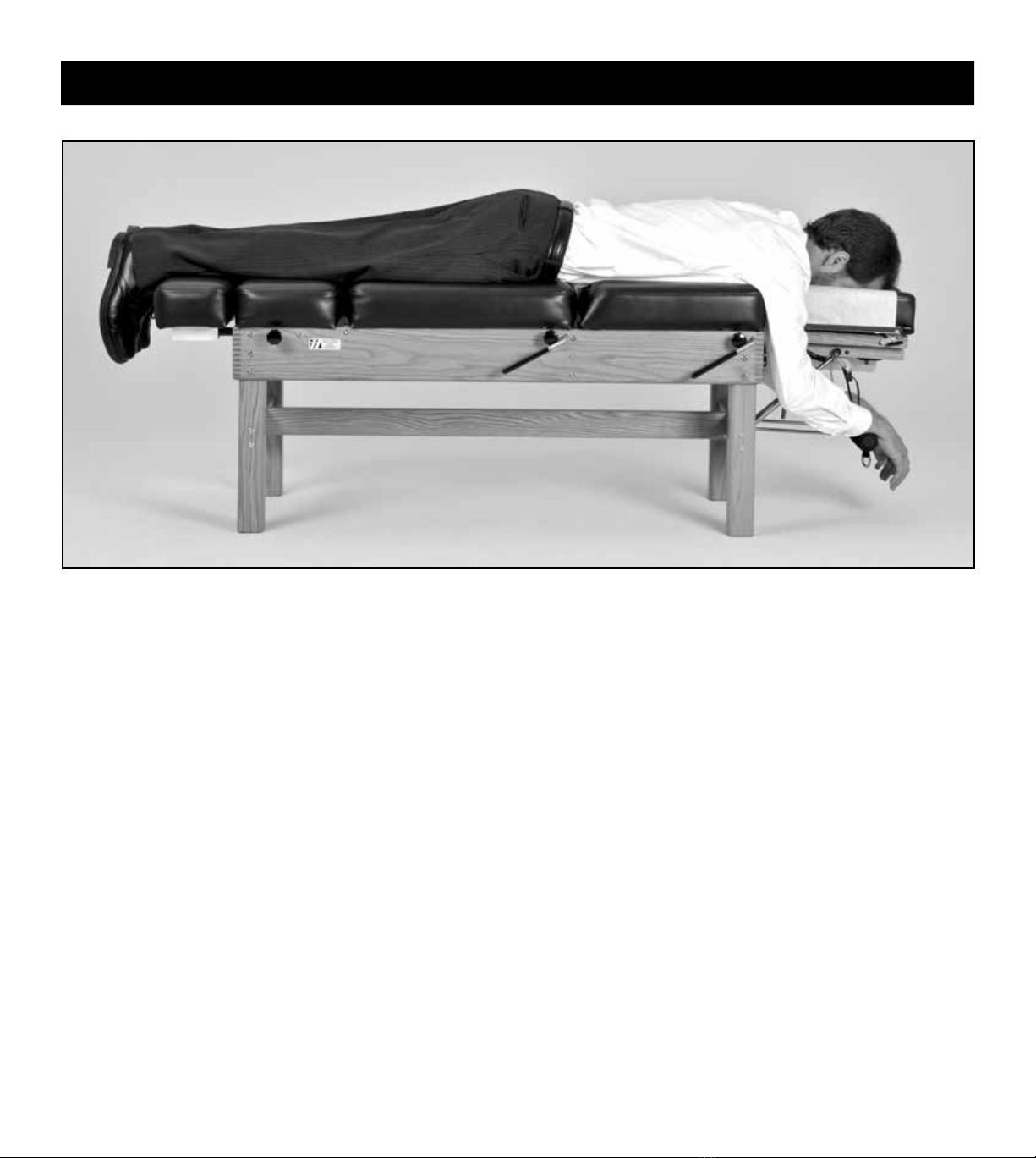
PRONE POSITION
EYE COMFORT IN PRONE POSITION
For patients who are sensitive to pressure on their eyes, slightly raise the back end of the
headpiece. This will take pressure off of the eyes by supporting the weight of the head
at the mandible and zygomatic arches. Using this maneuver, in combination with slight
exing of the headpiece, will provide additional comfort for many patients.
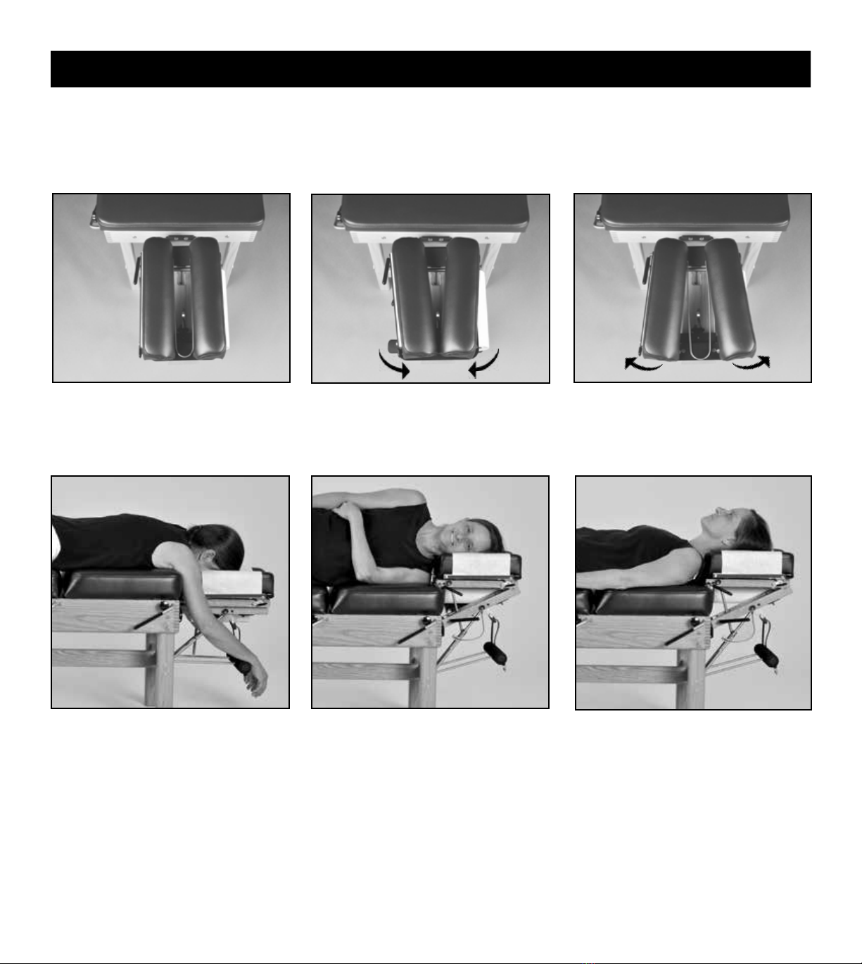
Side posture positioning of the patient’s
head for lumbo-pelvic adjusting or
toggle recoil adjusting.
SIDE POSTURE POSITION SUPINE POSITION
Position the headpiece vertically to give
maximum support of the cervical spine and
patient’s head when in a supine position.
Position the patient sufciently forward
with arms outstretched and wrists resting
comfortably on the Prone Arm Rest, which
is adjustable in height. To raise, pull on
the loop at the end of the strap. To lower,
squeeze the cam lock (to loosen the strap)
and pull down on the Prone Arm Rest
grips. Advise the patient not to apply
weight on the Prone Arm Rest while
getting up from the table.
HEADPIECE CUSHIONS: ADJUSTABLE WIDTH
Neutral position. Narrower position for smaller faces
(eg children).
Wider position takes pressure off of
the patient's eyes.
The headpiece cushions are easily adjustable in width at the front end for individualized patient comfort. Firmly pull up on the front
end of each headpiece cushion and move in (one or two notches) or out (one or two notches) to desired position. Secure cushions
by engaging locating pins into notches provided.
11
Table Operation
SETTING THE TENSION
1. Advise your patient prior to setting the tension.
2. With the patient on the table, cock the drop section with an upward
motion of the cocking lever. There must be sufcient tension on
the drop to hold the patient's head or body weight.
3. Decrease the tension control knob by turning it counter-clockwise
until the section drops.
4. Increase the tension by turning the tension control knob
clockwise 3 - 4 half turns. As a general rule, the drop is now set
for the patient's weight, which may vary according to the
practitioner’s preference.
All drops have adjustable tension control and cock with an upward
movement of the cocking lever. Following is a general guideline
for setting the tension.
PELVIC DROP
Position the patient’s anterior superior iliac spine (ASIS) at
the juncture of the pelvic and thoracic sections.
Position the patient sufciently forward with their arms
outstretched and wrists resting on the prone arm rest.
This will insure that the skin on the back of the patient’s
arms will not be pinched between the thoracic section
and the table frame when using the drop.
THORACIC DROP
Pelvic Drop Thoracic Drop

12
ANKLE REST EXTENSION
The ankle rest can be extended up to 11”
to accommodate taller patients. Shorter
patients can drop their feet into the recess
created by the extended ankle rest.
Locking knobs are provided on both sides
of the table.
ANKLE REST ELEVATION AND LOWERING (optional feature)
To ELEVATE, simply lift up on the
ankle rest.
To LOWER, lift the center of the wood
bar with one hand while gently lowering
the ankle rest with the other hand.
THORACIC INCLINE
Uses of the thoracic incline include anterior thoracic adjusting,
cervical palpation and diversied cervical adjusting. This
feature allows the practitioner to remain in a comfortable,
upright position.
CERVICAL PALPATION & ADJUSTING ANTERIOR THORACIC ADJUSTING
Table Operation
The thoracic section can be raised to a 20 degree angle. Lift the
thoracic section, swing the slant bar down and allow the rubber
tips to rest on top of the front legs (the right arm of the slant bar
will straddle the thoracic tension control knob).
12
13
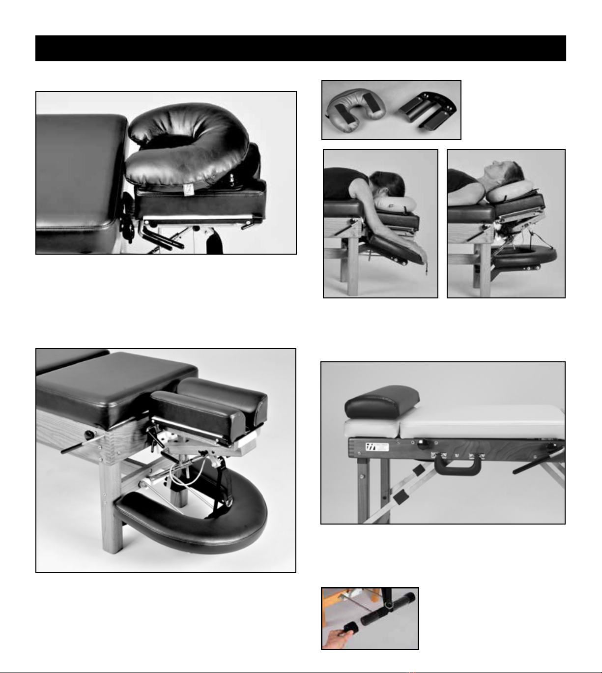
CRESCENT ARM REST
The Crescent Arm Rest provides additional forearm support in the
prone position. Simply slide both slotted ends of the bracket onto
the bolts located on the inside of the front legs and push down onto
the standard Prone Arm Rest. The Crescent Arm Rest will snap
into place and its positions are easily adjustable. Can be retrotted
to your table at anytime (minimal installation required).
Rotate the Comfort Pillow 180
degrees to provide cervical
support in the supine position.
COMFORT PILLOW
Base
Pillow
Accessories
The Comfort Pillow offers
massage quality comfort in the
prone position.
The Velcro on the
underside of the pillow
secures it to the base,
allowing for width
adjustability.
The base of the Comfort Pillow inserts into place between the
headpiece cushions. The opening is adjustable.
Comfort
Pillow
Crescent Arm Rest
Bolsters are 20" wide with a nonslip base. Choice of two
heights: 2.75" or 4.25". Use in prone position under ankles or in
supine position under knees to relax hamstrings.
BOLSTERS
2.75" x 20" Bolster (shown on Tour portable table)
PRONE ARM REST SHIELDS
Nonporous and durable plastic
shields slip over the prone arm rest
grips. Easy to sanitize.

14
Care & Maintenance
CERVICAL DROP THORACIC DROP
1. Cock the thoracic drop and raise the section to its inclined position.
Apply 3-IN-ONE oil onto the thoracic plunger.
2. Cock the pelvic drop. Raise the thoracic section as far as possible,
exposing the pelvic plunger just beyond the wood crosspiece. Using the
syringe, apply 3-IN-ONE oil onto the pelvic plunger and allow several
minutes for penetration.
Routine lubrication:
If the drops have not been lubricated on a regular basis:
1. Apply WD-40 onto the plungers (as above) and allow a few minutes
for penetration. Drop each section several times to clean from dust & debris.
2. It is important to follow the cleaning with 3-IN-ONE oil for lubrication.
DROP MECHANISMS: CLEANING & LUBRICATION
Periodic lubrication of the drop mechanisms will insure smooth, crisp drops. Use 3-IN-ONE oil every month or 500 adjustments.
If the drops have not been lubricated on a regular basis, rst clean the plungers from dust & debris using WD-40. See below.
1. Raise the headpiece and cock the drop.
2. Apply 3-IN-ONE into the hole of the plastic
block. Allow a few minutes for the oil to
penetrate before using.
If the drop has not been lubricated on a
regular basis:
Routine lubrication:
1. Apply WD-40 into the hole and then drop
the headpiece several times to clean the
plunger from dust & debris.
2. It is important to follow the cleaning with
3-IN-ONE oil for lubrication.
PELVIC DROP
3-IN-ONE OIL
Use 3-IN-ONE oil for routine lubrication of the drops.
To access the pelvic plunger, use a small syringe (one provided). Squeeze several
drops of 3-IN-ONE oil onto a nonporous surface and suction into the syringe. Save the
syringe for future use.
TENSION CONTROL ADJUSTMENT
The resistance on the tension control rod can be increased or decreased.
Locate the set screw on the bottom of the thoracic, pelvic and caudal
drop blocks. Use an 1/8" allen wrench to adjust.
Set Screw
Increase resistance: Turn the set screw clockwise. This is helpful
if the tension control rod is “backing out" while using the drop.
Decrease resistance: Turn the set screw counter-clockwise.

Care & Maintenance 15
VINYL CLEANING
1. Mild Daily Cleaning: Use dish soap and warm water (1:10) with a soft cloth. Follow with a thorough, clear water rinse.
If more cleaning is necessary, use a soft bristle brush with the same solution. Avoid harsh detergents and powdered abrasives.
Areas coming in contact with hair, body oils or perspiration should be washed frequently. Remove stains immediately to prevent
the possibility of becoming permanent.
2. Disinfecting Options:
Bleach: Dilute 4 tsp bleach in 1 quart of water in a spray bottle. Spray on vinyl, leave for 1-2 minutes and rinse well with water.
Hydrogen Peroxide (3%): Available in spray bottle. Use undiluted and leave on for 5 minutes and rinse well with water.
Alcohol (70% min): Use undiluted. Leave on for 1-2 minutes and rinse well with water.
REPLACEMENT VINYL: In the event of wear or damage, pre-sewn replacement vinyl is available from Thuli Tables.
3. Water Rinse: It is important to follow all cleaning with a thorough, clear water rinse to minimize premature deterioration of the
vinyl from extended exposure to chemicals.
14
Motor Troubleshooting 16
1. The outlet may not be working or the breaker is tripped. Try plugging in another device.
2. The electrical connection in the back of the motor may be disengaged.
3. The air lines from the foot switch to the motor may be not be fully connected or they may be kinked
or broken. If they are kinked, try to straighten them. If broken, we sell replacement air lines.
4. The foot switch may be worn out. Uplug the air lines from the foot switch and blow into both of them,
one at a time. If the foot switch is worn out, the motor will operate by doing this. Contact us for a
replacement foot pedal.
1. Squealing or screeching noise:
The electronic brake has likely failed and must be sent in for repair.
2. Clicking noise:
This is normal and may get louder with age, but functionally the motor is ne.
MOTOR IS NOT WORKING
MOTOR IS MAKING NOISE
TABLE MOVEMENT
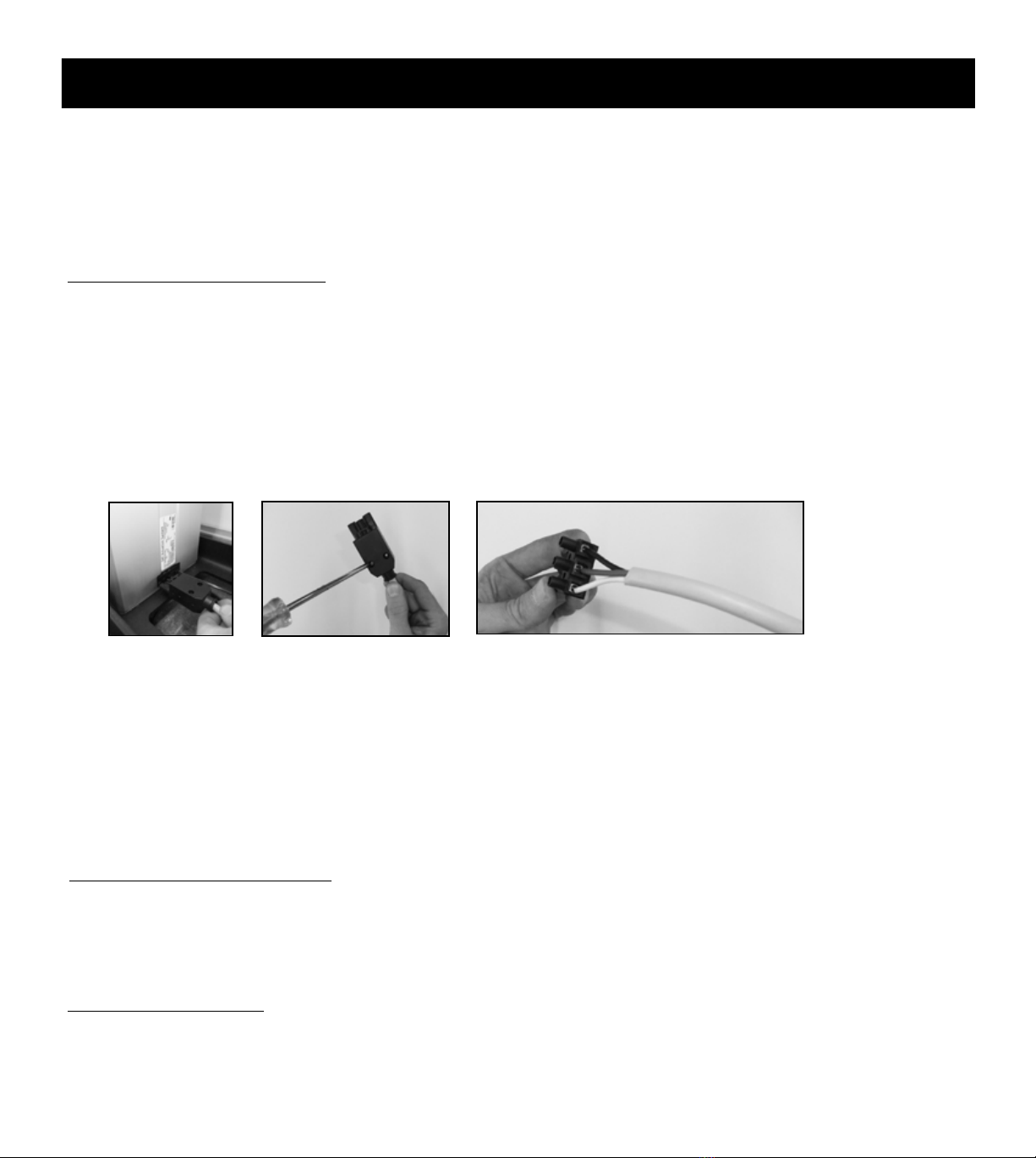
5. The wires inside the plug may be loose or disconnected.
To check this, rst uplug the motor from the electricity. Follow the steps below.
L1
N
Remove the plug
from the motor by
lifting up on the
tab (using a at
screwdriver).
Remove the cover by
removing the 2 screws
(using a Philips screw
driver).
Loosen the 3 screws (using a at screwdriver)
and re-connect the wires as follows:
110 Motors:
White wire goes into L1 (left)
Green wire goes into middle
Black wire goes into N (right)
220 Motors:
Brown wire goes into L1 (left)
Green/Yellow goes into middle
Blue goes into N (right)
When the table is in an elevated position, some movement of the table is normal. If the movement becomes
excessive and interferes with function, it is likely that the motor needs replacing.
The motor is covered by a one year warranty. Please note that the motor, like all electrical products, will eventually wear out.
The motor “life” is determined by various factors, including number of opertions, weights of patients, positioning of patients on the
table, humidity and environmental conditions. To extend the life of the motor, instruct the patient to get on and off at the center of
the table as much as possible. Avoid elevating or lowering the table if the patient is not centered on the table.
If the motor is not working properly, check the following items.,,,

If your table needs repair, whether under warranty or not, please contact us. We will determine what is needed and, at our
discretion, send you either a replacement or the necessary part for repairing. Our tables have been designed so that replacing a part
is relatively easy to do yourself. Please note that we do not cover labor costs if you hire someone to install the replacement part
on your behalf.
Our tables are designed and built to high standards and we are proud to offer a limited lifetime warranty against manufacturing
defects. This warranty is valid to the original owner and only if the table has not been altered in any way. It does not cover issues
caused by normal wear and tear, which naturally and inevitably occur as a result of normal use over time, or damage caused by
accidents, improper use and negligence. It also not does not cover the headpiece exion/extension piston and the electric motor
(on elevating tables). These two items are covered by a one year warranty against manufacturing defects.
WARRANTY
Warranty 17
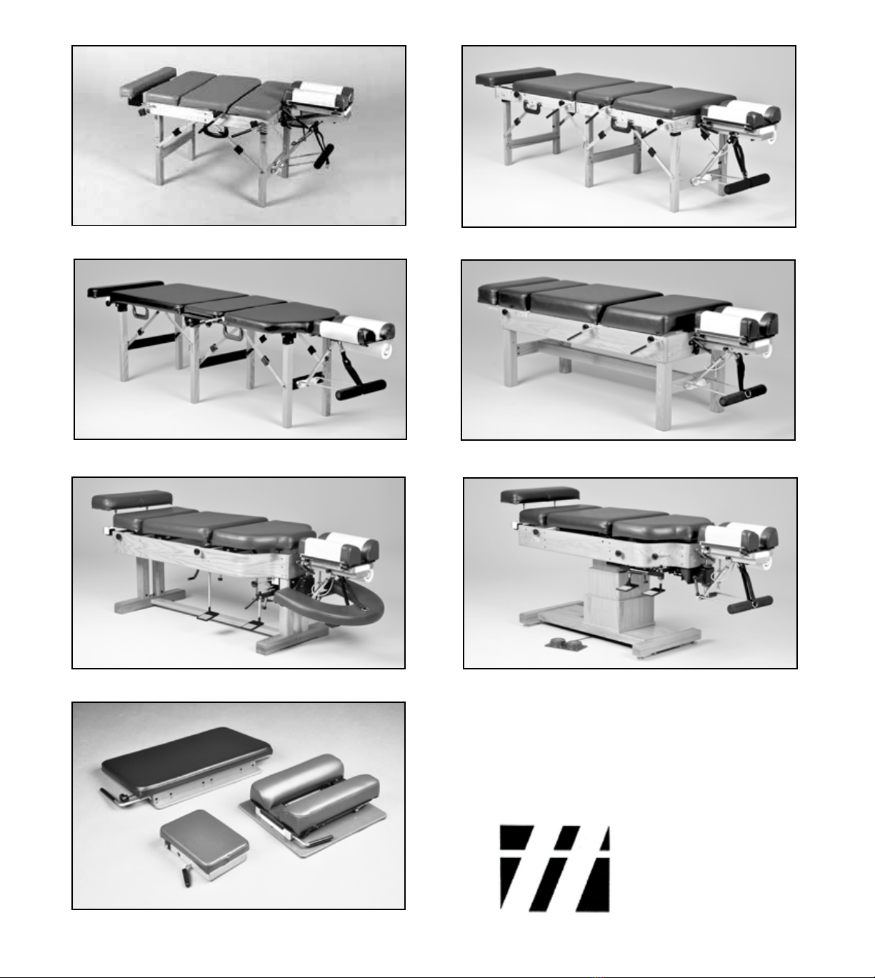
Elevation Tables
Tour Portable
300 Stationary
Sport Portable
500 Stationary
Portable Drops
Lumbo-Pelvic Drop
Extremity Drop
Speeder Board
Portable
Headpiece
Junior Portable
www.thulitables.com
608.935.9300
800.458.4854
youtube.com/thulitables
facebook.com/thulitables
This manual suits for next models
1
Table of contents
Popular Indoor Furnishing manuals by other brands

Regency
Regency LWMS3015 Assembly instructions

Furniture of America
Furniture of America CM7751C Assembly instructions

Safavieh Furniture
Safavieh Furniture Estella CNS5731 manual

PLACES OF STYLE
PLACES OF STYLE Ovalfuss Assembly instruction

Trasman
Trasman 1138 Bo1 Assembly manual

Costway
Costway JV10856 manual


