Thunder Scientific ACS3920 User manual

Thunder Scientific Corporation ACS3920 Air Compressor System 1
Document Number: ACS3920.doc - Edition 04 - Nov 2021
Operation and Maintenance Manual
for the
ACS3920
CO2 Free / Dry Air Compressor System
Thunder Scientific Corporation
623 Wyoming Blvd. SE Albuquerque, New Mexico 87123-3198
Ordering: (800) 872.7728 Tel: (505) 265.8701 FAX: (505) 266.6203
www.thunderscientific.com
Copyright © 2021 by Thunder Scientific Corporation, All Rights Reserved
®

Thunder Scientific Corporation ACS3920 Air Compressor System 2
Document Number: ACS3920.doc - Edition 04 - Nov 2021
ACS3920 Operation and Maintenance Manual
Document Edition – 004 November 2021
THUNDER SCIENTIFIC® is the registered trademark of Thunder Scientific Corporation.
All the information provided in this document is correct and true at the time of publication.

Thunder Scientific Corporation ACS3920 Air Compressor System 3
Document Number: ACS3920.doc - Edition 04 - Nov 2021
TABLE OF CONTENTS
1 INTRODUCTION...........................................................................................................4
2 SPECIFICATIONS and ENVIRONMENTAL CONDITIONS .........................................4
2.1 Specifications ......................................................................................................4
2.2 Environmental Conditions ...................................................................................4
2.3 Warranty ..............................................................................................................4
3 SAFETY GUIDELINES .................................................................................................5
4 INSTALLATION.............................................................................................................5
4.1 Unpacking ...........................................................................................................5
4.2 Location ...............................................................................................................5
4.3 Air Supply Tubing ................................................................................................6
4.4 Power ..................................................................................................................6
4.5 Remote-Control ACS Cable ................................................................................6
5 COMPONENTS and CONTROLS ................................................................................6
5.1 Power Switch.......................................................................................................6
5.2 Remote/Manual Operation Switch ......................................................................6
5.3 Hour Meter ..........................................................................................................6
5.4 Air Compressor ...................................................................................................7
5.5 Compressor Pressure Regulator.........................................................................7
5.6 Compressed Air Membrane Dryer ......................................................................7
5.7 CO2 Adsorber/Dryer Inlet Pressure Regulator ...................................................7
5.8 Outlet Pressure Regulator...................................................................................7
5.9 Dimensional Drawings.........................................................................................8
5.10 Component Locations ................................................................................ 9 & 10
6 GENERAL OPERATION.............................................................................................11
6.1 Start-up..............................................................................................................11
6.2 Compressor Pressure Adjustment ....................................................................11
6.3 Shutdown ..........................................................................................................11
7 INSPECTION and MAINTENANCE............................................................................11
7.1 Recommended Maintenance Schedule ............................................................11
7.2 Filter Inspection and Replacement....................................................................12
7.3 Storage Procedures ..........................................................................................13
7.4 Service Kit .........................................................................................................13
7.5 Heat Limit Switch...............................................................................................13
8 SCHEMATICS.............................................................................................................14
8.1 Pneumatic Schematic........................................................................................14
8.2 Electrical Schematic 110 VAC ..........................................................................15
8.3 Electrical Schematic 220 VAC ..........................................................................16
9 TROUBLESHOOTING GUIDE ...................................................................................17
10 PARTS LIST................................................................................................................17

Thunder Scientific Corporation ACS3920 Air Compressor System 4
Document Number: ACS3920.doc - Edition 04 - Nov 2021
1 INTRODUCTION
The ACS3920 Air Compressor System with integral CO2 Adsorber/Dryer is designed to be used
as the gas supply for the Thunder Scientific 3920 Low Humidity Generator. The ACS3920 Air
Compressor System consists of a vibration isolated oil-less compressor, membrane style air
dryer, CO2 Adsorber/Dryer, and adjustment regulators, all incorporated into a sound muffling
cabinet. The ACS3920 is ideal for laboratory use because of its 100 psiG pressure output at 10
L/min capability, 100% duty cycle, low sound level of less than 70 db(A), and long service life.
NOTE: When using the ACS3920 with a Model 3920 or Model 3900 low humidity generator the
working range of the generator will be limited by the lower pressure and overall dryness outputted
by the ACS3920. You will only be able to generate down to around a -70 °C frost point when
using the ACS3920. It is also important to adjust the internal Model 3920 or Model 3900
regulator to 80 to 90 psiG to assure proper pressure control.
2 SPECIFICATIONS and ENVIRONMENTAL CONDITIONS
2.1 Specifications
Voltage/Frequency: ............................................................... 110-120/115-120VAC 50/60Hz, 7A
Voltage/Frequency (Optional): ........................................... 220-240/230-240VAC 50/60Hz, 3.5A
Pressure Output (maximum): .......................................................................................... 100 psiG
Ambient Pressure Frost Point: ......................................................................................... < -73 °C
Flow Rate (maximum): ..................................................................................................... 10 L/min
Sound Level: .................................................................................................................. <70 db(A)
Duty Cycle: ........................................................................................................................... 100%
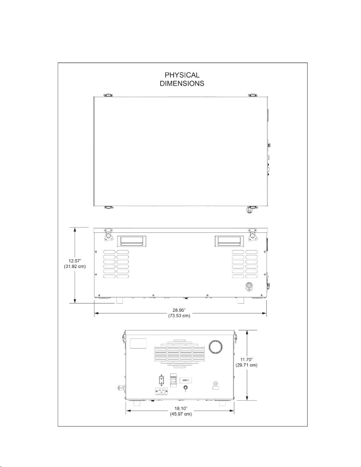
Physical Dimensions: ........................... 28.9 w" x 18.1 d" x 12.7 h" (73.4 cm x 46 cm x 32.2 cm)
Dry Weight: ........................................................................................................................ 75 lbs.
2.2 Environmental Conditions
Operating Temperature: .............................................................................................. 15 to 30 °C
Storage Temperature: ................................................................................................ > 0 to 50 °C
Humidity: .............................................................................................. 5 to 90% non-condensing
2.3 Warranty
Thunder Scientific Corporation (TSC) warrants this product to be free of defects in material and
workmanship under normal use and service when operated within the specified design limitations
for a period of 90 days from date of shipment or 2000 operating hours, whichever comes first.
TSC's obligation under this warranty shall be limited to the following: Product is returned to TSC
with transportation charges prepaid and that TSC's examination reveals the Product to be
defective, TSC, at its option, shall repair or replace at TSC's plant, any part or parts of the Product
which is or are defective. This warranty shall not apply to any Product that has become damaged
or inoperative because of ordinary wear, misuse, cold, heat, rain, excessive humidity, freeze
damage, use of improper chemicals, negligence, accident, failure to operate the product in
accordance with the instructions provided in the Operation and Maintenance Manual(s) supplied
with the product, improper maintenance, the use of accessories or attachments not
recommended by TSC or unauthorized repair or alterations.
THIS WARRANTY IS EXCLUSIVE AND IN LIEU OF ANY WARRANTY OF
MERCHANTABILITY, FITNESS FOR A PARTICULAR PURPOSE OR ANY OTHER
WARRANTY, WHETHER EXPRESS OR IMPLIED, AND ALL OTHER LIABILITIES AND
OBLIGATIONS ON THE PART OF TSC; TSC SHALL NOT BE LIABLE FOR ANY INCIDENTAL,
INDIRECT OR CONSEQUENTIAL LOSS, DAMAGE, OR EXPENSE THAT MAY RESULT
FROM ANY DEFECT, FAILURE OR MALFUNCTION OF THE PRODUCT.

Thunder Scientific Corporation ACS3920 Air Compressor System 5
Document Number: ACS3920.doc - Edition 04 - Nov 2021
All warranties: express or implied, with respect to any device or component not manufactured by
TSC but incorporated into its Product are the responsibility of the original manufacturer and shall
not affect or apply to TSC.
3 SAFETY GUIDELINES
All compressed gases, including air, can be dangerous. Know and follow all safety rules when
using compressed air and especially when disconnecting and venting compressed air lines.
Always operate the ACS3920 Air Compressor System in a clean, dry, well-ventilated area, free
of combustible materials, or solvent vapors. Operate in an open area at least 12 inches away
from any wall or obstruction that would restrict the flow of fresh air to the ventilation openings.
Restricting any of the housing openings will cause serious overheating leading to probable failure
or possible fire.
The ACS3920 Air Compressor System is an electrically powered device. Never operate in wet
conditions and never operate with cover removed. Failure to provide adequate grounding could
result in serious injury or death from electrocution. Make certain that the electrical circuit provides
proper electrical grounding, correct voltage, and adequate fuse protection.
Attempting to operate the ACS3920 with damaged or missing parts or attempting to repair with
protective cover removed can expose you to moving parts and can result in serious injury. Any
required repair should be performed by authorized personnel. Repairs attempted by unqualified
personnel can result in serious injury or death by electrocution.
The compressed air from the ACS3920 is not safe for breathing and should never be used to
supply air for human consumption. The compressed air will contain less oxygen than normal air
and will not meet breathing air standards for oxygen content. The air stream may also contain
carbon monoxide, toxic vapors, or solid particles. Breathing these contaminants can cause
serious injury or death.
Always operate the ACS3920 in a stable secure position to prevent accidental movement of the
unit.
Refer to Gast Manufacturing 71R Series Rocking Piston Oil-Less Pump Operating and
Maintenance Manual for additional specifications, service instructions, safety guidelines, hazard
and warning information.
4 INSTALLATION
4.1 Unpacking
Unpack the ACS3920 Air Compressor System carefully and inspect it for any damage that may
have occurred during shipment. If there is shipping damage, notify the carrier immediately.
Verify that the power cord, air supply tubing with connection fittings, and operation manual are
present. If possible, save shipping container for future use.
4.2 Location
Locate the ACS3920 on the floor with the outlet within five feet of the generator’s gas inlet and
at least 12 inches away from the wall or other obstructions that would restrict the flow of air to or
from the ventilation openings. The enclosure is designed to allow for proper cooling therefore
ventilation openings must remain unrestricted to maintain proper operating temperature.

Thunder Scientific Corporation ACS3920 Air Compressor System 6
Document Number: ACS3920.doc - Edition 04 - Nov 2021
4.3 Air Supply Tubing
Connect the 1/8” OD air supply tubing between the ACS3920 outlet and the generator’s gas inlet.
The VCR type fitting connections require that face seal gaskets must be used.
4.4 Power
The ACS3920 is equipped with a power receptacle (RCP1) and cord having a grounding wire
with an appropriate grounding plug. The plug must be used with an outlet that has the same
configuration and has been installed and grounded in accordance with all local codes and
ordinances.
Power of the appropriate voltage, frequency, and current capacity, as indicated on the equipment
label, is applied via the power cord to the ACS3920 power receptacle.
4.5 Remote-Control ACS Cable
This cable is used only if the 3920 Low Humidity Generator is configured with the Remote-Control
ACS option.
If configured, connect the ACS1 control cable between the humidity generator and the ACS3920
Air Compressor System. This will allow the humidity generator to start and stop the air
compressor when required for humidity generation operation.
5 COMPONENTS and CONTROLS
Refer to paragraph 5.10 for Component Locations
5.1 Power Switch
The Power Switch (CBS1) allows power to be turned ON/OFF at this location independent from
the humidity generator. The Power Switch also has a built-in circuit breaker for protection of the
ACS3920 air compressor system.
5.2 Remote/Manual Operation Switch
The Remote/Manual Switch (S1) allows the operator to select between Manual and Remote-
Control operation of the ACS3920. In Manual mode the air compressor will run continuously until
the main Circuit Breaker Switch (CBS1) is toggled off.
In remote mode the air compressor is controlled by the humidity generator if configured with the
Remote-Control ACS option.
Caution:Do not toggle “Remote/Manual” switch (S1) when compressor is running. Use
ON/OFF Circuit Breaker Switch (CBS1) to stop and then toggle “Remote/Manual” switch
to change operating modes.
5.3 Hour Meter
The Hour Meter (HM1) tracks total run hours of the ACS3920 air compressor system.

Thunder Scientific Corporation ACS3920 Air Compressor System 7
Document Number: ACS3920.doc - Edition 04 - Nov 2021
5.4 Air Compressor
The Oil-less Air Compressor (COMP) provides oil-free air regulated to a pressure of 140 psiG
(G1).
Note: Compressor pressures higher than 140 psiG will shorten the life of the compressor and
should be avoided.
5.5 Compressor Pressure Regulator
The Compressor Pressure Regulator (REG1) is a back-pressure regulator, set to 140 psiG, that
regulates the pressure from the compressor to the membrane dryer. The compressor pressure
is indicated on pressure gauge G1.
Turn the 9/32” (7mm) adjustment shaft on the compressor pressure regulator clockwise to
increase pressure and counterclockwise to decrease pressure. Set the pressure to 140 psiG as
indicated on pressure gauge G1. This is the pressure coming from the compressor and is not
the final output pressure. The final output pressure can be read on pressure gauge G3 located
inside the unit.
Note: Adjustment may be necessary after one hour of run time to keep the indicated pressure
at 140 psiG (G1).
5.6 Compressed Air Membrane Dryer
The Compressed Air Membrane Dryer (AD1) is located after the air compressor and is
specifically designed to remove water vapor from the compressed air stream prior to the CO2
Adsorber/Dryer (AD2) inlet. The membrane dryer removes water vapor from the gas stream by
the selective permeation of water molecules through polymer. Excess dry air from REG1 flows
through the shell side of the dryer purging water vapor permeate as it is vented to atmosphere.
5.7 CO2 Adsorber/Dryer Inlet Pressure Regulator
The CO2 Adsorber/Dryer Inlet Pressure Regulator (REG2) regulates the pressure from the
membrane dryer to the CO2 Adsorber/Dryer and is indicated on pressure gauge G2 (viewable
inside unit with top cover removed). This pressure is factory set to 120 psiG as indicated on the
pressure gauge (G2) and should not require adjustment.
5.8 Outlet Pressure Regulator
The Outlet Pressure Regulator (REG3) controls the pressure available from the CO2
Adsorber/Dryer to the ACS3920 outlet and is indicated on pressure gauge G3 (viewable inside
unit with top cover removed). This pressure is factory set to the maximum outlet pressure of 100
psiG as indicated on the pressure gauge (G3) and should not require adjustment.
Note: If an outlet pressure lower 100 psiG is desired, rotate the adjustment knob of REG3
counterclockwise until the desired outlet pressure is reached.

Thunder Scientific Corporation ACS3920 Air Compressor System 8
Document Number: ACS3920.doc - Edition 04 - Nov 2021
5.9 Dimensional Drawing
Refer to drawing: ACS39001-115

Thunder Scientific Corporation ACS3920 Air Compressor System 9
Document Number: ACS3920.doc - Edition 04 - Nov 2021
5.10 Component Locations
ITEM DESCRIPTION ITEM DESCRIPTION
1. Air Outlet 14. Hour Meter (HM1)
2. Air Dryer / Membrane (AD1) 15. Remote Power Jack (J1)
3. Air Dryer / CO2 Adsorber (AD2) 16. Particulate Filter (LF1)
4. On / Off Circuit Breaker Switch (CBS1) 17. Particulate Filter (LF2)
5. Circulation Fan (CF1) 18. Particulate Filter (LF3)
6. Circulation Fan (CF2) 19. Particulate Filter (LF4)
7. Air Compressor (COMP) 20. Power Receptacle (RCP1)
8. Check Valve (CV1) 21. Pressure Regulator (REG1)
9. Air Intake Filter (F1) 22. Pressure Regulator (REG2)
10. Pressure Gauge (G1) 23. Pressure Regulator (REG3)
11. Pressure Gauge (G2) 24. Remote/Manual Switch (S1)
12. Pressure Gauge (G3) 25. Solenoid Valve (SOL1)
13. Heat Limit Switch (HLS)

Thunder Scientific Corporation ACS3920 Air Compressor System 10
Document Number: ACS3920.doc - Edition 04 - Nov 2021

Thunder Scientific Corporation ACS3920 Air Compressor System 11
Document Number: ACS3920.doc - Edition 04 - Nov 2021
6 GENERAL OPERATION
6.1 Start-up
Be sure the "Air Supply Tubing" installation of paragraph 4.3 has been completed before
proceeding.
Insure the ACS3920 circuit breaker power switch is in the OFF position. Insert the power cord
into the ACS3920 power receptacle and secure receptacle clamp. Plug the power cord into an
AC mains outlet of the appropriate voltage, frequency, and current capacity as indicated by the
equipment label.
Insure the Remote/Manual switch (S1) is “Manual” to allow the air compressor system to run
continuous. Apply power to the ACS3920 using the ON/OFF circuit breaker power switch (CBS1).
The compressor will start immediately, and the pressure gauge (G1) will begin to indicate
compressor pressure of approximately 140 psiG.
Caution:Do not toggle “Remote/Manual” switch (S1) when compressor is running. Use
On/Off Circuit Breaker Switch (CBS1) to stop the compressor and then toggle
“Remote/Manual” switch to change operating modes.
6.2 Compressor Pressure Adjustment
If compressor pressure adjustment is required adjust the compressor pressure regulator (REG1)
to 140 psiG, during no-flow conditions. Turn the 9/32” (7mm) adjustment shaft clockwise to
increase pressure and counterclockwise to decrease pressure.
6.3 Shutdown
Disconnect power to the ACS3920 using the ON/OFF circuit breaker power switch.
Important: All pressure MUST be vented before disconnecting the air supply tubing or
personal injury may result.
7 INSPECTION and MAINTENANCE
7.1 Recommended Maintenance Schedule
Periodic Hours
Maintenance 100% Duty Cycle
Inlet Filter Element (F1) Inspection 1,000
Minor Compressor Service Kit 2,000
Service Kit Gast #K634
Major Compressor Rebuild 4,000
or Replacement
Replace MCA6 Desiccant Towers 4,000
(If measured output is wet)
2ea # 51386
Note: Refer to the MCA6 users guide for additional “Inspection and Maintenance” information.

Thunder Scientific Corporation ACS3920 Air Compressor System 12
Document Number: ACS3920.doc - Edition 04 - Nov 2021
7.2 Filter Inspection and Replacement
The Compressor Intake Filter requires periodic inspection. Initial inspection is suggested at
1,000 hours; then user should determine the frequency thereafter. Most problems can be
prevented by keeping the intake filter clean. A dirty intake filter will decrease compressor
performance and can decrease compressor life.
Warning: Disconnect power and be sure all pressure has been
vented before service!
1. Intake Filter Element (F1)
a. Remove ACS3920 top access cover.
b. Remove intake filter cover by pushing in and turning clockwise.
c. Replace or clean the filter element using air or vacuum.
d. Replace cover by pushing in and turning counterclockwise.
2. Particulate Filter Element (LF1) Clean or replace at 4,000 hours.
a. Remove ACS3920 top access cover.
b. Open membrane dryer retainer clips.
c. Lift compressor end of membrane dryer for access to filter.
d. Disconnect compressor outlet hose from filter inlet.
e. Remove the filter assembly from membrane dryer using a backup
wrench on inlet elbow.
f. Unscrew the adapter (1) by turning counterclockwise.
g. Remove filter (3) and replace or clean with water and blow dry.
h. Inspect bowl (5) and seal (4). If dirty, clean by wiping
the bowl with a soft dry cloth.
i. Ensure seal (2) is clean and in place then re-install filter and
rotate the adapter clockwise until snug.
j. Re-install filter assembly using a backup wrench on inlet elbow turning
clockwise.
k. Reconnect compressor outlet hose to filter inlet.
l. Snap membrane dryer back into place.
Particulate Filter (LF1)

Thunder Scientific Corporation ACS3920 Air Compressor System 13
Document Number: ACS3920.doc - Edition 04 - Nov 2021
7.3 Storage Procedures
Proper shutdown procedures must be followed to prevent compressor damage. Failure to do so
may result in premature compressor failure. The non-lubricated compressor is constructed of
ferrous metals and/or aluminum which are treated for corrosion protection but are still subject to
possible rust and corrosion when pumping condensable vapors such as water.
Follow the steps below to assure correct shutdown and storage between uses:
1. NEVER oil this non-lubricated compressor as damage will result.
2. For long term storage of the ACS3920:
a. Disconnect power from ACS3920.
b. Remove ACS3920 top access cover.
c. Disconnect the air hose at the outlet of the compressor.
d. Apply power and run the compressor "open" for at least five minutes.
e. Disconnect power, cap compressor outlet.
f. The ACS3920 is now ready for long term storage.
7.4 Service Kit
Refer to Gast Manufacturing 71R Series Rocking Piston Oil-Less Pump Operating and
Maintenance Manual for parts and procedures.
7.5 Heat Limit Switch
The non-recycling heat limit switch (HLS) trips at a predetermined set point shutting down the
circuit until reactivated. This switch is tripped in the event of elevated enclosure temperature
above the maximum operating temperature.
To reactivate limit switch:
a. Disconnect power from ACS3920.
b. Remove ACS3920 top access cover.
c. Locate and remove the black slotted limit switch cap (20).
d. Press the reset button (under black cap).
e. Replace black slotted cap.
f. Replace the ACS3920 top access cover.

Thunder Scientific Corporation ACS3920 Air Compressor System 14
Document Number: ACS3920.doc - Edition 04 - Nov 2021
PRESSURE BLEED
TO DRYER SWEEP
MEMBRANE
AIR DRYER
(AD1)
GAUGE
(G1) CHECK
VALVE
(CV1)
OUTLE T
1/4" VCR
FITTING
VENT
(S OL1)
INTAKE
FILTER
(F1)
SWEEP
EXHAUST
COMPRESSOR
(COM P)
FILTER
(LF1)
GAUGE
(G2)
FILTER
(LF4)
MCA6-11
DRYER
(AD2)
GAUGE
(G3)
REG1
COMPRESSOR PRESSURE
REGULATOR SET
TO 140 psig
PURGE
SET @ 10 L/M
REG3
SET TO
100 psiG
REG2
SET TO
120 psiG
FILTER
(LF2) FILTER
(LF3)
8SCHEMATICS
8.1 Pneumatic Schematic
Refer to drawing: 21M3920325-B
Figure 1-1

Thunder Scientific Corporation ACS3920 Air Compressor System 15
Document Number: ACS3920.doc - Edition 04 - Nov 2021
8.2 Electrical Schematic 110 VAC
110 VAC
Refer to drawing: ACS39001-115-F
Figure 1-2

Thunder Scientific Corporation ACS3920 Air Compressor System 16
Document Number: ACS3920.doc - Edition 04 - Nov 2021
8.3 Electrical Schematic 220 VAC
220 VAC
Refer to drawing: ACS39001-220-F
Figure 1-3

Thunder Scientific Corporation ACS3920 Air Compressor System 17
Document Number: ACS3920.doc - Edition 04 - Nov 2021
9 TROUBLESHOOTING GUIDE
Possible Reason No / Low High Excessive Over Won't Wet
Pressure Pressure Noise Heating Start Output
Dirty Intake Filter (F1) X X
Dirty Particulate Filter (LF1) X X
Hose Leak X X
Regulator Adjustment X X X
Worn or Damaged Compressor X X X X
Worn or Damaged Fan X X
Safety Valve "Popping Off" X X
Low Voltage X X
Blocked Ventilation Opening X X X X X
High Outlet Pressure X
Overheating X X X X X X
Heat Limit Switch Tripped X X
Excessive Flow Rate X
Desiccant Towers (End of Life) X
Note: Refer to the MCA6 users guide for additional trouble shooting for a “Wet Output”
10 PARTS LIST
Find # Qty Description Part Number
CBS1 1 Circuit Breaker Switch ACSPWRSW-1
HM1 1 Hour Meter HRMETERACS
S1 1 Switch, Remote/Manual RGSC D901RWB0
J1 1 Jack, Remote Control L722AS
COMP 1 Compressor, Gast 71R555-P322-N570X
G1 1 Gauge, Pressure G1X510
G2 & G3 2 Gauge, Pressure G6X114
REG1 1 Regulator, Back Pressure JBPREG
REG2 & 3 2 Regulator REGNG200
AD1 1 Air Dryer, Membrane MD1015
AD2 1 CO2 Adsorber/Dryer MCA6-11
CF1 & 2 2 Fan, Circulation MR2B3
F1 1 Filter Element, Air Intake 5Z768
LF1 1 Filter Element, Particulate Line 514275
LF2 & 4 2 Filter Element, Particulate Line SS-4F-K4-7
LF3 1 Filter, Particulate Line 4HEU8
CV1 1 Valve, Check 32PLCK-4
SOL1 1 Valve, Solenoid U147121-110
SSR-AC0 1 Relay, Solid State UPD Dual Output UPD2415DF
HLS 1 Switch, Heat Limit CAP-MR-140-SS
*** 2 Desiccant Towers, MCA6 Adsorber/Dryer 51386
*** 1 Service Kit, Gast Compressor K634

Thunder Scientific Corporation ACS3920 Air Compressor System 18
Document Number: ACS3920.doc - Edition 04 - Nov 2021
This Page Intentionally
Left Blank
Table of contents
Other Thunder Scientific Air Compressor manuals
Popular Air Compressor manuals by other brands

Speedaire
Speedaire 48UY04 Operating instructions & parts manual

Metabo
Metabo Classic 250 operating instructions

Clarke
Clarke 6240056 Operating & maintenance instructions

Toolex
Toolex Platinum Series instruction manual

Bitzer
Bitzer OS.53 series operating instructions

Danfoss
Danfoss MLZ Series instructions