Thunder Scientific ACS-517B User manual
Operation and Maintenance Manual
for the
ACS-517B
Air Compressor System
(UPGRADE 2014)
Thunder Scientific Corporation
623 Wyoming Blvd. SE Albuquerque, New Mexico 87123-3198
Ordering: (800) 872.7728 Tel: (505) 265.8701 FAX: (505) 266.6203
www.thunderscientific.com
Copyright © 2014 by Thunder Scientific Corporation, All Rights Reserved
®

ACS Operation and Maintenance Manual
Document Edition – 06 April 9, 2014
THUNDER SCIENTIFIC® is the registered trademark of Thunder Scientific Corporation.
All the information provided in this document is correct and true at the time of publication.
Thunder Scientific Corporation reserves the right to change any technical data without notice.

WARNING
To ensure the safety of operating personnel, and to avoid damage to this equipment:
DO NOT operate this unit without a properly grounded, properly polarized power cord.
DO NOT connect this unit to a non-grounded, non-polarized outlet.
WARNING
HIGH VOLTAGE
is used in the operation of this equipment.
SEVERE INJURY OR DEATH
may result if personnel fail to observe safety precautions.
Before working inside the equipment, turn power off and disconnect power cord.
WARNING
HIGH TEMPERATURES
exist in this equipment.
FIRE and SEVERE BURNS
may result if personnel fail to observe safety precautions.

This Page Intentionally
Left Blank

TABLE OF CONTENTS
1 INTRODUCTION ............................................................................................. 2
2 SPECIFICATIONS and ENVIRONMENTAL CONDITIONS............................ 2
2.1 Specifications......................................................................................... 2
2.2 Environmental Conditions ...................................................................... 2
2.3 Warranty ................................................................................................ 2
3 SAFETY GUIDELINES .................................................................................... 3
4 INSTALLATION ............................................................................................... 3
4.1 Unpacking .............................................................................................. 3
4.2 Location ................................................................................................. 3
4.3 Hose Installation .................................................................................... 4
4.4 Power..................................................................................................... 4
4.4.1 Extension Cord ...................................................................................... 4
5 COMPONENTS and CONTROLS................................................................... 4
5.1 Power Receptacle.................................................................................. 4
5.2 Hour Meter ............................................................................................. 4
5.3 Outlet Pressure Regulator ..................................................................... 4
5.4 Outlet Pressure Gauge .......................................................................... 4
5.5 Air Compressor ...................................................................................... 5
5.6 Membrane Air Dryer............................................................................... 5
5.7 Safety Valve ........................................................................................... 5
5.8 Dimensional Drawing ............................................................................. 5
5.9 Component Locations ............................................................................ 6
6 GENERAL OPERATION ................................................................................. 7
6.1 Set-up .................................................................................................... 7
6.2 Pressure Adjustment ............................................................................. 7
6.3 Shut-down.............................................................................................. 7
7 INSPECTION and MAINTENANCE ................................................................ 8
7.1 Recommended Maintenance Schedule................................................. 8
7.2 Filter Inspection and Replacement ........................................................ 8
7.3 Storage Procedures ............................................................................... 9
7.4 Service Kit .............................................................................................. 9
8 SCHEMATICS ............................................................................................... 10
8.1 Pneumatic Schematic .......................................................................... 10
8.2 Electrical Schematic............................................................................. 10
9 TROUBLESHOOTING GUIDE ...................................................................... 11
10 PARTS LIST .................................................................................................. 11
Thunder Scientific Corporation ACS-517B Air Compressor System 1-1
Document Number: ACS-517B.doc - Edition 06 - April 2014

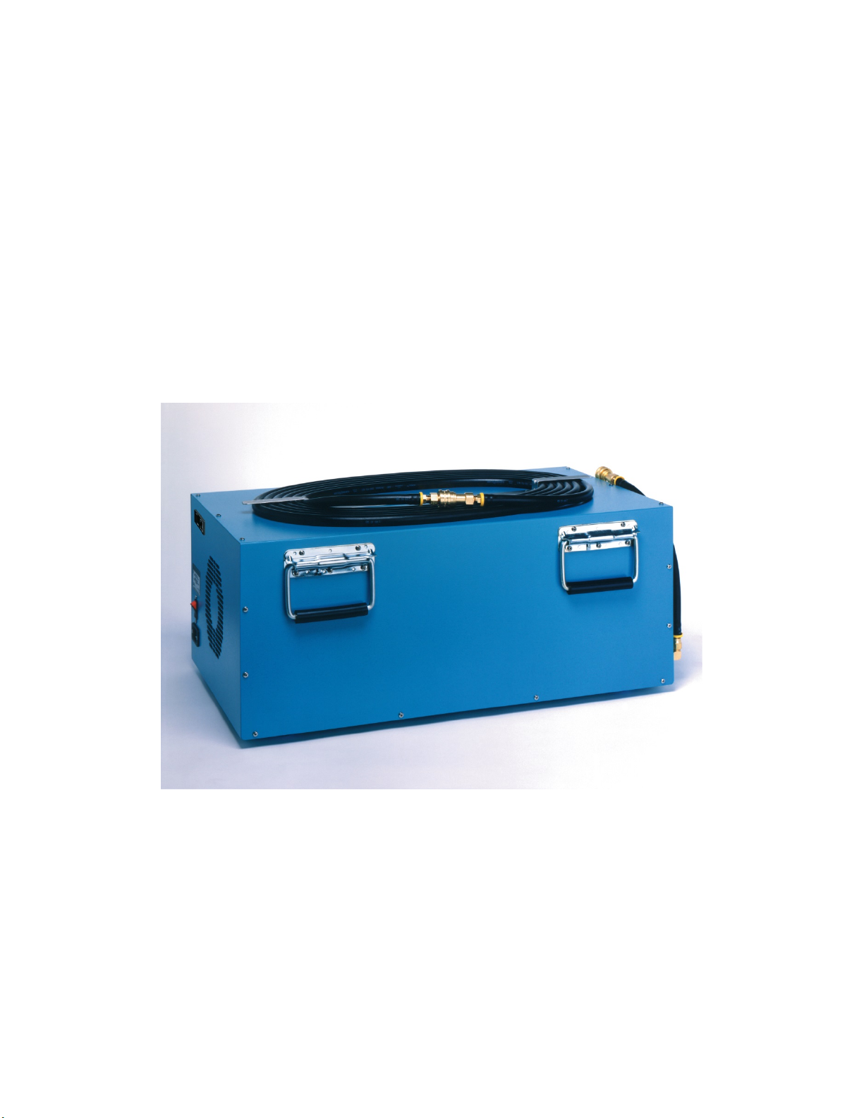
1 INTRODUCTION
The ACS-517B Oil-Less Compressed Air System is designed to be used as the air supply
for a Thunder Scientific Model 2500 humidity generator. The ACS-517B consists of a
vibration isolated oil-less piston compressor, membrane style air dryer, and output
regulator, all incorporated into a sound muffling cabinet. The ACS-517B is ideal for
laboratory use because of the its high pressure capability, 100% duty cycle capability, low
sound level of less than 70 decibels, and long service life.
2 SPECIFICATIONS and ENVIRONMENTAL CONDITIONS
2.1 Specifications
Voltage/Frequency 60Hz: ............................................................................... 115/230/60/1
Voltage/Frequency 50Hz: ..........................................................................110/220/240/50/1
Pressure Rating (MAWP): .................................................................................... 165 psiG
Pressure Dew Point............................................................. approximately 0 °C at 165 psiG
Duty Cycle: ................................................................................................................. 100%
Physical Dimensions: ... 28.875 w" x 16.125 d" x 12.89 h" (73.5 cm x 40.9 cm x 32.7 cm)
Dry Weight: ............................................................................................................. 100 lbs.
2.2 Environmental Conditions
Operating Temperature: .................................................................................... 15 to 30 °C
Storage Temperature: ...................................................................................... > 0 to 50 °C
Humidity: .................................................................................... 5 to 90% Non-condensing
2.3 Warranty
Thunder Scientific Corporation (TSC) warrants this product to be free of defects in
material and workmanship under normal use and service when operated within the
specified design limitations for a period of 90 days from date of shipment or 2000
operating hours, whichever comes first. TSC's obligation under this warranty shall be
limited to the following: the Product is returned to TSC with transportation charges prepaid
and that TSC's examination reveals the Product to be defective, TSC, at its option, shall
repair or replace at TSC's plant, any part or parts of the Product which is or are defective.
This warranty shall not apply to any Product that has become damaged or inoperative
because of ordinary wear, misuse, cold, heat, rain, excessive humidity, freeze damage,
use of improper chemicals, negligence, accident, failure to operate the product in
accordance with the instructions provided in the Owners Manual(s) supplied with the
product, improper maintenance, the use of accessories or attachments not recommended
by TSC or unauthorized repair or alterations.
THIS WARRANTY IS EXCLUSIVE AND IN LIEU OF ANY WARRANTY OF
MERCHANTABILITY, FITNESS FOR A PARTICULAR PURPOSE OR ANY OTHER
WARRANTY, WHETHER EXPRESS OR IMPLIED, AND ALL OTHER LIABILITIES AND
OBLIGATIONS ON THE PART OF TSC; TSC SHALL NOT BE LIABLE FOR ANY
INCIDENTAL, INDIRECT OR CONSEQUENTIAL LOSS, DAMAGE, OR EXPENSE THAT
MAY RESULT FROM ANY DEFECT, FAILURE OR MALFUNCTION OF THE PRODUCT.
All warranties; express or implied, with respect to any device or component not
manufactured by TSC but incorporated into its Product are the responsibility of the
original manufacturer and shall not affect or apply to TSC.
Thunder Scientific Corporation ACS-517B Air Compressor System 1-2
Document Number: ACS-517B.doc - Edition 06 - April 2014

3 SAFETY GUIDELINES
All compressed gases, including air, can be dangerous. Know and follow all safety rules
when using compressed air and especially when disconnecting and venting compressed
air lines.
Always operate the ACS-517B system in a clean, dry, well ventilated area, free of
combustible materials, or solvent vapors. Operate the ACS-517B in an open area at least
12 inches away from any wall or obstruction that would restrict the flow of fresh air to the
ventilation openings. Restricting any of the ACS-517B housing openings will cause
serious overheating leading to probable failure or possible fire.
Your ACS-517B system is powered by electricity. Like any other electrically powered
device, if not used properly it may cause electric shock. Never operate in wet conditions
and never operate with cover removed. Failure to provide adequate grounding could
result in serious injury or death from electrocution. Make certain that the electrical circuit
to which the ACS-517B is connected provides proper electrical grounding, correct voltage
and adequate fuse protection.
Attempting to operate the ACS-517B with damaged or missing parts or attempting to
repair the ACS-517B with protective cover removed can expose you to moving parts and
can result in serious injury. Any repair required should be performed by authorized
personnel. Repairs attempted by unqualified personnel can result in serious injury or
death by electrocution.
The compressed air directly from the ACS-517B is not safe for breathing, and should
never be used to supply air for human consumption. The dried air from a membrane
dryer will contain less oxygen than normal air and under some conditions the dried air will
not meet breathing air standards for oxygen content. The air stream may also contain
carbon monoxide, toxic vapors, or solid particles. Breathing these contaminants can
cause serious injury or death.
This ACS-517B can fall from a table or workbench causing damage to the compressor
and could result in serious injury. Always operate the ACS-517B in a stable secure
position to prevent accidental movement of the unit.
Refer to attached TA-5172 Piston Pump Operating and Maintenance Manual for
additional specifications, service instructions, safety guidelines, hazard and warning
information.
4 INSTALLATION
4.1 Unpacking
Unpack the ACS-517B carefully and inspect it for any damage that may have occurred
during shipment. If there is shipping damage, notify the carrier immediately. Verify that
the power cord, air hose, and manual are present. If possible, save shipping container
for future use.
4.2 Location
Locate the ACS-517B in a clean, dry and well ventilated area. The system should be
located at least 12 inches away from the wall or other obstructions that will restrict the flow
of air to the ventilation openings. The compressor enclosure is designed to allow for
proper cooling; therefore ventilation openings must remain unrestricted to maintain proper
operating temperature.
Thunder Scientific Corporation ACS-517B Air Compressor System 1-3
Document Number: ACS-517B.doc - Edition 06 - April 2014

4.3 Hose Installation
Connect the air hose via the quick connect fitting to the air tank assembly. The other end
of hose is connected to the air outlet of the ACS-517B compressor system. Open the ball
valve on the air tank before starting the system.
4.4 Power
The ACS-517B is equipped with a power receptacle and cord having a grounding wire
with an appropriate grounding plug. The plug must be used with an outlet that has the
same configuration as the grounded plug and has been installed and grounded in
accordance with all local codes and ordinances.
Power of the appropriate voltage, frequency, and current capacity, is applied via power
cord to the ACS-517B power receptacle.
4.4.1 Extension Cord
If an extension cord must be used, be sure it is a 3-wire extension cord that has a 3-blade
grounding plug, and a 3-slot receptacle that will accept the plug on the ACS-517B and is
14 gauge or larger and no longer than 50 feet.
5 COMPONENTS and CONTROLS
5.1 Power Switch
The Power Switch (CBS1) allows power to be turned on or off at this location independent
from the 2500 generator. The Power Switch also has a built-in circuit breaker.
5.2 Hour Meter
The Hour Meter (HM1) tracks total run time of the ACS-517B air compressing system.
5.3 Outlet Pressure Regulator
The Output Pressure Regulator (REG) controls the pressure available at the ACS-517B
outlet which is indicated on the pressure gauge located on the 2500’s cart. Turn the 9/32”
(7mm) adjustment shaft clockwise to increase pressure and counterclockwise to
decrease pressure.
Note: Pressures higher than 165 psi should be avoided. Higher pressures will be
indicated by the "popping off" of the compressor safety valve.
Note: Adjustment may be necessary after one hour of run time to keep the indicated
pressure at 165 psi.
5.4 Outlet Pressure Gauge
Note: If you have the Outlet Pressure Gauge (G1) it indicates the regulated pressure
available at the outlet of the ACS-517B air compressing system. This pressure is
controlled by the outlet pressure regulator.
Thunder Scientific Corporation ACS-517B Air Compressor System 1-4
Document Number: ACS-517B.doc - Edition 06 - April 2014
5.5 Air Compressor
The Oil-less Air Compressor (COMP1) provides a maximum pressure of 165 psiG at a
flow rate of 30 liters per minute or less.
5.6 Membrane Compressed Air Dryer
The Membrane Compressed Air Dryer (AD1) is located after the air compressor and is
specifically designed to remove water vapor from the compressed air stream. Typical
pressure dew points of 0 °C or less are maintained.
5.7 Safety Valve
The Safety Valve (mounted on compressor) protects the system against over pressure.
Over pressure is indicated by the "popping off" sound of the safety valve.
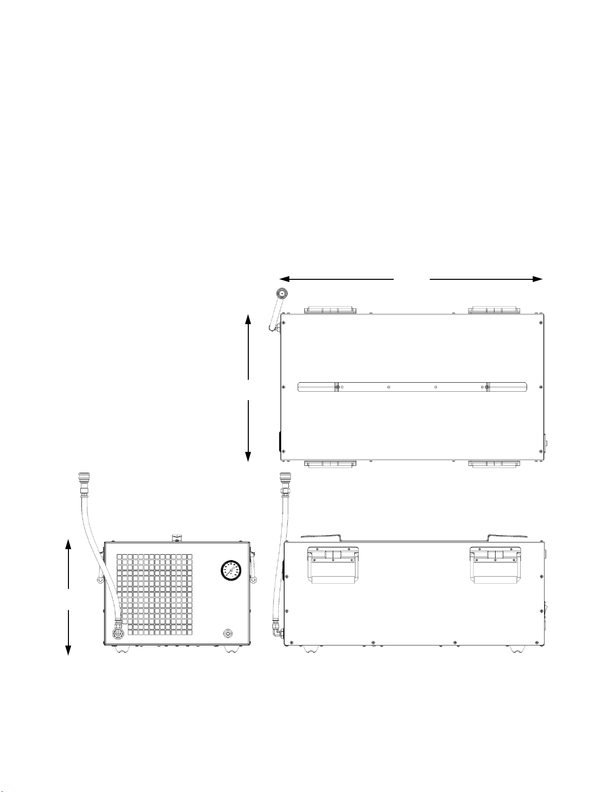
5.8 Dimensional Drawing
28.875
Top View 16.125
12.89
Left View Front View
Thunder Scientific Corporation ACS-517B Air Compressor System 1-5
Document Number: ACS-517B.doc - Edition 06 - April 2014

5.9 Component Locations
ITEM DESCRIPTION ITEM DESCRIPTION
1. On / Off Switch (CBS1) 7. Particulate Filter (LF2)
2. Power Receptacle (RCP1) 8. Circulation Fan (CF1)
3. Hour Meter (HM1) 9. Air Compressor (COMP1)
4. Pressure Gauge (G1) 10. Air Intake Filter (LF1)
5. Regulator (REG) 11. Air Dryer (AD1)
6. Air Outlet
Right View
10
3
5
9
1
2
Thunder Scientific Corporation ACS-517B Air Compressor System 1-6
Document Number: ACS-517B.doc - Edition 06 - April 2014

Left View
6 GENERAL OPERATION
6.1 Start-up
Be sure the "Hose Installation" of paragraph 4.3 has been completed before proceeding
and that the 2500 utility cart inlet valve has been opened.
Insert the power cord into the ACS-517B power receptacle. With the ACS-517B power
switch in the off position, plug the power cord into an AC mains outlet of the appropriate
voltage, frequency, and current capacity.
Apply power to the ACS-517B using the On/Off power switch. The compressor will start
and the pressure gauge will indicate approximately 165 psiG.
6.2 Pressure Adjustment
If pressure adjustment is required adjust the output pressure to 165 psiG, during no-flow
conditions, by turning the 9/32” (7mm) adjustment shaft on the regulator clockwise to
increase pressure and counterclockwise to decrease pressure.
6.3 Shut-down
Disconnect power to the ACS-517B using the On/Off power switch. Slowly open the air
tank drain valve and vent the tank pressure as indicated by the outlet pressure gauge.
6
11
7
8
Regulator
Adjustment
Access
5
4
Thunder Scientific Corporation ACS-517B Air Compressor System 1-7
Document Number: ACS-517B.doc - Edition 06 - April 2014

Important: All pressure MUST be vented before disconnecting the air supply
hose or personal injury may result.
7 INSPECTION and MAINTENANCE
7.1 Recommended Maintenance Schedule
Periodic Hours
Maintenance 100% Duty Cycle
Initial Inlet/Outlet Filter Inspection 1st 500
To establish service period
Minor Service Kit 1,500
Major Pump Rebuild or
Replacement 3,000
7.2 Filter Inspection
The Intake Filter, Outlet Filter, and Regulator Muffler require periodic inspection. Initial
inspection is suggested at 500 hours; then user should determine the frequency
thereafter. Most problems can be prevented by keeping the intake filter and particulate
filter clean. A dirty intake filter will decrease pump performance and can decrease pump
life.
Warning: Disconnect power and be sure all pressure has
been vented before service!
1. Intake a. Remove the snap-fit cover.
Filter (LF1) b. Clean felt filter using air or vacuum.
c. Replace snap-fit cover.
2. Particulate a. Remove the hose by turning the flare nut counterclockwise.
Filter (LF2) b. Unscrew the adapter (1) by turning counterclockwise.
c. Remove filter (3) and clean with water and blow dry or replace.
d. Inspect bowl (4 & 5) and seal (2). If dirty, clean by wiping
the bowl with a soft dry cloth.
e. Insure seal is clean and in place then re-install filter and
rotate the adapter clockwise until snug.
f. Re-install hose flare nut using a backup wrench turning
clockwise.
Particulate Filter (LF2)
Thunder Scientific Corporation ACS-517B Air Compressor System 1-8
Document Number: ACS-517B.doc - Edition 06 - April 2014

7.3 Storage Procedures
Proper shutdown procedures must be followed to prevent pump damage. Failure to do so
may result in premature pump failure. The non-lubricated compressor is constructed of
ferrous metals and/or aluminum which are treated for corrosion protection but are still
subject to possible rust and corrosion when pumping condensable vapors such as water.
Follow the steps below to assure correct shutdown and storage between use:
1. NEVER oil this non-lubricated compressor as damage will result.
2. For long term storage of the ACS-517B, disconnect the air hose at outlet and
apply power allowing the compressor to run "open" for at least five minutes.
After five minutes remove power and plug/cap outlet to prevent contaminants
from entering. The ACS-517B is now ready for storage.
Warning: All pressure MUST be vented before
disconnecting air supply hose!
7.4 Service Kit
Refer to Thomas TA series operating and maintenance manual for parts and procedures.
Thunder Scientific Corporation ACS-517B Air Compressor System 1-9
Document Number: ACS-517B.doc - Edition 06 - April 2014

8SCHEMATICS
8.1 Pneumatic Schematic
Figure 1-1
8.2 Electrical Schematic
Figure 1-2
Thunder Scientific Corporation ACS-517B Air Compressor System 1-10
Document Number: ACS-517B.doc - Edition 06 - April 2014

9 TROUBLESHOOTING GUIDE
Possible Reason No / Low High Excessive Over Won't
Pressure Pressure Noise Heating Start
Dirty Intake Filter X
Hose Leak X
Regulator Adjustment X X X
Worn or Damaged Compressor X X X
Worn or Damaged Fan X X
Safety Valve Leak X
Safety Valve "Popping Off" X X
Plugged Pressure Line X X
Low Voltage X X
Blocked Ventilation Opening X X X
High Outlet Pressure X
Overheating X X
10 PARTS LIST
Find # Qty Description Part Number
CBS1 1 Circuit Breaker Switch BTPWRSW-R
* PWRSW-2P
HM1 1 Hour Meter HRMETERACS
COMP1 1 Compressor, 115/230/60/1 TA5172/60
COMP1 1 Compressor, 110/220/240/50/1 * TA5172/50
G1 1 Gauge, Pressure G1X510
REG 1 Regulator, Back Pressure JBPREG
AD1 1 Air Dryer, Membrane MD1015
CF1 1 Fan, Circulation MR2B3
* MR77B3
LF1 1 Filter Element C87713
LF2 1 Filter Element G6B225
* Asterisk Indicates High Voltage Parts
Thunder Scientific Corporation ACS-517B Air Compressor System 1-11
Document Number: ACS-517B.doc - Edition 06 - April 2014

This Page Intentionally
Left Blank
Thunder Scientific Corporation ACS-517B Air Compressor System 1-12
Document Number: ACS-517B.doc - Edition 06 - April 2014
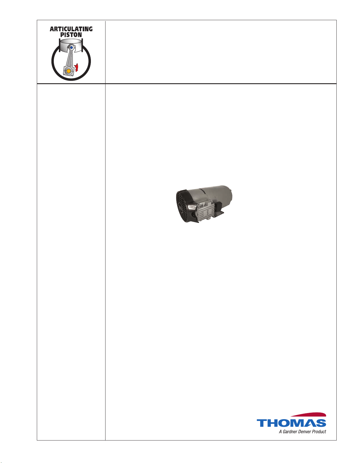
TASKAIR™ (TA) SERIES
1/2 HP
FEATURES
•Oil-less design
•Permanently lubricated and sealed bearings
•Cast iron cylinders
•PTFE piston rings and skirts
•Long, service free life
•Field service capability
•Totally enclosed motor
•Low vibration
•Quiet Operation
•Low profile
•Fifty-micron inlet filter(s)
TA-5172
MODELS
(270078)
(270073)
TA-5172
TA-5172
Thomas Division is an ISO 9001 registered company

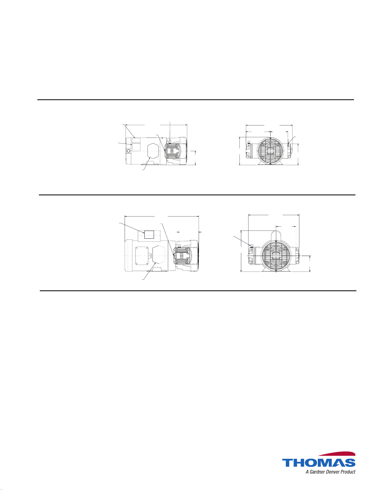
14.30 4.26
TYP BOTH
SIDES RELIEF VALVE
1/4" NPT
EXHAUST
11.20
3.50
6.95
WIRING DIAGRAM
(SUPPLIED BY MOTOR VENDOR)
(APPLIED BY THOMAS)
WARNING LABEL (RED)
(SUPPLIED BY MOTOR VENDOR)
(APPLIED BY THOMAS) MOTOR NAMEPLATE
(SUPPLIED BY MOTOR VENDOR)
1/3, 1/2, 3/4 TA Performance Data
TA SERIES | Pressure | 2
Standard Standard Standard
MODEL NUMBER
MANUFACTURING CODE
HEAD CONFIGURATION
NUMBER OF CYLINDERS
PRESSURE
cfm @ psi l/min @ bar
psi bar
0 0
10 1.0
20 2.0
25 3.0
30 5.0
35 7.0
40 8.0
50 9.0
60 10.0
70 11.0
80 12.0
90
100
110
120
130
140
150
160
175
MAX. PRESSURE
MAX. AMBIENT AIR TEMP.
MIN. AMBIENT START TEMP.
MAX. RESTART PRESSURE
MOTOR VOLTAGE/FREQUENCY
HORSEPOWER
MOTOR TYPE
CURRENT AT RATED LOAD (AMPS)
POWER AT RATED LOAD (WATTS)
STARTING CURRENT
(LOCKED ROTOR, AMPS)
MIN. FULL LOAD SPEED (RPM)
THERMAL PROTECTOR
CAPACITOR VALUE
NET WEIGHT
SHIP WEIGHT
TA-4172
270072
Pressure
2
Flow @ 115/60
cfm l/min
1.40 39.6
1.38 38.5
1.35 37.4
1.33 36.5
1.32 34.4
1.31 32.5
1.30 31.9
1.27 31.1
1.25 30.0
1.22
1.20
1.18
1.15
1.14
1.12
1.10
1.08
175 psi 12 bar
(40ºC) 104ºF
(0ºC) 32ºF
175 psi 12 bar
115/230/60/1
1/3
Capacitor Start
8.0 / 4.0 A
450 W
34.8 / 18.0 A
1725 rpm
Yes
243 mfd
45 lb. 20.4 (kg)
47 lb. 21.3 (kg)
TA-5172
270073
Pressure
2
Flow @ 115/60
cfm l/min
1.80 50.9
1.79 50.4
1.78 50.1
1.77 49.5
1.77 48.0
1.76 46.5
1.75 45.2
1.75 44.4
1.72 43.3
1.70
1.69
1.67
1.65
1.62
1.61
1.60
1.58
175 psi 12 bar
(40ºC) 104ºF
(0ºC) 32ºF
175 psi 12 bar
115/230/60/1
1/2
Capacitor Start
7.3 / 3.6 A
760 W
34.8 / 18.0 A
1725 rpm
Yes
324 mfd
51 lb. 23.1 (kg)
51 lb. 23.1 (kg)
TA-5172
270076
Pressure
2
Flow @ 230/60
cfm l/min
1.80 50.9
1.79 50.4
1.78 50.1
1.77 49.5
1.77 48.0
1.76 46.5
1.75 45.2
1.75 44.4
1.72 43.3
1.70
1.69
1.67
1.65
1.62
1.61
1.60
1.58
175 psi 12 bar
(40ºC) 104ºF
(0ºC) 32ºF
175 psi 12 bar
190/380/50/3
208-230/460/60/3
1/2
Polyphase
2.0 / 1.9 / .95 A
628 W
12.5 / 12.0 / 6.0 A
1725 / 1425 rpm
No
51 lb. 23.1 (kg)
51 lb. 23.1 (kg)
TA-5172
270078
Pressure
2
Flow @ 220/50
cfm l/min
1.43 40.4
1.42 39.9
1.41 39.6
1.40 39.2
1.40 38.4
1.39 37.3
1.39 36.7
1.38 35.9
1.37 34.8
1.36
1.35
1.34
1.32
1.31
1.30
1.28
1.26
175 psi 12 bar
(40ºC) 104ºF
(0ºC) 32ºF
175 psi 12 bar
110/220-240/50/1
1/2
Capacitor Start
8.2 / 4.1 / 4.3 A
670 W
39.0 / 19.5
A
1425 rpm
Yes
324 mfd
51 lb. 23.1 (kg)
51 lb. 23.1 (kg)
TA-6172
270080
Pressure
2
Flow @ 115/60
cfm l/min
2.40 67.9
2.39 67.1
2.37 66.8
2.36 66.1
2.36 64.9
2.35 63.5
2.34 62.2
2.33 61.4
2.31 60.3
2.30
2.28
2.26
2.25
2.22
2.21
2.20
2.18
175 psi 12 bar
(40ºC) 104ºF
(0ºC) 32ºF
175 psi 12 bar
115/230/60/1
3/4
Capacitor Start
10.6 / 5.3 A
825 W
60.0 / 30.0 A
1725 rpm
Yes
378 mfd
56 lb. 25.4 (kg)
60 lb. 27.2 (kg)
TA-6172
270082
Pressure
2
Flow @ 230/60
cfm l/min
2.40 67.9
2.39 67.1
2.37 66.8
2.36 66.1
2.36 64.9
2.35 63.5
2.34 62.2
2.33 61.4
2.31 60.3
2.30
2.28
2.26
2.25
2.22
2.21
2.20
2.18
175 psi 12 bar
(40ºC) 104ºF
(0ºC) 32ºF
175 psi 12 bar
190/380/50/3
208-230/460/60/3
3/4
Polyphase
2.8 / 2.8 / 1.4 A
800 W
17.0 / 17.0 / 8.5 A
1725 / 1425 rpm
No
56 lb. 25.4 (kg)
60 lb. 27.2 (kg)
TA-4172
270072
14.30
1/4" NPT
EXHAUST
RELIEF
VALVE
1/4" NPT
INLET
5.29
11.59
3.50 6.95
6.10 4.35
WIRING DIAGRAM
(SUPPLIED BY MOTOR VENDOR)
(APPLIED BY THOMAS)
WARNING LABEL (RED)
(SUPPLIED BY MOTOR VENDOR)
(APPLIED BY THOMAS)
MOTOR NAMEPLATE
(SUPPLIED BY MOTOR VENDOR)
TYP BOTH
SIDES
OF PORTS
C
L
OF PORT
C
L
16.30
4.26
1/4" NPT
EXHAUST
RELIEF
VALVE
4.35
11.20
3.50
9.04
WIRING DIAGRAM (WHITE)
(SUPPLIED BY MOTOR VENDOR)
(APPLIED BY THOMAS)
MOTOR NAMEPLATE
(SUPPLIED BY MOTOR VENDOR)
Dimensions
TA SERIES | Pressure | 3
270078
TA-5172
270073
TA-5172

The information presented in this material is based on technical data and test results of nom-
inal units. It is believed to be accurate and reliable and is offered as an aid to help in the selec-
tion of Thomas products. It is the responsibility of the user to determine the suitability of the
product for the intended use and the user assumes all risk and liability in connection there
with. Thomas does not warrant, guarantee or assume any obligation or liability in connection
with this information.
Models presented in this catalog are representative of the product family. Photos of prod-
ucts pictured in this catalog do not necessarily represent a specic model number. To
obtain further information for custom options, contact your local Thomas ofce.
Printed in USA
Form No. 850-4006 10/13
©2011 Gardner Denver Thomas, Inc. All rights reserved.
Thomas Division
1419 Illinois Avenue
Sheboygan, WI 53081 USA
Phone: +1 920 457 4891
Fax: +1 920 451 4237
www.gd-thomas.com
gd-thomas.com
PUMP AND COMPRESSOR SOLUTIONS FOR OEMSWORLDWIDE
Worldwide
Manufacturing and Distribution
SALES OFFICES
Australia
Austria
Brazil
China
Czech Republic
Denmark
France
Germany
Hong Kong
Italy
Japan
Korea
Netherlands
New Zealand
Sweden
Switzerland
United Kingdom
United States
MFG. LOCATIONS
Memmingen, Germany
Monroe, LA, USA
Wuxi, China
Representatives in other
countries see
www.gd-thomas.com
Other manuals for ACS-517B
1
Table of contents
Other Thunder Scientific Air Compressor manuals


