Thunder ACS-1200 User manual

Operation and Maintenance Manual
for the
ACS-1200
Air Compressor System
Thunder Scientific Corporation
623 Wyoming Blvd. SE ◆Albuquerque, New Mexico 87123-3198
Ordering: (800) 872.7728 ◆ Tel: (505) 265.8701 ◆ FAX: (505) 266.6203
www.thunderscientific.com
Copyright © 2005 by Thunder Scientific Corporation, All Rights Reserved

WARNING
To ensure the safety of operating personnel, and to avoid damage to this equipment:
DO NOT operate this unit without a properly grounded, properly polarized power cord.
DO NOT connect this unit to a non-grounded, non-polarized outlet.
WARNING
HIGH VOLTAGE
is used in the operation of this equipment.
SEVERE INJURY OR DEATH
may result if personnel fail to observe safety precautions.
Before working inside the equipment, turn power off and disconnect power cord.
WARNING
HIGH TEMPERATURES
exist in this equipment.
FIRE and SEVERE BURNS
may result if personnel fail to observe safety precautions.

TABLE OF CONTENTS
1 INTRODUCTION ............................................................................................. 1
2 SPECIFICATIONS and ENVIRONMENTAL CONDITIONS............................ 1
2.1 Specifications......................................................................................... 1
2.2 Environmental Conditions...................................................................... 1
2.3 Warranty ................................................................................................ 1
3 SAFETY GUIDELINES.................................................................................... 2
4 INSTALLATION ............................................................................................... 2
4.1 Unpacking.............................................................................................. 2
4.2 Location ................................................................................................. 3
4.3 Hose Assembly...................................................................................... 3
4.4 Power..................................................................................................... 3
4.4.1 Extension Cord ...................................................................................... 3
5 COMPONENTS and CONTROLS................................................................... 3
5.1 Power Entry Module .............................................................................. 3
5.2 Hour Meter............................................................................................. 3
5.3 Outlet Pressure Gauge .......................................................................... 3
5.4 Outlet Pressure Regulator ..................................................................... 4
5.5 Air Compressor...................................................................................... 4
5.6 Membrane Air Dryer .............................................................................. 4
5.7 Safety Valve........................................................................................... 4
5.8 Dimensional Drawing............................................................................. 4
5.9 Component Locations............................................................................ 5
6 GENERAL OPERATION ................................................................................. 6
6.1 Set-up .................................................................................................... 6
6.2 Pressure Adjustment ............................................................................. 6
6.3 Shut-down.............................................................................................. 6
7 INSPECTION and MAINTENANCE ................................................................ 6
7.1 Recommended Maintenance Schedule................................................. 6
7.2 Filter Inspection and Replacement ........................................................ 6
7.3 Shutdown and Storage Procedures....................................................... 7
7.4 Service Kit.............................................................................................. 7
8 SCHEMATICS ................................................................................................. 8
8.1 Pneumatic Schematic ............................................................................ 8
8.2 Electrical Schematic .............................................................................. 8
9 TROUBLESHOOTING GUIDE........................................................................ 9
10 PARTS LIST .................................................................................................... 9

1 INTRODUCTION
The ACS-1200 Oil-Less Compressed Air System is designed to be used as the air supply
for a Thunder Scientific Model 1200 humidity generator. The ACS-1200 consists of a
vibration isolated oil-less rocking piston compressor, membrane style air dryer, and
output regulator, all incorporated into a sound muffling cabinet. The ACS-1200 is ideal
for laboratory use because of the its high pressure capability, 100% duty cycle capability,
low sound level of less than 65 decibels, and long service life.
2 SPECIFICATIONS and ENVIRONMENTAL CONDITIONS
2.1 Specifications
Electrical Power: ............................................... 100/100-120, 7 A, 50/60 Hz, single phase
Electrical Power (optional):..........................................220-240, 3.5 A, 50 Hz, single phase
Pressure Rating (MAWP): .................................................................................... 175 psiG
Pressure Dew Point............................................................ approximately 0 °C at 170 psiG
Flow Rate: ................................................................................................................. 10 L/m
Duty Cycle: ................................................................................................................ 100%
Physical Dimensions: .................... 24 w" x 14 d" x 11.75 h" (61 cm x 35.6 cm x 29.9 cm)
Dry Weight: ............................................................................................................... 40 lbs.
2.2 Environmental Conditions
Operating Temperature: ................................................................................... 15 to 30 °C
Storage Temperature: ..................................................................................... > 0 to 50 °C
Humidity: .................................................................................... 5 to 90% Non-condensing
2.3 Warranty
Thunder Scientific Corporation (TSC) warrants this product to be free of defects in
material and workmanship under normal use and service when operated within the
specified design limitations for a period of 1 year from date of shipment or 5000 operating
hours, which ever comes first. TSC's obligation under this warranty shall be limited to the
following: the Product is returned to TSC with transportation charges prepaid and that
TSC's examination reveals the Product to be defective, TSC, at its option, shall repair or
replace at TSC's plant, any part or parts of the Product which is or are defective. This
warranty shall not apply to any Product that has become damaged or inoperative
because of ordinary wear, misuse, cold, heat, rain, excessive humidity, freeze damage,
use of improper chemicals, negligence, accident, failure to operate the product in
accordance with the instructions provided in the Owners Manual(s) supplied with the
product, improper maintenance, the use of accessories or attachments not
recommended by TSC or unauthorized repair or alterations.
THIS WARRANTY IS EXCLUSIVE AND IN LIEU OF ANY WARRANTY OF
MERCHANTABILITY, FITNESS FOR A PARTICULAR PURPOSE OR ANY OTHER
WARRANTY, WHETHER EXPRESS OR IMPLIED, AND ALL OTHER LIABILITIES AND
OBLIGATIONS ON THE PART OF TSC; TSC SHALL NOT BE LIABLE FOR ANY
INCIDENTAL, INDIRECT OR CONSEQUENTIAL LOSS, DAMAGE, OR EXPENSE
THAT MAY RESULT FROM ANY DEFECT, FAILURE OR MALFUNCTION OF THE
PRODUCT.
All warranties, express or implied, with respect to any device or component not
manufactured by TSC but incorporated into its Product are the responsibility of the
original manufacturer and shall not affect or apply to TSC.
Thunder Scientific Corporation ACS-1200 Air Compressor System 1-1
Document Number: ACS-1200.DOC - Edition 1 - July 2005

3 SAFETY GUIDELINES
All compressed gases, including air, can be dangerous. Know and follow all safety rules
when using compressed air and especially when disconnecting and venting compressed
air lines to install or modify equipment.
Always operate the ACS-1200 system in a clean, dry, well-ventilated area, free of
combustible materials, or solvent vapors. Operate the ACS-1200 in an open area at
least 12 inches away from any wall or obstruction that would restrict the flow of fresh air
to the ventilation openings. Restricting any of the ACS-1200 housing openings will cause
serious overheating leading to probable failure or possible fire.
Your ACS-1200 system is powered by electricity. Like any other electrically powered
device, if not used properly it may cause electric shock. Never operate in wet conditions
and never operate with cover removed. Failure to provide adequate grounding could
result in serious injury or death from electrocution. Make certain that the electrical circuit
to which the ACS-1200 is connected provides proper electrical grounding, correct voltage
and adequate fuse protection.
Attempting to operate the ACS-1200 with damaged or missing parts or attempting to
repair the ACS-1200 with protective cover removed can expose you to moving parts and
can result in serious injury. Authorized personnel should perform any repair required.
Repairs attempted by unqualified personnel can result in serious injury or death by
electrocution.
The compressed air directly from the ACS-1200 is not safe for breathing, and should
never be used to supply air for human consumption. The dried air from a membrane
dryer will contain less oxygen than normal air and under some conditions the dried air will
not meet breathing air standards for oxygen content. The air stream may also contain
carbon monoxide, toxic vapors, or solid particles. Breathing these contaminants can
cause serious injury or death.
This ACS-1200 can fall from a table or workbench causing damage to the compressor
and could result in serious injury. Always operate the ACS-1200 in a stable secure
position to prevent accidental movement of the unit.
Refer to attached 71R Series Rocking Piston Pump Operating and Maintenance Manual
for additional safety guidelines, hazard and warning information.
4 INSTALLATION
4.1 Unpacking
Unpack the ACS-1200 carefully and inspect it for any damage that may have occurred
during shipment. If there is shipping damage, notify the carrier immediately. Verify that
the power cord, air hose, and manual are present. If possible, save shipping container
for future use.
4.2 Location
Locate the ACS-1200 in a clean, dry and well-ventilated area. The system should be
located at least 12 inches away from the wall or other obstructions that will restrict the
flow of air to the ventilation openings. The compressor enclosure is designed to allow for
proper cooling; therefore ventilation openings must remain unrestricted to maintain
proper operating temperature.
Thunder Scientific Corporation ACS-1200 Air Compressor System 1-2
Document Number: ACS-1200.DOC - Edition 1 - July 2005

4.3 Hose Assembly
Apply Teflon tape (1 thread back from end of fitting) to hose fitting and assemble hose
fitting to air outlet of ACS-1200 using appropriate wrenches. Connect hose to fitting.
Connect other end of hose to the 1200 humidity generator.
Important: 1) The hex fittings on the air outlet of the ACS-1200 and the 1200 humidity
generator MUST be held in place with a wrench when tightening the fitting
and hose.
2) When tightening Swagelok tube fittings, tighten Swagelok nut only 1/4 turn
past finger tight.
4.4 Power
The ACS-1200 is equipped with a power receptacle and cord having a grounding wire
with an appropriate grounding plug. The plug must be used with an outlet that has the
same configuration as the grounded plug and has been installed and grounded in
accordance with all local codes and ordinances.
Power of the appropriate voltage, frequency, and current capacity, is applied via power
cord to the ACS-1200 power entry module.
4.4.1 Extension Cord
If an extension cord must be used, be sure it is a 3-wire extension cord that has a 3-
blade grounding plug, and a 3-slot receptacle that will accept the plug on the ACS-1200
and is 14 gauge or larger and no longer than 50 feet.
5 COMPONENTS and CONTROLS
5.1 Power Entry Module
The Power Entry Module (PEM) allows insertion of the removable power cord, houses
the On/Off power switch, and also houses the 10 amp time-delay fuse (FS1).
5.2 Hour Meter
The Hour Meter (HM1) tracks total run time of the ACS-1200 air compressing system.
5.3 Outlet Pressure Gauge
The Outlet Pressure Gauge (G1) indicates the regulated pressure available at the outlet
of the ACS-1200 air compressing system. This pressure is controlled by the outlet
pressure regulator.
5.4 Outlet Pressure Regulator
The Output Pressure Regulator (REG) controls the pressure available at the ACS-1200
outlet, which is indicated on the outlet pressure gauge. Turn slotted adjustment screw
clockwise to increase pressure and counterclockwise to decrease pressure.
Note: Pressures higher than 175 psi will be indicated by the "popping off" of the safety
valve and should be avoided.
Thunder Scientific Corporation ACS-1200 Air Compressor System 1-3
Document Number: ACS-1200.DOC - Edition 1 - July 2005

5.5 Air Compressor
The Oil-less Air Compressor (COMP) provides a maximum pressure of 175 psiG at a
flow rate of 10 liters per minute or more.
5.6 Membrane Compressed Air Dryer
The Membrane Compressed Air Dryer (AD1) is located after the air compressor and is
specifically designed to remove water vapor from the compressed air stream. Typical
pressure dew points of 0 °C or less are maintained.
5.7 Safety Valve
The Safety Valve (mounted on compressor) protects the system against pressures above
175 psiG. Pressures higher than 175 psi will be indicated by the "popping off" sound of
the safety valve.
5.8 Dimensional Drawing
11.73
14.00
24.00
To
p
View
Rear View Left View
Thunder Scientific Corporation ACS-1200 Air Compressor System 1-4
Document Number: ACS-1200.DOC - Edition 1 - July 2005
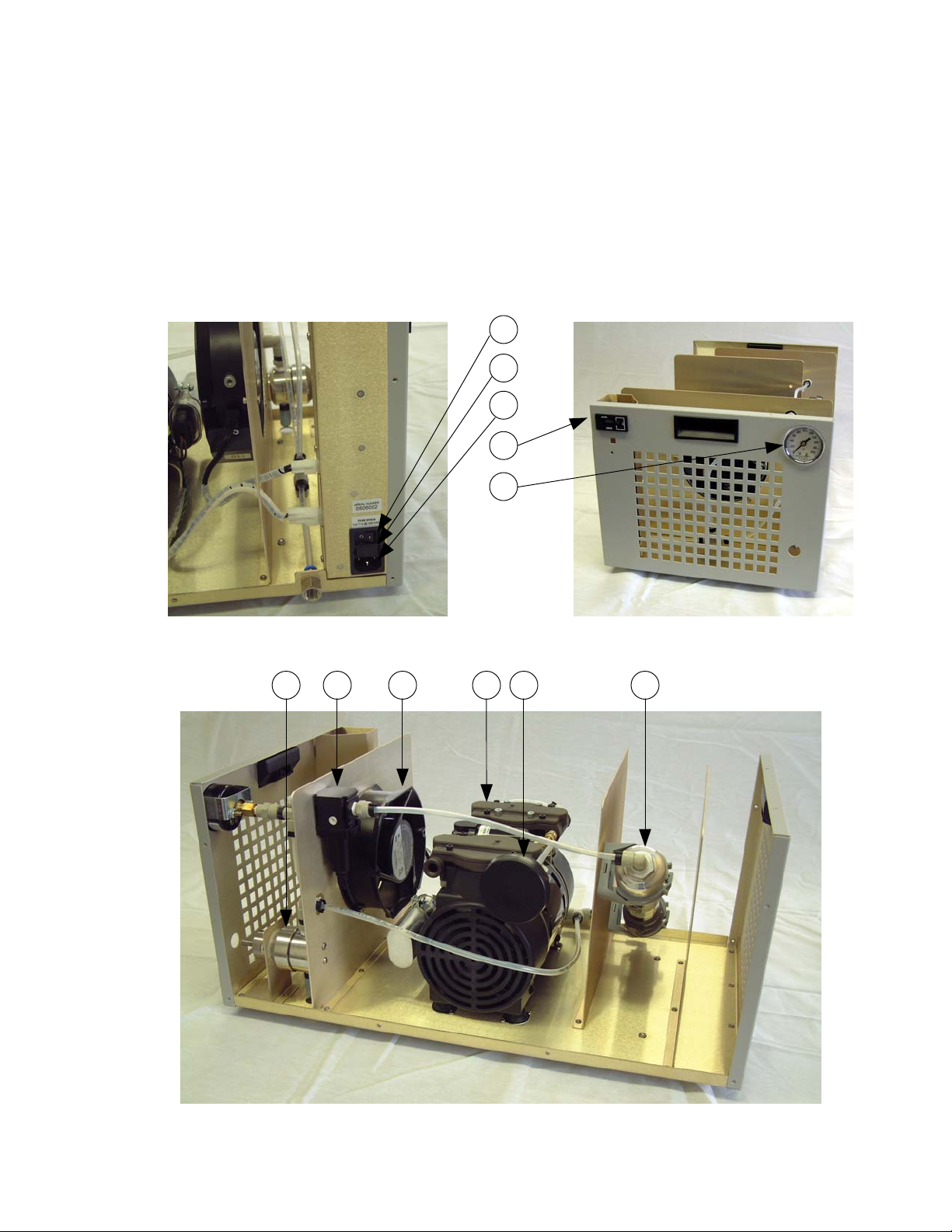
5.9 Component Locations
ITEM DESCRIPTION ITEM DESCRIPTION
1. On / Off Switch 7. Outlet Filter (LF2)
2. Fuse (FS1) 8. Circulation Fan (CF1)
3. Power Cord Receptacle 9. Air Compressor (COMP)
4. Hour Meter (HM1) 10. Air Intake Filter (LF1)
5. Pressure Gauge (G1) 11. Air Dryer (AD1)
6. Regulator (REG)
Rear View
Rear View Left View
2
910 11
4
5
7 86
3
1
Front View
Thunder Scientific Corporation ACS-1200 Air Compressor System 1-5
Document Number: ACS-1200.DOC - Edition 1 - July 2005

6 GENERAL OPERATION
6.1 Start-up
Be sure the "Hose Assembly" of paragraph 4.3 has been completed before proceeding.
Insert the power cord into the ACS-1200 power receptacle. With the ACS-1200 power
switch in the off position, plug the power cord into an AC mains outlet of the appropriate
voltage, frequency, and current capacity.
Apply power to the ACS-1200 using the On/Off power switch. The compressor will start
and the outlet pressure gauge will indicate approximately 170 psiG.
6.2 Pressure Adjustment
If pressure adjustment is required adjust the output pressure to 170 psiG, during no-flow
conditions, by turning the slotted adjustment screw on the regulator clockwise to increase
pressure and counterclockwise to decrease pressure.
6.3 Shut-down
Disconnect power to the ACS-1200 using the On/Off power switch. The compressor will
shutdown and the pressure will slowly vent as indicated by the outlet pressure gauge.
Important: All pressure MUST be vented before applying power again to the
ACS-1200 or the compressor will not start and will possibly blow the power input
fuse. All pressure must also be vented before disconnecting the air supply hose
or severe personal injury may result.
7 INSPECTION and MAINTENANCE
7.1 Recommended Maintenance Schedule
Periodic Hours
Maintenance 100% Duty Cycle
Initial Inlet/Outlet Filter Inspection 1st 500
To establish service period
Inlet/Outlet Filter Inspection User Determined
Replace when necessary
Minor Service Kit 15,000
7.2 Filter Inspection and Replacement
The Intake Filter, Outlet Filter, and Regulator Muffler require periodic inspection and
replacement. Initial inspection is suggested at 500 hours, then user should determine
the frequency thereafter. Most problems can be prevented by keeping the filters and
muffler clean. A dirty intake filter will decrease pump performance and can decrease
pump life.
Warning: Disconnect power and be sure all pressure has
been vented before service!
Thunder Scientific Corporation ACS-1200 Air Compressor System 1-6
Document Number: ACS-1200.DOC - Edition 1 - July 2005

1. Intake a. Remove the snap-fit cover.
Filter (LF1) b. Clean or replace felt filter.
c. Replace snap-fit cover.
2. Outlet a. Remove bowl by turning counterclockwise.
Filter (LF2) b. Unscrew baffle by turning counterclockwise.
c. Remove filter and clean or replace.
d. Inspect bowl and seal. If bowl is dirty, clean by wiping
the bowl with a soft dry cloth.
e. Insure seal is clean and in place then re-install bowl and
rotate clockwise to lock securely in place.
3. Interstage a. Remove bowl by turning counterclockwise.
Filter (LF3) b. Remove filter by turning slotted screw counterclockwise.
c. Inspect filter, replace filter if dirty (do not over tighten).
d. Inspect bowl. If bowl is dirty, clean by wiping
the bowl with a soft dry cloth.
e. Insure seal is clean and in place then re-install bowl,
rotate bowl clockwise to tighten.
7.3 Shutdown and Storage Procedures
Proper shutdown procedures must be followed to prevent pump damage. Failure to do
so may result in premature pump failure. The non-lubricated compressor is constructed
of ferrous metals and/or aluminum, which are treated for corrosion protection but are still
subject to possible rust and corrosion when pumping condensable vapors such as water.
Follow the steps below to assure correct shutdown and storage between uses:
1. NEVER oil this non-lubricated compressor, as damage will result.
2. For long-term storage of the ACS-1200, disconnect the air hose and apply
power allowing the compressor to run "open" for at least five minutes. After
five minutes remove power and plug/cap outlet to prevent contaminants from
entering. The ACS-1200 is now ready for storage.
Warning: All pressure MUST be vented before
disconnecting air supply hose!
7.4 Service Kit
Refer to Gast 72R operating and maintenance manual for parts and procedures.
Thunder Scientific Corporation ACS-1200 Air Compressor System 1-7
Document Number: ACS-1200.DOC - Edition 1 - July 2005
8SCHEMATICS
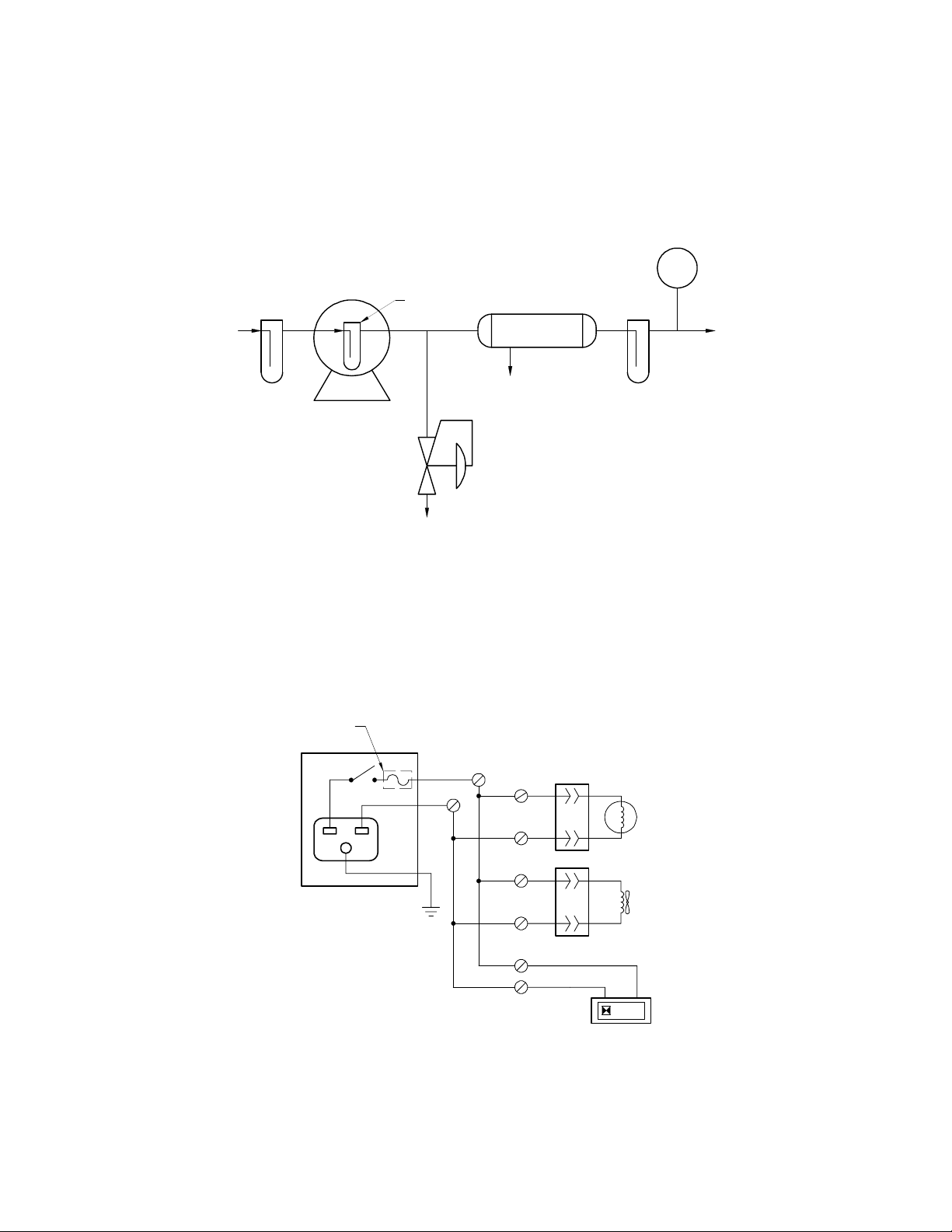
8.1 Pneumatic Schematic
BACK PRESSURE
REGULATOR VALVE
SET @ 170 PSIG
(REG)
COMPRESSOR
(COMP)
AIR
INTAKE
FILTER
(LF1)
MEMBRANE
AIR DRYER
(AD1)
FILTER
(LF2)
GAUGE
(G1)
OUTLET
1/4" FPT
PRESSURE
BLEED
SWEEP
FILTER
(LF3)
Figure 1-1
8.2 Electrical Schematic
123.4
POWER ENRTY
MODULE
(PEM)
COMPRESSOR
(COMP)
CIRCULATION
FAN
(CF1)
HOUR METER
(HM1)
LN
G
CN1
CN2
TB-1
TB-2
TB-3
TB-4
TB-5
TB-6
TB-7
TB-8
PIN1
PIN2
SLOW BLOW
10 AMP FUSE
(FS1)
Figure 1-2
Thunder Scientific Corporation ACS-1200 Air Compressor System 1-8
Document Number: ACS-1200.DOC - Edition 1 - July 2005

9 TROUBLESHOOTING GUIDE
Possible Reason No / Low High Excessive Over Won't
Pressure Pressure Noise Heating Start
Dirty Intake Filter X
Hose Leak X
Regulator Adjustment X X X
Worn or Damaged Compressor X X X
Worn or Damaged Fan X X
Safety Valve Leak X
Safety Valve "Popping Off" X X
Plugged Pressure Line X X
Low Voltage X X
Blown Fuse X X
Blocked Ventilation Opening X X X
High Outlet Pressure X
Overheating X X
10 PARTS LIST
Find # Qty Description Mfgr. Part Number
PEM 1 Power Entry Module Schurter KM01.1205.11
FS1 1 Fuse, 10 Amp Time Delay Littelfuse 218010
HM1 1 Hour Meter Curtis 700DR001048150D1002230A
COMP 1 Compressor, Air Gast 71R545-P315B-D401X
G1 1 Gauge, Pressure Ashcroft 20W1001TH01BXUC
REG 1 Regulator, Back Pressure Jordan JBP5S7A15
AD1 1 Air Dryer, Membrane Air Products PC1010-P1-3A-20
CF1 1 Fan, Circulation Comair Rotron 028245/MR2B3
LF1 1 Filter Element, Inlet Rietchle Thomas C87713
LF2 1 Filter Element, Outlet Wilkerson FRP-96-729
LF3 1 Filter Element, Interstage Norgren 665-75
Thunder Scientific Corporation ACS-1200 Air Compressor System 1-9
Document Number: ACS-1200.DOC - Edition 1 - July 2005
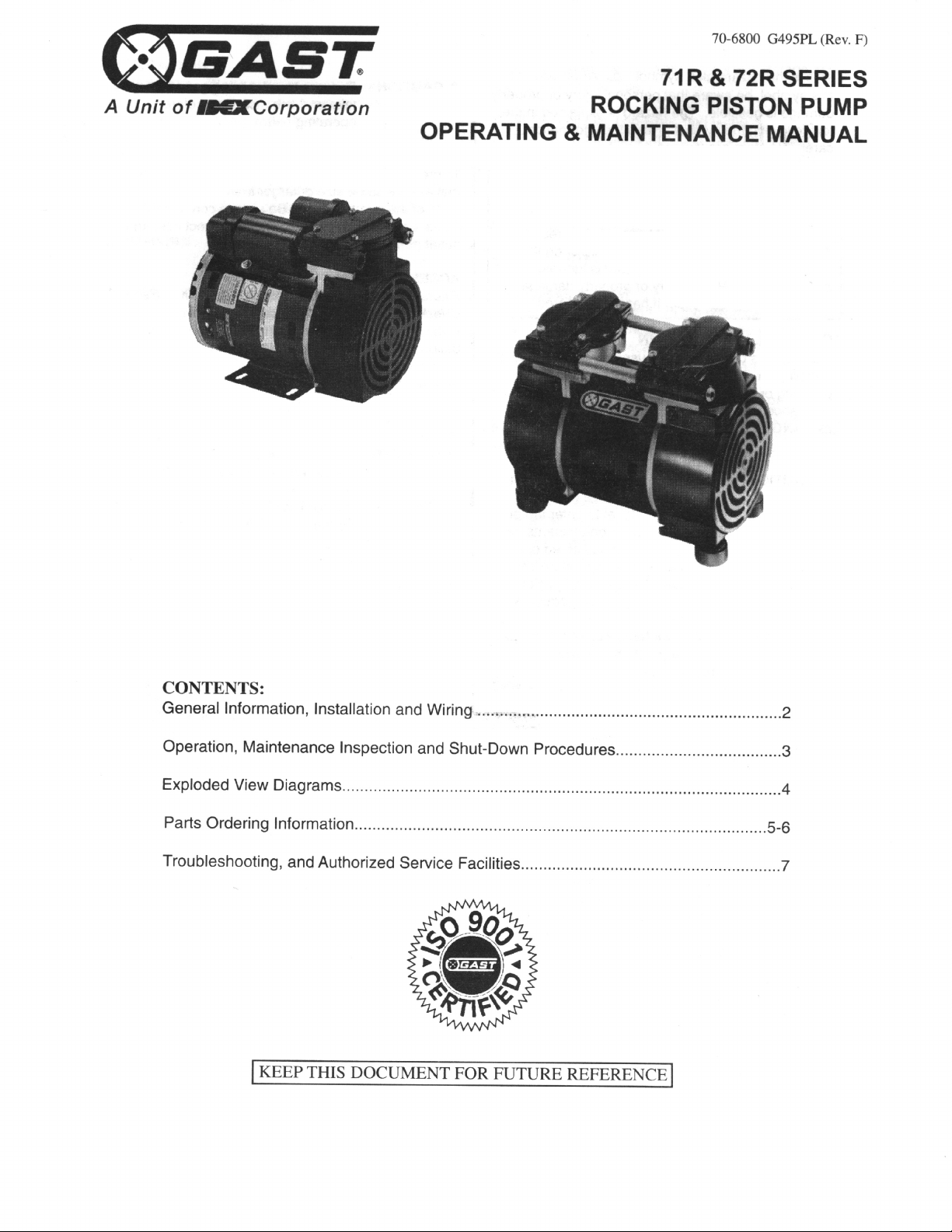
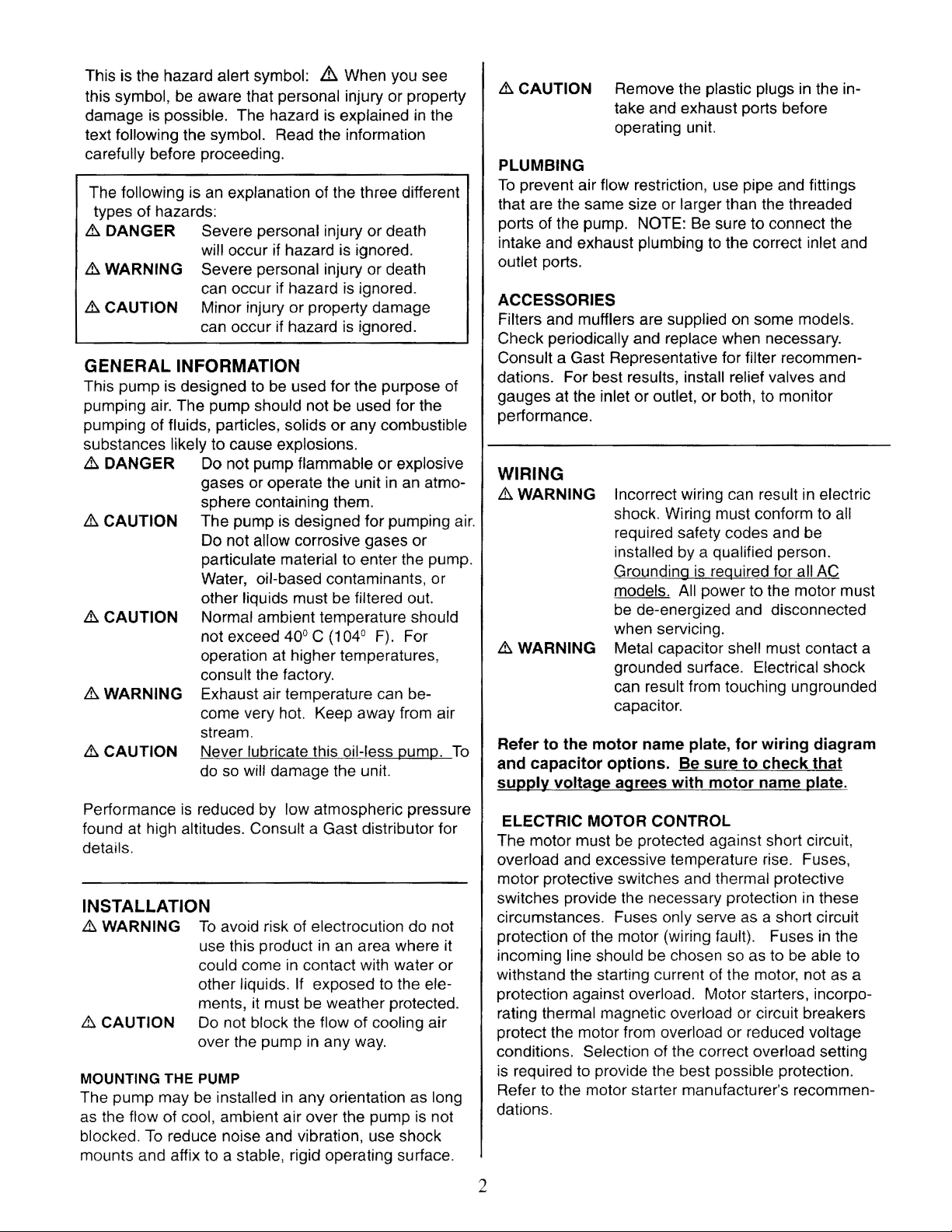

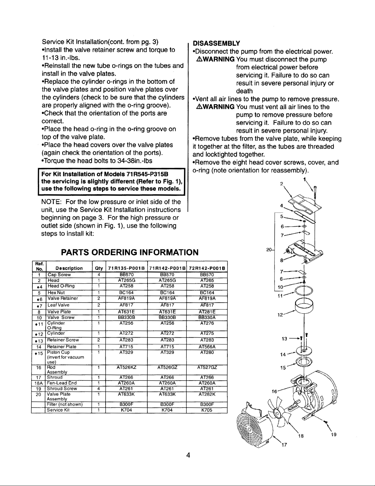
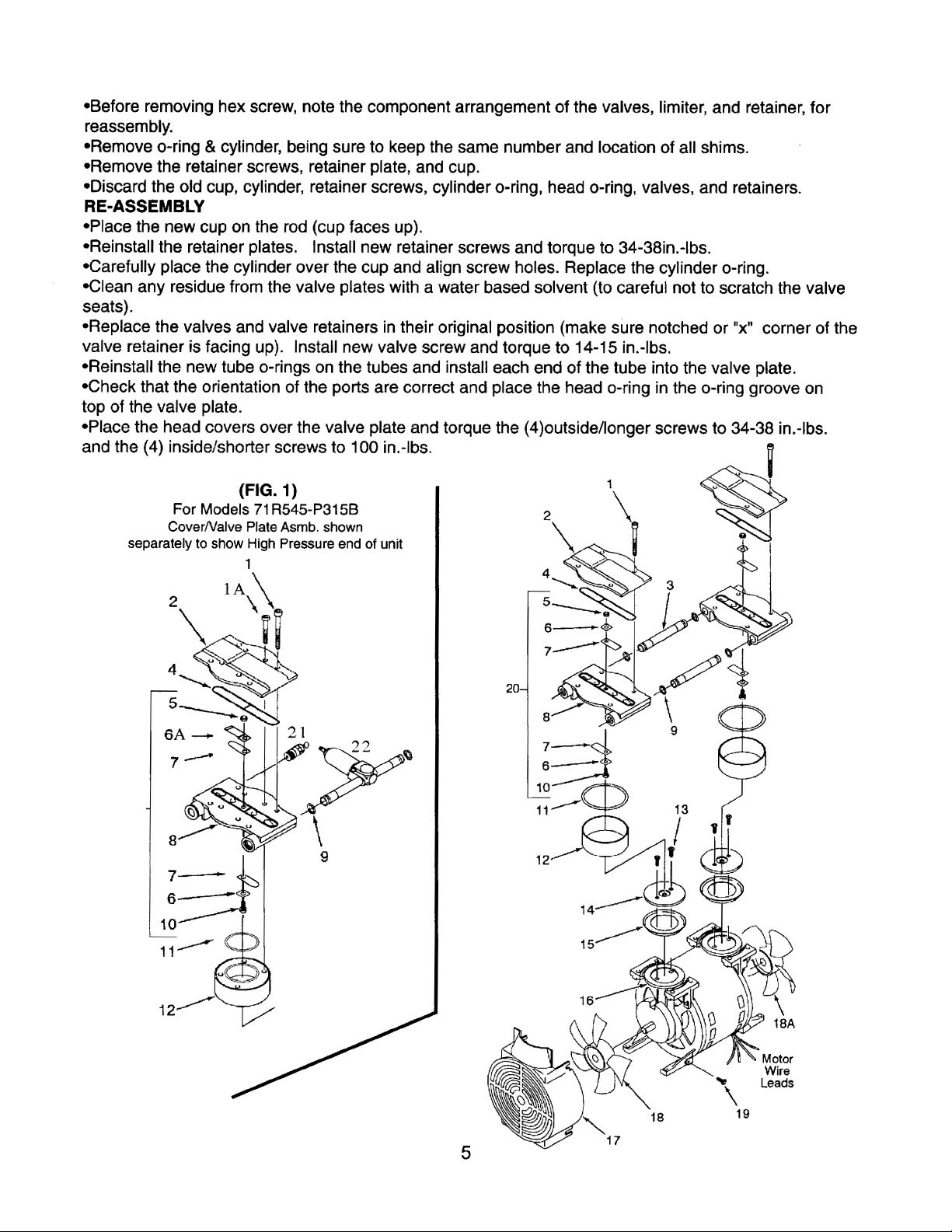


Table of contents
Popular Air Compressor manuals by other brands


California Air Tools
California Air Tools 20020AD-22060 owner's manual

Vector
Vector VEC270S owner's manual

GEA
GEA HG7 Assembly instructions

California Air Tools
California Air Tools 10020CHAD owner's manual

Eaton Compressor
Eaton Compressor Polar Air PRS0050001 operating instructions

Briggs & Stratton
Briggs & Stratton 203721GS Operator's manual


