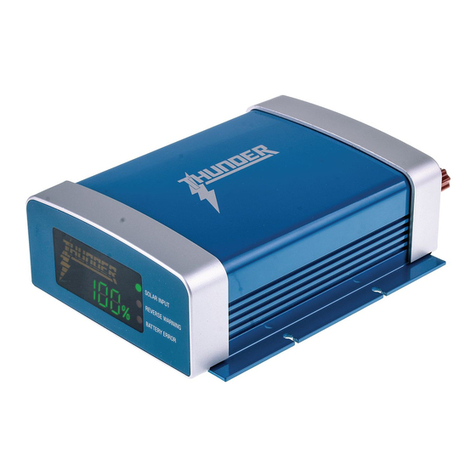
Thunder 8A User manual

1
For your personal safety read, understand and
follow the information provided in this instruction
manual & on the battery charger.
This automatic battery charger is a sophisticated
IP65 water-resistant 8 stage charger, utilising fully
automatic computer system control, designed to
charge most 12 Volt GEL, AGM, Lead Acid and
Calcium batteries.
CONGRATULATIONS ON
YOUR PURCHASE OF YOUR
THUNDER BATTERY CHARGER!

2
• Heavy duty design.
• Fully automatic 8 stage charging.
• Pulse mode technology that reduces oxidation, evens electrolyte consistency
and combats stratification in the battery, equating to longer battery life.
• IP65, CE, EMC, SAA and C-TICK Approved, making it ideal for automotive
and marine situations.
• Compatible with GEL, AGM, Calcium, Deep Cycle and conventional flooded
Lead Acid batteries.
• Internal charger temperature monitoring and power output control.
• Calcium charge map selected with push button and LED indicators.
• Charger selects correct charge map automatically for GEL, AGM,
Deep Cycle and conventional flooded Lead Acid batteries.
• LED display showing battery capacity status and warning indicators.
• Zero volt minimum battery start up - can charge a completely
discharged battery.
• Over charging, short circuit and over temperature protection.
• Reverse polarity protection with visual alerts.
• Permanent connection lead supplied with charger for vehicles that
require frequent charging such as classic cars, motorcycles marine craft
or heavy duty equipment.
FEATURES & BENEFITS
Features & Benefits

3
1. During the charging process, do not use a naked flame near a battery.
Batteries generate explosive gasses during the charging process that
may explode.
2. Never smoke or light cigarettes near a battery.
3. Do not place tools on top of a battery or allow tools to fall on the battery
to prevent the chance of a short circuit and sparks.
4. Always wear eye protection when charging a battery.
5. Ensure charging and testing is conducted in a well ventilated area.
6. Ensure the chargers ventilation holes are not obstructed. Inadequate
ventilation may over-heat the charger and cause in-efficient operation.
7. This battery charger is not intended for outdoor operation.
Do not expose it to moisture or extreme weather conditions.
8. If skin or clothing comes in contact with battery acid, flush the affected
area immediately with water. Seek medical attention if necessary.
9. The battery charger contains hazardous voltages.
There are no user serviceable components inside. If the AC supply cord is
damaged, in order to avoid a hazard it must be replaced by the manufacturer,
service agent or equally qualified person.
To avoid any personal injury, please read the following safety instructions. This battery charger is not intended for use by young children or infirm persons
without supervision.
NOTE:
The warnings, cautions and instructions detailed in this instruction manual cannot cover all possible conditions and situations that may occur.
Common sense and caution are factors which cannot be built into this product and must be supplied by the operator.
IMPORTANT SAFETY WARNINGS
FOR AUTOMOTIVE 12 VOLT USE ONLY, NOT TO BE USED WITH DRY CELL BATTERIES.
Important Safety Warnings

4Charging Instructions
CHARGING INSTRUCTIONS
SUITABLE FOR 12 VOLT VEHICLES
Connecting the charger to a battery in a vehicle:
The vehicle battery does not need to be disconnected or removed from the
vehicle to use this charger as long as the following instructions are followed:
Ensure the ignition and all of the accessories in the vehicle are switched off as
this will maximise the charge that your battery receives as well as minimising
any chance of damage occurring to the vehicle onboard electronics.
If accessories in the vehicle are left on and their power consumption exceeds
the output of the battery charger your battery can still discharge with the charger
connected and operating.
1. Inspect the electrolyte levels in the battery and top up if required.
2. Connect the red positive (+) lead of the battery charger to the
positive (+) post of the battery.
3. Connect the negative (-) lead of the battery charger to negative (-) post
of the battery.
4. Plug the battery charger into the mains power supply and switch
on power.
5. If you are charging a Calcium battery hold down the selector switch
for 5 seconds until the green LED lights up. The charge map for
Calcium batteries is now being used.
IMPORTANT: DO NOT USE THE CALCIUM FUNCTION ON ANY OTHER
TYPE OF BATTERY AS THIS COULD DAMAGE YOUR BATTERY.
6. The battery is fully charged when the THUNDER logo is fully lit and the
percentage reads 100%. This is the maintenance stage of the charger,
and it can be left connected in this stage indefinitely without damage to
the battery, making it ideal for winter maintenance or periods where the
vehicle is not going to be used for some time.
DISCONNECTING THE CHARGER FROM A BATTERY:
1. To avoid sparking, turn off and unplug the charger from the mains power
supply before making or breaking connection to the battery.
2. Remove the black negative (-) then the red positive (+) of the battery
charger from the battery or unplug the terminal connector lead.
3. Re-inspect the electrolyte levels in the battery and top up if required
(non maintenance free and non sealed battery types only).
REVERSE POLARITY PROTECTION:
When the battery charger has been connected to the battery in a reversed
polarity, the reverse warning indicator (orange LED display) will continually flash.
The charger will not supply any output power until a correct polarity connection
is made.
If the battery the charger is connected to is faulty the battery error indicator
(red led on display) will continually flash.

5
Explanation of Stages
EXPLANATION OF STAGES
This charger automatically employs an 8 stage charging program. These stages automatically switch from one to the next without any user input required.
• Desulphation
In this initial start up stage, a high frequency voltage pulse assists in
“waking up” a deeply discharged battery. This method of pulse charging can
also help reduce the build up of sulfate crystals that may have formed on the
battery plates during the time it was discharged. This stage will last as long as
it takes the battery to reach approximately 10 volts. If the connected battery is
only slightly discharged, this stage may only be activated for a short time
before automatically switching to the next soft start stage.
• Soft Start
After the battery is connected most conventional “Smart” battery chargers
will immediately apply a high charging voltage and current output. This
creates a large amount of gassing and heat generated by the battery that can
cause individual battery cell voltages becoming uneven. Uneven cell
voltages can cause individual cell overcharging or undercharging, lessening
the overall life span of your battery. The soft start function eliminates this by
starting the charge process slowly. Battery electrolyte and cell voltage is
given a chance to even out prior to the main bulk charging processes,
greatly increasing the batteries charging capability.
• Bulk
This is the main hard charging stage, where the charger will operate at its
maximum output current and voltage until it reaches the correct levels as
required from the selection made with the chemistry button (different
battery types require different charge levels). The charging period of this
stage is determined by the capacity and charge state of the connected
battery and will fluctuate between different battery types.
• Absorption
After the bulk stage, the charger will automatically begin to reduce its current
output whilst maintaining the required voltage (depending on the chemistry
of the battery). When the current reaches a pre-determined threshold level,
charging will halt allowing the next analysis stage to be performed.
• Analysis (Testing the battery whilst charging)
After the absorption stage, the battery charger will start the analysis stage
and will stop charging the battery for approximately one minute. At this
point, if the battery voltage drops too quickly past set parameters the battery
error indicator (red LED) will be flashing, your battery may be faulty. Please
see your local auto electrician to have your battery evaluated. If the battery
passes this test without any faults detected, it will then move to the boost
stage.
• Boost
After a successful result from the analysis stage, the charger will now
enter the Boost stage where voltage is increased to maximum and the
current is reduced to approximately 25% of the rated output. This stage
brings the battery safely up to a 100% fully charged state.
• Float
This stage provides a constant voltage to the battery compensating for
temperature and self-discharge of the battery.
• Maintenance
This stage evens out voltage between all cells and will maintain a constant
pulse voltage with a very small current. This stage will remain on indefinitely
whilst the battery is connected and is perfect for long term maintenance
for vehicles or stand-alone batteries that will not be used for long periods of
time such as winter storage. Keeping your battery on a maintenance charge
will ensure it is always 100% charged and in turn will reduce the chance of
sulfation, extending battery life and serviceability. During long term
maintenance, it is important to periodically check fluid levels in the battery
if it is NOT a sealed or maintenance free design.

6
SPECIFICATIONS
LED DISPLAY SCREEN OPTIONS:
1. If charging a Calcium battery push the selector button for 3 seconds
so the green Calcium LED is on.
2. Only use this function when charging a Calcium battery, using the
Calcium charge function on any other battery may cause damage.
3. If charging a GEL, AGM or standard Lead Acid battery simply connect and
forget as the charger will choose a suitable charge rate for that battery.
4. Charging voltage will display on screen at all times during the
charging process.
5. Battery capacity display will show 10% for each bar of the THUNDER logo.
When the THUNDER logo is illuminated the battery is fully charged (100%).
6. If reverse polarity connected, the orange LED on the display will flash.
7. The charger will not operate unless the charger is connected correctly.
Battery capacity: 15-150Ah and 200Ah for maintenance.
ONLY TO BE USED WITH 12V BATTERIES -
NEVER ATTEMPT TO RECHARGE DRY CELL BATTERIES.
Specifications
CHARGING VOLTAGES
GEL LEAD ACID / AGM CALCIUM
CHARGING STAGES 14.3 Volt 14.8 Volt 15.6 Volt
BOOST 14.8 Volt 15.2 Volt 16.2 Volt
FLOAT 13.3 Volt 13.7 Volt 13.7 Volt
SPECIFICATIONS
INPUT VOLTAGE 230VAC / 50HZ
TYPE 8 Stage Pulse
APPROVAL IP65, CE, EMC, SAA and C-TICK
SAFETY PROTECTION
Over charging, reverse polarity
(Flashing LED), short circuit and
over temperature
MINIMUM START VOLTAGE ≥0V
OPERATING TEMPERATURE -15°C - +50°C
MAXIMUM CHARGING CURRENT 8 Amps

7
Warranty Terms & Conditions
When you acquire or fit a Thunder product you have the peace of mind in knowing that it is backed by a comprehensive 12 month warranty
against defects in materials & workmanship. The Thunder warranty is provided in additional to any rights you may have under the
Australian Consumer Law.
All claims under this warranty should be made by returning the product to the place of purchase at your expense, with the detail of the fault,
proof of purchase & fitment details. If we determine that a Thunder product is defective in materials or workmanship during the warranty period,
we will either repair or replace the unit.
This warranty does not apply to failure or damage to a Thunder product caused by incorrect or faulty fitment, accidental or intentional damage,
failure of other products, incorrect application, incorrect voltage, environmental damage, operation of the product outside of its environmental
and technical specifications, or repair or modification carried out by anyone other than an authorised repairer.
Our goods come with guarantees that cannot be excluded under the Australian Consumer Law. You are entitled to a replacement or refund
for a major failure & compensation for any other reasonably foreseeable loss or damage. You are also entitled to have the goods repaired or
replaced if the goods fail to be of acceptable quality & the failure does not amount to a major failure.
WARRANTY TERMS & CONDITIONS

8
GPC Asia Pacific Pty Ltd
ABN 97 097 993 283
51-57 Qantas Drive
Brisbane Airport QLD 4007
AUSTRALIA
thunderauto.com.au // thunderauto.co.nz
This manual suits for next models
1
Table of contents
Other Thunder Batteries Charger manuals
