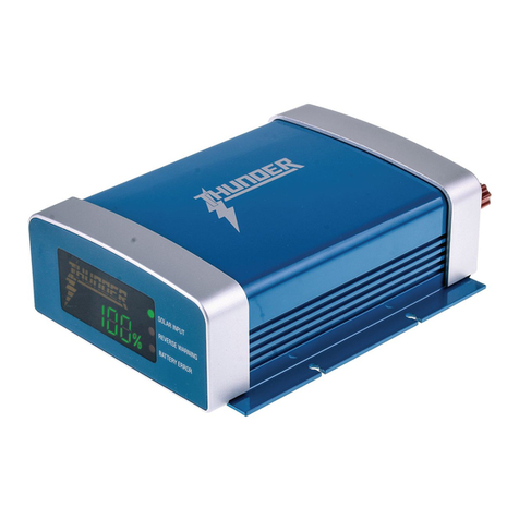
Thunder TDR02026 User manual

For your personal safety, read, understand and follow
the information provided in this instruction manual.
THANK YOU FOR CHOOSING
THE THUNDER BATTERY
MANAGEMENT SYSTEM

2
3. Features & Benefits
4. Installation
5. Operation
5. Charging Stages
7. LCD Display Operation
8. Display
9. Wiring
10. Specifications
11. Warranty Terms & Conditions
Copyright © 2020 GPC Asia Pacific Pty Ltd ABN 97 097 993 283
CONTENTS

3
FEATURES & BENEFITS
• Heavy duty aluminium housing.
• 8 Stage charging for 240VAC and DC-DC charging, when not in lithium mode.
• 3 stage charging for 240VAC, DC-DC and solar charging battery when in lithium mode.
• 30A 240V charging.
• 30A DC-DC charging.
• Solar input with MPPT regulated output (50V 500W max).
• 12-24V system input (12V output).
• 0-50° Operating Temperature.
• Internal charger temperature monitoring and power output control.
• Over charging, short circuit and over temperature protection.
• Output reverse polarity protection.
• Removable 3.5 inch Bluetooth colour LCD display with touch screen functionality.
• Automatically switches between AC, DC-DC and solar charging modes, depending on connected charging mode, Prioritises AC charging first, DC-DC second and solar third.
• Solar Panel charging will automatically charge 12V starting battery or auxiliary battery depending on which battery has lower voltage.
• Can charge Gel, Lead Acid, Calcium, AGM and Lithium batteries (Need to connect lithium charging wire to earth).
• Includes 200A External Shunt.

4
• Secure the charger and external shunt using the mounting tabs on the unit and shunt.
• Connect the wire from the main starting battery of the vehicle to the input red stud
on the rear of the TDR02026 charger using suitable cable (see specification table on
page 9), it is recommended to place a circuit breaker (50A minimum, not supplied)
in the main positive lead as close as possible to the starting battery.
• Connect the positive wire from the auxiliary battery to the output red stud on the
front of the TDR02026 charger, ensure the correct size cable is used to prevent any
voltage drop (see specification table on page 9).
• Connect the negative wire to the black negative stud on the front of the TDR02026,
to the negative terminal of the main battery (see specification table on page 9).
• The TDR02026 will work with even the newest computer-controlled alternators,
for installation into vehicles with variable voltage alternators, negative must be
connected to the vehicles earth terminal on the main battery.
• If connecting a solar panel, connect the positive from the panel to the solar input
stud on the rear of the TDR02026 and the negative of the panel to the main negative
stud on the front of the TDR02026 (see specification table on page 9).
• There is no need for an external regulator the TDR02026 has a built in MPPT
solar regulator.
• Connect the Shunt plug to the matching plug on the TDR02026, connect a wire
from the negative auxiliary battery terminal to the battery side of the shunt, connect
all loads you would like measured to the load side of the shunt.
• Check all connections are tight and secure.
• If charging a lithium battery, the Blue wire on the front of the TDR02026 will need to
be connected to battery earth (see specification table on page 9), *If not charging a
Lithium battery do not connect this wire.
• Once correctly installed the TDR02026 is a simple set and forget Battery
Management solution.
NOTE: Only connect this wire if charging a lithium battery pack as it will cause damage to
alternate battery packs.
• Fit the LCD display in your desired spot.
• Connect the red wire to battery or Ignition positive and the black wire to earth
from the display. There is a handy switch on the base to disable the display (see
specification table on page 9).
• Start the vehicle and let it idle, the charger will recognise that there is charge being
applied to the main starting battery. Once the main starting battery has reached
13.1V the charger will link and automatically begin to charge the auxiliary battery.
• The charger will continue to operate even after the vehicle has been switched off,
however once the main start battery falls below a loaded voltage of 12.2V the
charger will automatically shut down.
• The TDR02026 will prioritise the vehicle input over the solar input so while the
battery voltage is above 12.2V it will continue to charge, however once the main
battery has reached a loaded voltage of 12.2V and the charger switches off it will
look for a solar input.
• If the solar input is above 13.7V then the LCD display will move to Solar input to indicate
that the TDR02026 is now using the solar input to charge the auxiliary battery.
• Once the 240V circuit is live the TDR02026 will begin charging the batteries from
the 240V AC-DC 30A charger, once it has reached 100% the charger will move into
maintain mode monitoring the batteries and charging when needed.
WE RECOMMEND INSTALLATION BY A QUALIFIED AUTO ELECTRICIAN
INSTALLATION

5
• This product can be used as 240VAC charger for 12V batteries, or can be used as a DC-DC charger by installing the unit onto a vehicle and hard wiring the unit onto the starter battery
to charge a 12V auxiliary battery. The unit can also be used to connect solar panels and can charge either the 12V starter battery of a vehicle or the 12V auxiliary battery depending on
which battery has lower voltage.
The priority of charge for the TDR02026 is to prioritise 240VAC charge first, then DC-DC Vehicle charging, then Solar panel charging. This means that if the 240VAC plug is plugged in and
powered, while also having solar panel connected, the 240VAC charging mode will be prioritised, and solar panel charging will be disabled. If the vehicle is driving, and the DC-DC charging
is activated, the solar panel charging will be disabled. Solar panel charging will only occur if the 240VAC and DC-DC charging is not operational.
The unit can also charge lithium batteries, but the installer will need to connect the lithium charging blue wire to earth for the charging mode to change to lithium battery.
1. Analysis / Desulphation
A small voltage pulse is applied to the battery to ensure it can effectively and safely accept
a charge. Desulphation uses pulse reconditioning to gently remove any sulphation build
up on the battery plates and prevents oxidization. Stabilizes electrolyte consistency and
minimises the battery temperature rising while charging, recovers battery capacity and can
help extend battery life.
2. Soft Start
The soft start function improves the batteries charging capability, reduces gas and heat
build-up and can improve electrolyte consistency which can become uneven in the battery
cells from day to day use. A steadily increasing current is applied over a set time so as
not to initially overload the battery. This stage prepares the battery for the more intense
charging stages to follow.
3. Bulk charge
Maximum charge current is delivered to the battery to minimize charge times.
4. Absorption
Reduces the current supplied to the battery and ensures that the battery has been
completely charged without the risk of being overcharged.
5. Analysis – Testing the battery while charging
The charger shuts off power and measures voltage drop over a set time. If unacceptable
readings are measured this may indicate an internal short or other issue inside the battery.
• If the battery has a fault the charger will stop charge, the charger will cut output and not
continue to charge until it is either switched off, or the battery is removed. Faulty Battery
indicators on the screen will activate if the battery being charged is completely dead and
cannot be charged.
6. Boost/ equalisation charge
Once the battery is fully charged, the charger will equalize all of the battery cells by
providing a steady set voltage over a programmed period of time, at low current.
7. Float stage
After the boost stage, the current will drop to low amperage to maintain the battery in a
fully charged and ready to use state.
8. Maintenance charge
After float stage the voltage will maintain at a constant level with a small pulse frequency.
Current is dropped to a very low level.
AC AND DC-DC 8 STAGE
OPERATION
CHARGING STAGES
Table of contents
Other Thunder Batteries Charger manuals
