Thundercomm Thundersoft TurboX S625 User manual

Thundercomm
Thundersoft TurboX® S625
EVB User Guide
REVISION
PAGES
1.0
1of 29
STATE
TITLE
Released
Thundersoft TurboX® S625 EVB User Guide
Version
Date
Description
V1.0
2017-10-24
Initial Version
V2.0
2017-12-28
1, EVB board upgrade to V2.0.
2, Change extension interface pin 2 and 4 to EXT_IF_VIN_5V.
3, Add I2S D2 and D3 to extension interface pin 11 and 13.
4, Closed some known issues

2
Contents
1INTRODUCTION .................................................................................................................................................... 5
1.1 PURPOSE ............................................................................................................................................................. 5
1.2 SAFETY GUIDANCE .............................................................................................................................................. 5
2REFERENCES ......................................................................................................................................................... 6
2.1 REFERENCE DOCUMENTS ................................................................................................................................... 6
2.2 DEFINITION &ACRONYMS.................................................................................................................................... 6
3HARDWARE OVERVIEW ........................................................................................................................................ 7
3.1 OVERVIEW............................................................................................................................................................ 7
3.2 ELECTROSTATIC PROTECTION............................................................................................................................. 8
3.3 PACKAGE LIST...................................................................................................................................................... 8
4THUNDERSOFT TURBOX® S625 EVB ...................................................................................................................... 9
4.1 BLOCK DIAGRAM.................................................................................................................................................. 9
4.2 HARDWARE SPECIFICATION................................................................................................................................. 9
4.3INTERFACE MAP................................................................................................................................................. 11
4.3.1 Top View................................................................................................................................................... 11
4.3.2 Bottom View............................................................................................................................................. 12
4.4 BASIC APPLICATION ........................................................................................................................................... 13
4.5 DETAILED DESCRIPTION .................................................................................................................................... 14
4.5.1 12V DC Jack............................................................................................................................................ 14
4.5.2 Battery Connector................................................................................................................................... 14
4.5.3 POWER ON Key..................................................................................................................................... 15
4.5.4 Micro USB3.0........................................................................................................................................... 15
4.5.5 Debug UART Connector........................................................................................................................ 15
4.5.6 Force USB Boot Key .............................................................................................................................. 16
4.5.7 USB 3.0 TypeA Host Connector............................................................................................................ 16

3
4.5.8 HDMI OUT TypeA Connector................................................................................................................ 16
4.5.9 Ethernet Connector................................................................................................................................. 17
4.5.10 Volume Key.............................................................................................................................................. 17
4.5.11 TF Card connector.................................................................................................................................. 18
4.5.12 Speaker Connector................................................................................................................................. 18
4.5.13 3.5mm Audio Jack................................................................................................................................... 19
4.5.14 Touch Panel Connector.......................................................................................................................... 19
4.5.15 LCD Connector........................................................................................................................................ 20
4.5.16 Fan Connector......................................................................................................................................... 21
4.5.17 Extension Interface................................................................................................................................. 21
4.5.18 Camera Connector.................................................................................................................................. 22
4.5.19 DMIC......................................................................................................................................................... 23
4.5.20 Switch ....................................................................................................................................................... 24
4.5.21 LED ........................................................................................................................................................... 24
5OPERATION GUIDE...............................................................................................................................................25
5.1 HARDWARE PREPARATION................................................................................................................................. 25
5.1.1Config fastboot & adb tools ................................................................................................................... 25
5.2 POWER ON......................................................................................................................................................... 25
5.2.1 Power on with Key.................................................................................................................................. 25
5.2.2 Power on with USB................................................................................................................................. 25
5.3 POWER OFF....................................................................................................................................................... 26
5.4 RESET ................................................................................................................................................................ 26
5.4.1 Reset by Hard key .................................................................................................................................. 26
5.4.2 Reset by Command................................................................................................................................ 26
5.5 IMAGE UPGRADE................................................................................................................................................ 26
5.5.1 Firmware Programming.......................................................................................................................... 26
6FEATURES LIST AND KNOW ISSUES ......................................................................................................................28

4
6.1 FEATURES LIST.................................................................................................................................................. 28
6.2 KNOW ISSUES .................................................................................................................................................... 28
6.3 CLOSED ISSUES................................................................................................................................................. 28

5
1 Introduction
1.1 Purpose
This document describes the features on Thundersoft TurboX® S625 EVB, aims to guide the developer how to
design and verify their products based on Thundersoft TurboX® S625 module.
1.2 Safety Guidance
Caution: Electrostatic protection in use.
The EVB can be supplied by power adaptor. Required output of the power adaptor should be 12V,
currency is greater than or equal to 2A. Thundercomm supplied power adaptor is recommended.
The EVB can be supplied by battery. Required output of the battery is 3.8V.
Please do disconnect power supplier before plug in/out any extension boards or modules.

6
2 References
2.1 Reference Documents
Document
Thundersoft TurboX® S625 SOM Datasheet
Thundersoft TurboX® S625 Package List
Thundersoft TurboX® S625 CarrierBoard Part Reference
Table 2.1-1 Reference Documents
2.2 Definition & Acronyms
SOM
System on Module
EVB
Evaluation Verification Board
BT
Bluetooth
BLSP
Based low-speed peripheral
DSI
Display Serial Interface
CSI
Camera Serial Interface
DSP
Digital Signal Processor
GPIO
General-Purpose input/output
HDMI
High Definition Multimedia Interface
I2C
Inter-Integrated Circuit
I2S
Inter-IC Sound
ISP
Image Signal Processor
LAN
Local area network

7
UART
Universal Asynchronous Receiver/Transmitter
USB
Universal Serial Bus
WLAN
Wireless LAN
LED
Light-emitting diode
DC
Direct current
eMMC
Embedded Multi Media Card
Table 2.2-1 Definition & Acronyms
3 Hardware Overview
3.1 Overview
Thundersoft TurboX® S625 EVB is a powerful board, built with Qualcomm processors, high performance and
rich interfaces. It integrates Android OS, is suitable to evaluate, optimize, test and release intelligent
hardware products by developers, OEM, consumer businesses, hardware module producers, smart camera
producers, and etc.
Figure 3.1-1 Thundersoft TurboX® S625 EVB

8
3.2 Electrostatic Protection
There are many interfaces on the device, and frequent plug-in connections, so it is required to take proper
electrostatic protection during daily usage:
Utilize ESD table mat
Wear anti-static wrist strap or heel grounder
Note:
All of interfaces and buttons are all ESD, following standard Electromagnetic compatibility IEC61000-4-2.
3.3 Package List
Please refer to Thundersoft TurboX® S625 Package List.
9
4 Thundersoft TurboX® S625 EVB
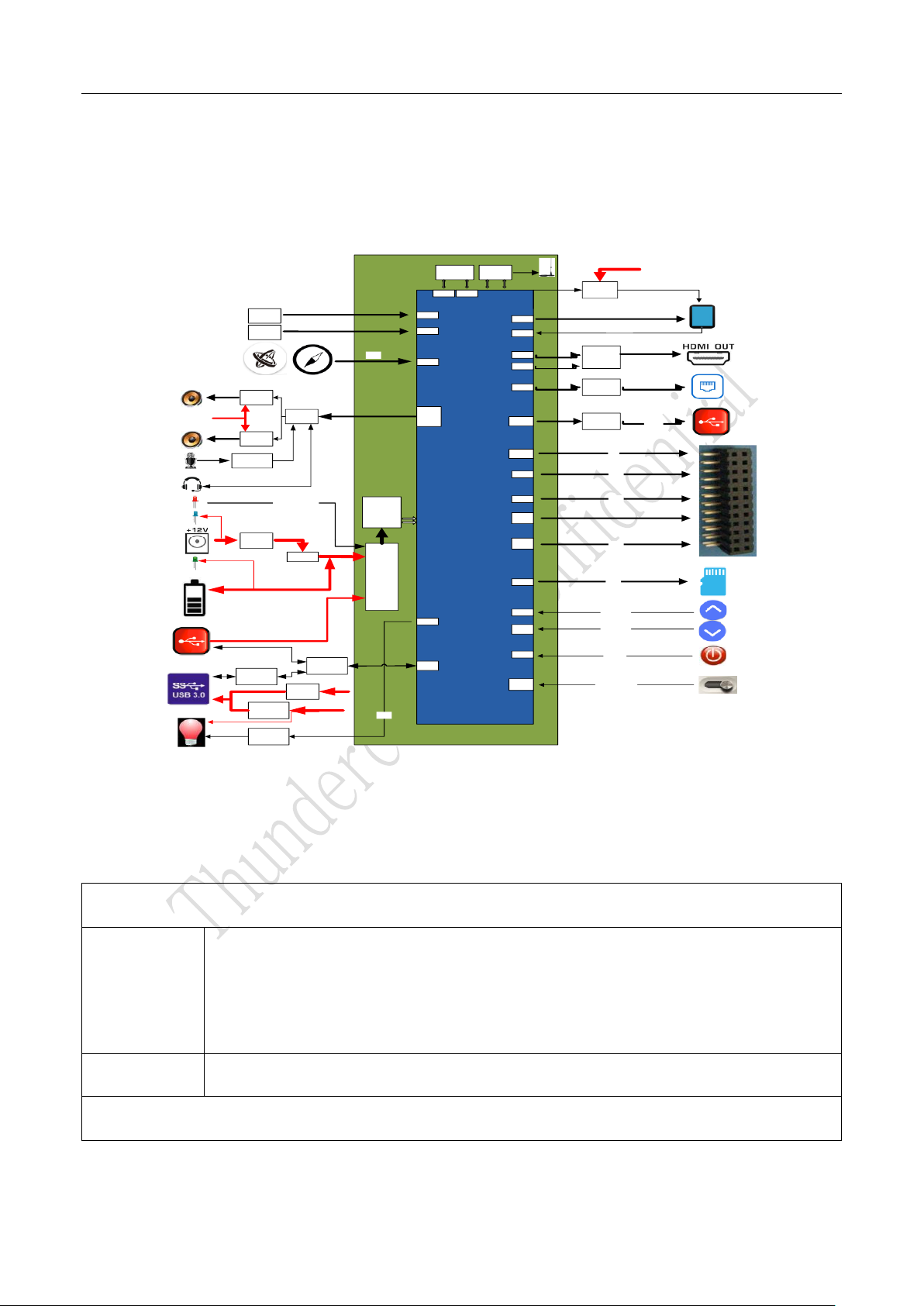
4.1 Block Diagram
APQ8053
eMCP
(2GB+16GB)
WIFI&BT
(wcn3680B)
PMI8952
PM8953
4*Dmics
Arry
(PDM IF)
CAM
(IMX214)
CAM
(IMX214)
LCM
backlight
(TPS61165)
TP I2C3
lpddr3 emmc
LT8912B
(mipi2hdmi)
KSZ8851SNL
(SPI2LAN)
HD3SS6126
(USB3.0
SPDT)
GPIO
I2C4
WSA8810
(audio PA)
SDIO
SY8104
(dcdc
VBUS
CYUSB3304
(USB3.0 HUB)
SN3193
(RGB driver)
I2C2
SY7215
(1.4A@5V)
Volume +
Volume -
On/off
CSI0
CSI1
BLSP4
BLSP2
USB3.0
phy
DSI0
DSI1
BLSP1
BLSP7
(SPI)
BLSP8
BLSP5
/BLSP6
SDIO
VOL UP
VOL
DOWN
ON/OFF
VBAT
VBAT
BLSP3
Charging led
Uart2
(blsp2)
Slimbus FT230XQ-R
(UART2USB)Debug
log
SPI
I2C8
I2C6
GPIOs
Dul Pmos
VBAT
SY8104
(dcdc
2.5A@5V) DC12 V
WSA8810
(audio PA)
VBAT WCD9335
(audio PA)
I2S1
I2S1
Auto On/off
CBL_PWR
(TBD)
Figure 4.1-1 Block Diagram
4.2 Hardware Specification
Processor
CPU
ARM Cortex-A53 microprocessor cores at 2.2 GHz
64-bit processor;
2.2 GHz: Octa-core: one quad with 1 MB L2 cache + one quad with 512 KB L2 cache;
Primary boot processor
DSP
Hexagon v56 16 KB/16 KB/512 KB ,850MHz
Memory
10
System
memory
16Gb, non PoP memory LPDDR3;32-bit wide; up to 933Mhz;
16GB,eMMC5.1;
Multimedia
MIPI_DSI
FHD (1920 × 1200) 60 fps; 16/18/24 bpp RGB;
MIPI DSI four-lane DSI D-PHY 1.1;
HDMI out
HDMI1.4 standard
1080p 60 fps
Camera
interfaces
Dual 14-bit ISP; 13MP and 13MP;24MP at 30fps ZSL with dual-ISP;13MP 30fps ZSL with
single ISP;
Support two 4-lane MIPI_CSI D-PHY 1.2;2.1Gbps per lane;
Pixel manipulations, camera modes, image effects, and postprocessing techniques,
including defective pixel correction
Sensor
Compass
3-axis magnetometer, 16-bit data out, Sensitivity: 0.15 μT/LSB
A+G
Combines a 3-axis gyroscope, 3-axis accelerometer, and a Digital Motion Processor
Connectivity
USB
3x USB3.0 type A host
1x MicroB USB3.0
1x Micro USB2.0(UART Log Output)
Ethernet
SPI to LAN
1x 10BASE-T
IEEE 802.3/802.3u Standards
SDIO
1x TF card
HDMI
1x HDMI OUT
Other IO
1x SPI
2x I2C
1x UART
Power
DC-Jack
1x 12V DC in
Battery in
1x Wafer-6Pin (>3.6v <4.2v)
Audio
11
Audio
1x 3.5mm HP jack (CTIA)
1x DMIC Extended Interface (support up to 4 DMICs)
4x DMIC (on board)
2x Class-D Smart Speaker (up to 8Ω@2W)
Key
key
1x power on
2x volume
1x force USB boot
Others
SW support
Android 7
Operating
temperature
-10℃- 55℃
Table 4.2-1 Hardware Specification
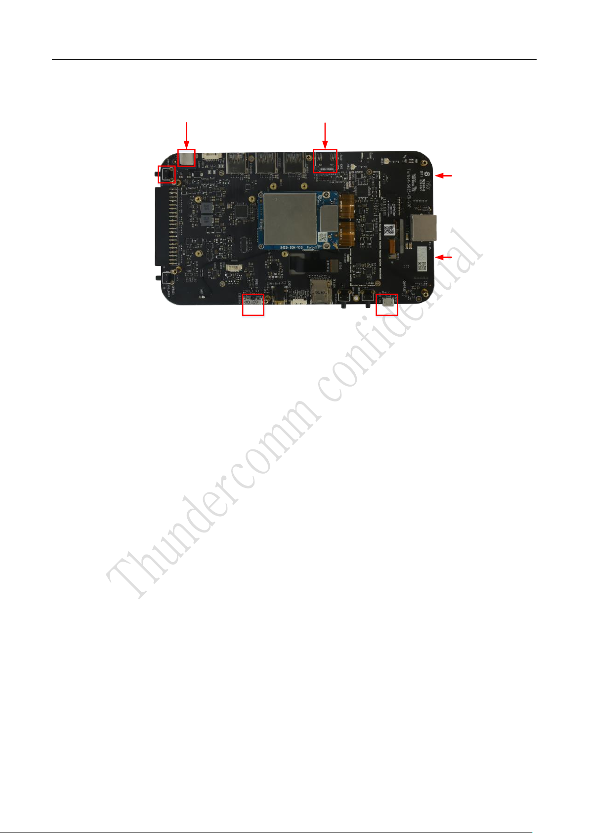
4.3 Interface Map
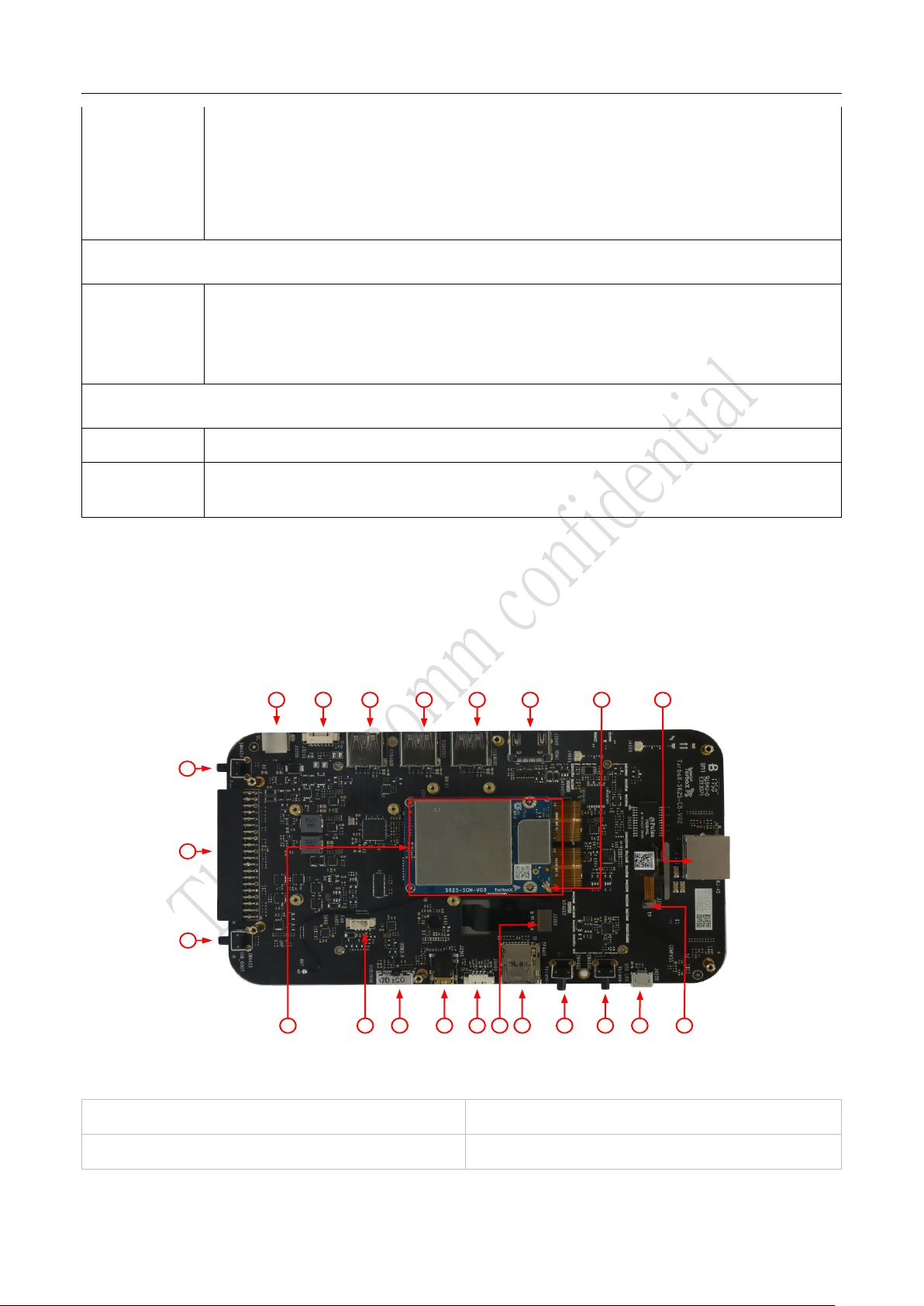
4.3.1 Top View
3
4
5 6 7 8 9 10 12
13141517182122
11
20 191
2
16
Figure 4.3-1 Thundersoft TurboX® S625 EVB Top View
1. Thundersoft TurboX® S625 SOM
2. Force USB Boot Key
3. General purpose header
4. POWER ON Key

12
5. 12V DC Jack
6.Battery connector
7. USB 3.0 Type A connector 1
8. USB 3.0 TypeA connector 2
9.USB 3.0 Type A connector 3
10. HDMI OUT TypeA connector
11. WLAN ext. ant. connector
12. 10Base/100Base Ethernet connector
13. Touch Panel connector
14.Debug UART connector
15. Volume up Key
16. Volume down or Reset Key
17. TF Card connector
18. LCD connector
19. Speakers connector
20. 3.5mm CTIA Header Audio Jack
21. Micro B USB3.0 connector
22. Fan connector
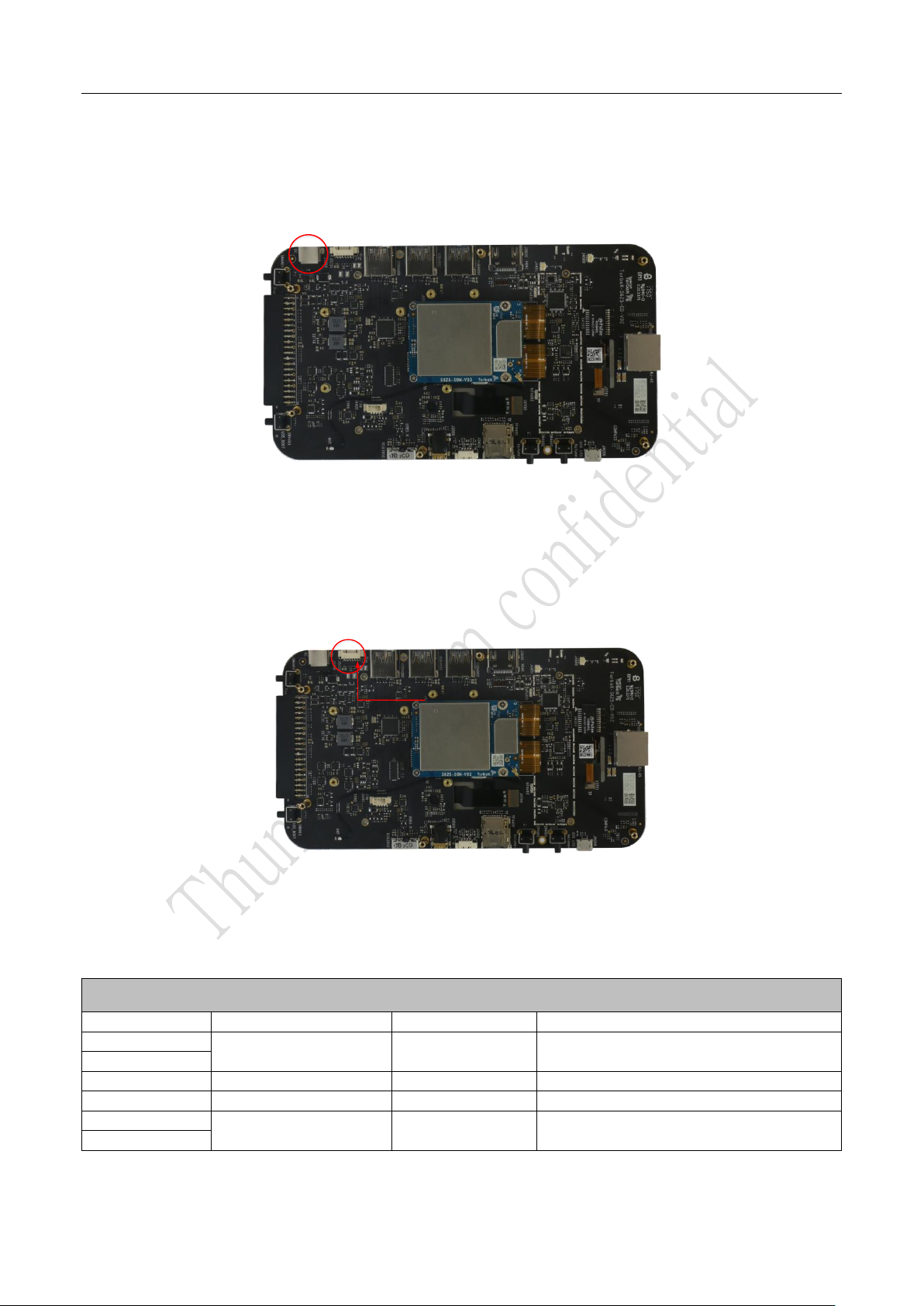
4.3.2 Bottom View
33
34
23 24 25 26 27
2829303132
Figure 4.3-2 Thundersoft TurboX® S625 EVB Bottom View
23. Switch for Power on mode
24. Status LDE
25. DMIC 1
26. DMIC 2
27. Camera CSI 1 connector
28. Camera CSI 0 connector
29. DMIC 3
30. DMIC 4
31. Charge LED
32. USB HUB LED
33. 4.1V LED
34. 12V LED
13
4.4 Basic Application
Power Adapter HDMI
USB
ON
Key
Camera
Connector in
back side
UART
Camera
Connector in
back side
Figure 4.4-1 Thundersoft TurboX® S625 EVB
Quick Start:
Remove Thundersoft TurboX® S625 EVB board carefully from the anti-static bag.
Assemble IMX214 Camera to the corresponding connector as show below.
Connect Thundersoft TurboX® S625 EVB to Display with HDMI.
Connect 12V, 2.0A Power Adapter to the Thundersoft TurboX® S625 EVB.
Press power button for 4 seconds, the board will begin to boot-up automatically.
Connect USB or UART to debug if needed.
14
4.5 Detailed Description
4.5.1 12V DC Jack
For convenient usage, 12V DC power adapter is provided in default package list. Battery & 12V power
adaptor can be used independently; when both are connected, the EVB will choose 12V adaptor and cut-off
battery power supplying. At the same time, system will switch to adaptor mode and cut-off charging.
4.5.2 Battery Connector
Pin 1
Support 3.8V battery with embedded thermal detecting. The connector part number is
WF12-062S3R/WAFER. PINs definition.
Battery Interface
PINs
Signal
IO Level
Description
1
-VBAT_CON
GND
Power supply negative
2
3
BAT_CON_ID
Battery ID
4
BAT_THERM
Battery thermal detecting
5
+VBAT_CON
3.6V-4.2V
Power supply positive
6
Table 4.5-1 Battery Interface Definition

15
4.5.3 POWER ON Key
Press this Key for 4 seconds, the system will boot-up automatically.
4.5.4 Micro USB3.0
The S625 EVB utilizes Micro USB3.0 interface by default, the major functions list below:
Software debugging /downloading and transmitting data by connecting with PC
Supporting USB3.0 and compatible with USB2.0
4.5.5 Debug UART Connector
The S625 EVB output log information with this interface, and internal USB converted to UART, so you can use
the universal USB cable.

16
4.5.6 Force USB Boot Key
When press this button and NO/OFF key, before insert the battery or 12v power adapter, the system enters
the force download mode (QFILE), which can be downloaded using the QFILE tool, but this is not
recommended.
4.5.7 USB 3.0 TypeA Host Connector
The EVB integrates USB3.0 HUB, complies with USB 3.0 specification version 1.0. Which supports the host
mode only. There are three USB 3.0 typeA interfaces, and the maximum output current 2A at the same time.
Notes: when the MicroB USB is using, the USB HUB cannot be used.
4.5.8 HDMI OUT TypeA Connector
The S625 EVB integrates MIPI DSI to HDMI bridge, complies with D-PHY1.1 and DSI1.02 . Support HDMI1.4

17
standard.
There are HDMI type A interface, and up to 60Hz 1080p 8-bit HDMI output.
4.5.9 Ethernet Connector
There are LAN interface, the S625 EVB integrates SPI to LAN Bridge.
4.5.10 Volume Key
Volume up
Volume down & Reset
There are volume keys. The user can generate a mandatory reset by long key pressing volume down key over
15s.

18
4.5.11 TF Card connector
Volume upVolume down & Reset
There are Push–Push micro SD card connector. Its supports SD 3.0.
4.5.12 Speaker Connector
Pin 1
There are speaker connector. The connector part number is WF12-042S3R/WAFER .
The S625 EVB integrates audio code WCD9335 and stereo speaker PA WSA8810. It is up to 8Ω@2W output.
Speaker connector
PINs
Signal
Type
Description
1
SPK_R_OUT_M
Right channel output
Right speaker negative output
2
SPK_R_OUT_P
Right speaker positive output
3
SPK_L_OUT_M
Left channel output
Left speaker negative output
4
SPK_L_OUT_P
Left speaker positive output
Table 4.5-3 Speaker Interface Definition

19
4.5.13 3.5mm Audio Jack
Volume upVolume down & Reset
There are 3.5mm audio headset connector. CTIA standard interface.
4.5.14 Touch Panel Connector
Pin 1
Pin 10
The S625 EVB has touch panel interface, the B to B connector part number is ASE5S1010. I2C signal pull up
on EVB board.
Touch panel connector
PINs
Signal
Voltag
e
Type
Description
2
TP_VDD_2V8
2.8 V
channe
l
output
PO
TP analog power output, max current 150 mA
3
TP_IO_1V8
1.8V
PO
TP IO power output, max current 100 mA
4
BLSP3_SPI3_SDA_CS_TP
1.8V
D
TP control interface I2C serial data
5
BLSP3_SPI3_SCL_CLK_TP
1.8V
C
TP control interface I2C serial clock
6
BLSP3_SPI3_MISO_TP_INT
DI
TP control interface I2C interrupt
7
BLSP3_SPI3_MOSI_TP_RST
DO
TP control interface reset output
1, 10
GND
-
-
GND
8, 9
NC
-
-
NC
Table of contents


