TIC SDR-OMNI User manual

SDR-OMNI
AVIONICS TEST SET
USER MANUAL
Revision B, 21 Februar 2023
Tel-Instrument Electronics Corp.
One Branca Road
East Rutherford, NJ 0707
(201) 99 -1600
www.telinstrument.com
2021-CLS-TIC-0001

NOTICE:
The information contained in this manual is subject to change without notice.
Tel-Instrument Electronics Cor . makes no warranty of any kind to this material, nor shall be liable including but
not limited to, errors contained herein or for incidental or consequential damages in connection with the
furnishings, erformance, or use of this material.
COPYRIGHT NOTICE
© 2022 Tel-Instrument Electronics Cor .
Re roduction of this ublication or any ortion thereof by any means without the ex ress written ermission of
Tel-Instrument Electronics Cor . is rohibited. For further information, contact the Customer Su ort Manager,
One Branca Road, East Rutherford, NJ 07073. (201) 993-1600.

SDR-OMNI Avionics Test Set User Manual
Revision B 21 February 202 Page i
TABLE OF CONTENTS
Warranty ..................................................................................................................................................................... 2
Warnings................................................................................................................................................................. 4
Cautions.................................................................................................................................................................. 4
Notes ...................................................................................................................................................................... 4
Cha ter 1 Introduction ................................................................................................................................................ 6
1.1
Sco e ......................................................................................................................................................... 6
1.2
Features ..................................................................................................................................................... 6
1.3
Com liance ................................................................................................................................................ 6
Cha ter 2 Pre aration for Use ................................................................................................................................... 7
2.1
Un acking .................................................................................................................................................. 7
2.2
Accessories Provided ................................................................................................................................. 7
2.3
Battery ...................................................................................................................................................... 19
Cha ter 3 SDR-OMNI Overview .............................................................................................................................. 20
3.1
Controls .................................................................................................................................................... 20
3.2
Indicators and Connectors ....................................................................................................................... 21
Cha ter 4 Powering ON and Initial Setu ................................................................................................................ 23
4.1
Power On ................................................................................................................................................. 23
4.2
Power OFF ............................................................................................................................................... 23
4.3
Home Menu .............................................................................................................................................. 24
4.4
Global System Settings ............................................................................................................................ 24
4.5
Charging the Battery ................................................................................................................................ 27
4.6
Retrieving and rinting test re orts .......................................................................................................... 28
Cha ter 5 Avionics Testing using the SDR-OMNI ................................................................................................... 29
5.1
Testing ATC Trans onders ...................................................................................................................... 29
5.2
Testing 1090 MHz (Mode S) ADS-B OUT ............................................................................................... 44
5.3
Testing 978 MHz UAT ADS-B OUT ......................................................................................................... 49
5.4
Testing 978 MHz UAT ADS-B IN and FIS-B ............................................................................................ 53
5.5
Testing ACAS/TCAS Systems ................................................................................................................. 54
5.6
Testing ILS Systems ................................................................................................................................ 54
5.7
Testing VOR Systems .............................................................................................................................. 64
5.8
Testing DME Systems .............................................................................................................................. 68
5.9
Testing ELT Systems ............................................................................................................................... 70
5.10
Testing HF/VHF/UHF COMM Radio Systems ......................................................................................... 70
5.11
Testing SELCAL Systems ........................................................................................................................ 70
5.12
Testing Audio Intercom Systems ............................................................................................................. 70

User Manual SDR-OMNI Avionics Test Set
Page ii 21 February 202 Revision B
Cha ter 6 Cable & Antenna Testing Using the SDR-OMNI ..................................................................................... 74
6.1
VSWR/Distance-to-Fault Calibration ........................................................................................................ 74
6.2
VSWR Measurement ............................................................................................................................... 75
6.3
Distance to Fault (DTF) Measurement ..................................................................................................... 77
6.4
Cable Loss Testing................................................................................................................................... 80
Cha ter 7 Analog Radio Testing .............................................................................................................................. 83
Cha ter 8 SDR-OMNI System Menu ....................................................................................................................... 92
APPENDIX A SDR-OMNI SPECIFICATIONS ..................................................................................................... 93
APPENDIX B Acronyms and Abbreviations ....................................................................................................... 104
APPENDIX C Navigation System Princi les .......................................................................................................... 2
Instrument Landing System (ILS) ........................................................................................................................... 2
VHF Omnidirectional Range (VOR) ....................................................................................................................... 6

User Manual SDR-OMNI Avionics Test Set
Page 2 21 February 202 Revision B
WARRANTY
The Tel-Instrument Electronics Cor . warrants that each roduct Tel-Instrument Electronics Cor . manufactures
is free from defective material and workmanshi for a eriod of two (2) years subject to the following terms and
conditions. Tel-Instrument Electronics Cor . will remedy any such warranted defect subject to the following:
• This warranty requires the unit to be delivered by the owner to Tel-Instrument Electronics Cor . intact for
examination, with all trans ortation charges re aid to the factory, within two (2) years from the date of sale to
original urchaser. Tel-Instrument Electronics Cor . will solely determine when such defect exists.
• This warranty does not extend to any of Tel-Instrument Electronics Cor . roducts which have been subject to
misuse, neglect, accident, im ro er installation, or used in violation of o erating instructions. This warranty
does not extend to units which have been re aired, calibrated, or altered in any way by a facility that is not
a roved, in writing, by Tel-Instrument Electronics Cor . to erform such work. This warranty does not a ly
to any roduct where the seals or serial number thereof has been removed, defaced, or changed, nor to
accessories not of Tel-Instrument Electronics Cor . manufacturing.
• This warranty is in lieu of all other warranties ex ressed or im lied and all such other warranties are hereby
ex ressly excluded. No re resentative or erson is authorized to assume for Tel-Instrument Electronics Cor .
any other liability or warranty in connection with the sale of Tel-Instrument Electronics Cor . roducts.
• This warranty does not cover or include batteries (batteries have a se arate 90-day warranty).
• Additional information regarding the a lications and maintenance of this equi ment will be available from
time to time.
Obtaining Warranty Service
If the SDR-OMNI requires service or re air under the warranty, follow these ste s to ensure ro er handling:
NOTE
The SDR-OMNI must be returned in its original shi ing container. If the
original shi ing container is not available, inform Customer Su ort of this
when contacting them.
1. Contact Tel-Instrument Electronics Cor . Customer Su ort using the contact information below. Customer
Su ort will review the matter and, if validated, Return Material Authorization (RMA) number and form.
• +1 (201) 933-1600 (tele hone)
• +1 (201) 933-7340 (fax)
• https://www.telinstrument.com
2. Pack the SDR-OMNI in accordance with Packing and Shipping for Warranty Service.
Packing and Shipping for Warranty Service
Before shi ing the SDR-OMNI for warranty service, ensure that:
• You have an RMA number and com leted form from Tel-Instrument Electronics Cor . Customer Service.
• You have the original shi ing container. If you do not have the original shi ing container, contact Tel-
Instrument Electronics Cor . Customer Service.
• You have aid the freight charges to shi the SDR-OMNI. Freight charges for shi ing the roduct to Tel-
Instrument Electronics Cor . are the res onsibility of the owner. However, Tel-Instrument Electronics Cor .
will ay the return shi ing charges if the roblem is determined to be covered under the warranty.

SDR-OMNI Avionics Test Set User Manual
Revision B 21 February 202 Page
CAUTION
DO NOT shi the SDR-OMNI without acking it in a shi ing container.
Shi ing it without a shi ing container may damage the SDR-OMNI.
NOTE
DO NOT shi any SDR-OMNI units before contacting Tel-Instrument
Electronics Cor . Customer Service.
DO NOT return any roduct without receiving an RMA number and form from
Tel-Instrument Electronics Cor . Customer Service.
To ensure rom t tracking and handling, the SDR-OMNI must be returned
with the com leted RMA form.
The SDR-OMNI must be returned in its original shi ing container. If the
original shi ing container is not available, contact Customer Service.
1. Wra the SDR-OMNI in bubble sheeting or lastic wra .
2. Place the SDR-OMNI into its original ackaging material and shi ing container.
3. Place the RMA form on to of the SDR-OMNI unit inside the shi ing container before sealing the shi ing
container.
4. Provide the following information either in or written on the shi ing container:
• The assigned RMA number written in bold letters on the outside of the shi ing container.
• Model, Serial Number, and s ecific details about the roblem.
• Point of contact (POC) name, return address, tele hone number, and email address.
5. Use acking ta e and seal all seams. If an industrial box sta ler is used, be sure the sta les do not rotrude
through the box to revent injury to ersonnel and damage to the equi ment.
6. Firmly affix the shi ing label and shi the SDR-OMNI to the following address:
Tel-Instrument Electronics Cor .
One Branca Road
East Rutherford, NJ 07073
(201) 993-1600
Attn: Re air De artment
SAFETY PRECAUTIONS
The following are general safety recautions that are not related to a articular test or rocedure. These are
recommended rocedures that all ersonnel must a ly during o eration and maintenance. The o erator must
have general knowledge of electrical theory and the dangers associated with it.
1. Before erforming any series of tests, thoroughly read and understand all rocedures before erforming them.
2. The various SDR-OMNI connectors, switches, and controls can be located by referring to Cha ter 3 ( age
20).
User Manual SDR-OMNI Avionics Test Set
Page 4 21 February 202 Revision B
3. Take the time to learn the ro er o eration and function of the SDR-OMNI. Com lete knowledge of the Test
Set and its ca abilities greatly reduces the time it takes to com lete the tests.
4. Pay articular attention to WARNINGS, CAUTIONS, and NOTES and that may accom any some test and
o erational rocedures.
5. Observe all standard safety rocedures when working with live voltages. The otential for electric shock
exists any time the SDR-OMNI is removed from its case.
6. DO NOT service or adjust the unit alone. Always be in the resence of another erson when working with live
voltages.
7. Thoroughly ins ect the equi ment and the local area for otential hazards. Loose clothing and jewelry should
be removed anytime the test set is being utilized or serviced.
8. Be familiar with general first aid rocedures and Cardio ulmonary Resuscitation (CPR).
9. Ensure the test equi ment and tools you use are in good o erational condition and not damaged in any way.
10. Use only a roved re lacement arts. Failure to use factory a roved arts may cause damage to ersonnel;
the test set, and ossibly void the warranty.
WARNINGS
WARNING
An o erating rocedure or ractice that, if not correctly followed, could result in
death or ersonal injury.
CAUTIONS
CAUTION
An o erational rocedure or ractice that, if not followed correctly, can result in
damage to or destruction of equi ment.
NOTES
NOTE
An o erating rocedure or condition that requires em hasis.
ELECTROSTATIC DISCHARGE (ESD)
The SDR-OMNI internal arts are ESD sensitive. An ESD may damage integrated circuits or semiconductors
located within the SDR-OMNI. Only qualified ersonnel should service the SDR-OMNI to revent damage. While
erforming test or maintenance, users must adhere to the following guidelines avoid ESD. These guidelines are
meant only as a reminder; users must consult local directives and follow standard o erating rocedures before
servicing or re airing the SDR-OMNI.
SDR-OMNI Avionics Test Set User Manual
Revision B 21 February 202 Page 5
• Wear a ro erly grounded wrist stra and remain in contact with an a roved grounding oint.
• Do not touch the connector ins or back lanes of ESD Sensitive circuits or arts.
• Ensure soldering irons are grounded before use.
• Do not remove any com onents or disconnect any connectors located in the SDR-OMNI with the ower “ON”.
• Pro erly ground all test equi ment being used. Refer to the test equi ment o erating manual for information.
• Place all removed com onents or arts in or on an a roved conductive ackage.
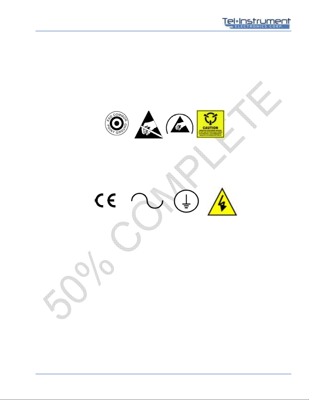
Most ESD devices or circuits and common oints are readily identified using several different methods. Below are
some exam les. See Figure 1 for exam le ESD label.
Figure 1. Example ESD Labels
The Euro ean Conformity (CE) (International Electric Commission (IEC)) marking symbols may be used in
different locations throughout the manual and are also located on and in the SDR-OMNI. Observe these warnings
and markings and follow standard electrical safety anytime you use live circuits. See Figure 2 for exam le
markings.
Figure 2. Example CE Markings
2021-CLS-TIC-0002
2021
-
CLS
-
TIC
-
0003

User Manual SDR-OMNI Avionics Test Set
Page 6 21 February 202 Revision B
CHAPTER 1 INTRODUCTION
1.1 SCOPE
This manual is intended to familiarize the user with the o erating rocedures necessary to ro erly use the SDR-
OMNI Avionics Test Set.
1.2 FEATURES
The SDR-OMNI is a lightweight, software-defined radio frequency (RF) test set for testing RF avionics in the 200
kilohertz (kHz) to 1.6 gigahertz (GHz) range. The SDR-OMNI is designed to test all of the basic navigation and
communications avionics functions common to modern civil and commercial aircraft, with rovisions for certain
military avionics test requirements.
It uses software defined signal rocessing to test com lex avionics navigations and communication signals.
The SDR-OMNI can be owered by either battery or AC ada ter. The SDR-OMNI includes a lithium-ion (Li-Ion)
battery that lasts 6 hours with continuous o eration or 24 hours on a 20% duty cycle. The SDR-OMNI also
includes an AC ada ter (100-240 Volts AC (VAC), 47-63 hertz (Hz)) that can ower the device and charge the
battery.
1. COMPLIANCE
This Product Meets or Exceeds the essential requirements of a licable Euro ean Directives as follows:
• EN 55022, B
• EN 61000-4-2, L2&3, B
• EN 61000-4-4, L2&3, B
• EN 61000-3-2, A
• EN 61000-4-3, L3, A
• EN 61000-4-6, L3, A

SDR-OMNI Avionics Test Set User Manual
Revision B 21 February 202 Page 7
CHAPTER 2 PREPARATION FOR USE
This section contains all necessary information on the initial un acking, ins ection, and setu of the SDR-OMNI.
Each SDR-OMNI has already undergone a com rehensive series of tests, full calibration, and Quality Assurance
checks before shi ment from Tel-Instrument Electronics Cor .
2.1 UNPACKING
1. After receiving the SDR-OMNI, ins ect the shi ing container for damage. Note any damage in case the
SDR-OMNI unit is also damaged.
2. Remove the SDR-OMNI from the shi ing container and ackaging material. Retain the shi ing container
and ackaging material for future shi ment or storage.
WARNING
DO NOT use a damaged SDR-OMNI. Using a damaged SDR-OMNI may
cause death or serious injury.
3. Ins ect the SDR-OMNI for damage to casing, connectors, switches, buttons, and dis lay screen. If damage is
found, DO NOT use the SDR-OMNI and contact Tel-Instrument Electronics Cor . Customer Service in
accordance with the Warranty. Make sure to inform Customer Service if the shi ing container was also
damaged.
4. Verify that all the accessory items listed in Table 2-1 were received.
2.2 ACCESSORIES PROVIDED
Table 2-1 Accessories Included with the SDR-OMNI Avionics Test Set
Descri tion TIC Part Number Quantity
Transit Case, Rugged 64030103 1
AC Power Ada ter/DC Charger (& AC Power Cord) 88000183 / 74000002 1 ea
L-Band Directional Antenna 40030046 1
Telesco ic Antenna 40030023 1
GPS Antenna 40030036 1
Wi-Fi Antenna 40030035 1
VSWR Return Loss Bridge 40200231 1
VSWR O en/Short Calibration Load 31020162 1
Kickstand Mount 88000185 1
Headset 75011002 1
TAP-OMNI Antenna Cou ler 90000150 1

User Manual SDR-OMNI Avionics Test Set
Page 8 21 February 202 Revision B
TAP-OMNI Whi Antenna Ada ter 54000044 1
10 meter Antenna Cou ler Cable 75010601 1
3 meter Direct Connect Cable 75010605 1
VSWR Bridge Connect Cables, 12 in (BNC-male to N-male) 75010600 2
Insertion Loss Calibration Cable, 12 in (BNC-male to BNC-male) 75010599 1
USB Ada ter Cable (A-male to Micro B-male) 75010598 1
USB Ada ter Cable (A-female to Micro B-male) 75010603 1
Aircraft Radio Audio Test Cable – civil 75010582 1
Aircraft Radio Audio Test Cable – military U-93A/U 75010604 1
Audio Port Ada ter Cable 75010591 1
CD-ROM – Manual & Download Utility Program 90008147 1
RF Ada ter Kit
Ada ter, TNC-female to BNC-male
Ada ter, N-male to TNC-female
Ada ter, N-male to BNC-female
48040171
48040178
48040167
1
1
1
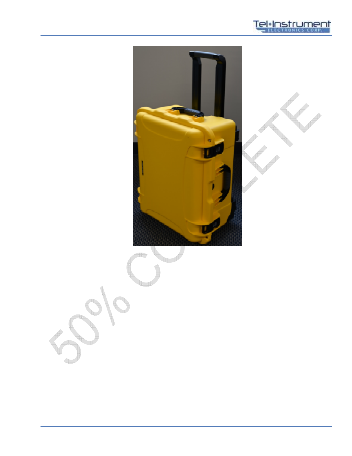
2.2.1 Transit Case
The Transit Case (Figure 2-1) safely stores the SDR-OMNI and its accessories while they are not in use. The
Transit Case can be carried using the carrying handles, or the Transit Case can be rolled using the two wheels
and extendable handle. The Transit Case can be secured shut with two latches.
Additionally, four metal grommets can be used to secure the Transit Case shut with zi ties or locks (not
included). The Transit Case cover has a rubber gasket to revent water from entering the Transit Case. The
Transit Case has a foam lining and a tray insert to organize and rotect the SDR-OMNI and its accessories.
SDR-OMNI Avionics Test Set User Manual
Revision B 21 February 202 Page 9
Figure 2-1. Transit Case
2021
-
CLS
-
TIC
-
0020

User Manual SDR-OMNI Avionics Test Set
Page 10 21 February 202 Revision B
2.2.2 AC Power Adapter/DC Charger
The AC Power Ada ter/DC Charger (24 Vdc) charges the battery and su lies ower to the unit for o eration.
See ( age 3) for ower s ecifications.
Figure 2-2. AC Power Adapter/DC Charger
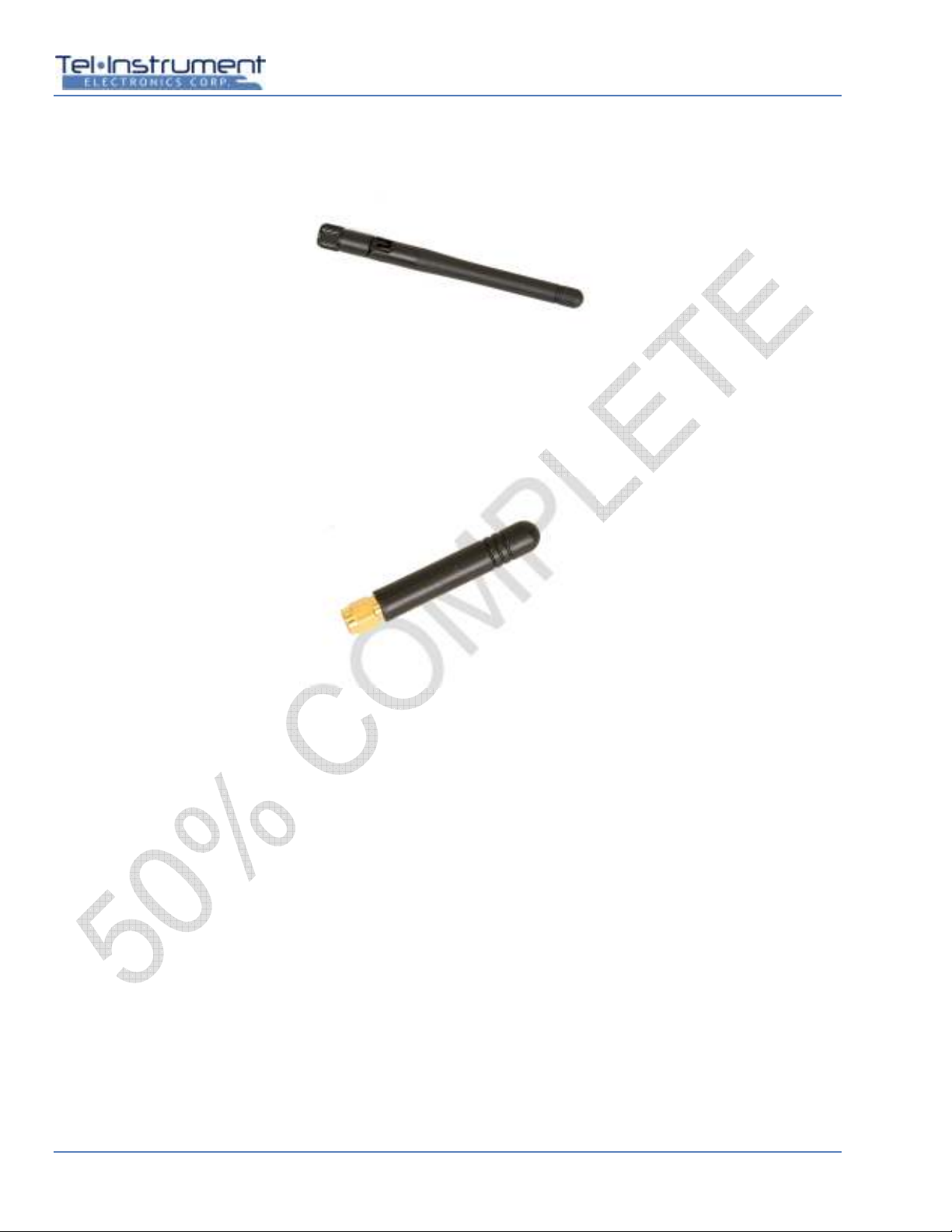
2.2.3 Telescopic Antenna
Most HF/VHU/UHF radio checks will be erformed over-the-air using the su lied Telesco ic Antenna (Figure
2-3). The length of the antenna should be adjusted for the wavelength of the frequency band being tested (refer to
Table 2-2 and Table 2-3 ).
Many basic functional tests (such as Very High Frequency (VHF) Omnidirectional Radio (VOR), Instrument
Landing System (ILS) Localizer (LOC), Glideslo e (GS), and Marker Beacon (MB)), Emergency Locator
Transmitter (ELT), Selective Calling (SELCAL), and Communication (COMM) tests) can be erformed by a single
o erator from the cock it. The Telesco ic Antenna can be extended out of the assenger door or the ilot’s
window. Otherwise, the SDR-OMNI should be laced 10 to 30 feet (3 to 9 meters) from the unit under test (UUT)
antenna with an unobstructed line-of-sight.
Hangars, ram equi ment, and other aircraft may interfere with test signals. If unex ected test results are
observed, first attem t to move the SDR-OMNI to a location that could minimize multi- ath interference and
retest.
Figure 2-3. Telescopic Antenna
2021
-
CLS
-
TIC
-
0052
2021
-
CLS
-
TIC
-
0021
SDR-OMNI Avionics Test Set User Manual
Revision B 21 February 202 Page 11
Table 2-2 NAV Frequencies
FUNCTION TESTED ANTENNA LENGTH
MB (75.0 MHz) Fully Extended
VOR (108.00-117.95 MHz) 28.5 inches (72 cm)
LOC (108.10 – 111.95 MHz) 28.5 inches (72 cm)
GS (329.15 – 335.00 MHz) 9.5 inches (24 cm)
COMM Frequencies
FREQUENCY TESTED ANTENNA LENGTH
HF 29 – 88 MHz Fully Extended
VHF 108-118 MHz 28.5 inches (72 cm)
VHF 118-156 MHz 24 inches (61 cm)
VHF 156-174 MHz 9.5 inches (24 cm)
UHF 225 – 299 MHz 11 inches (28 cm)
UHF 300 – 400 MHz Base section only
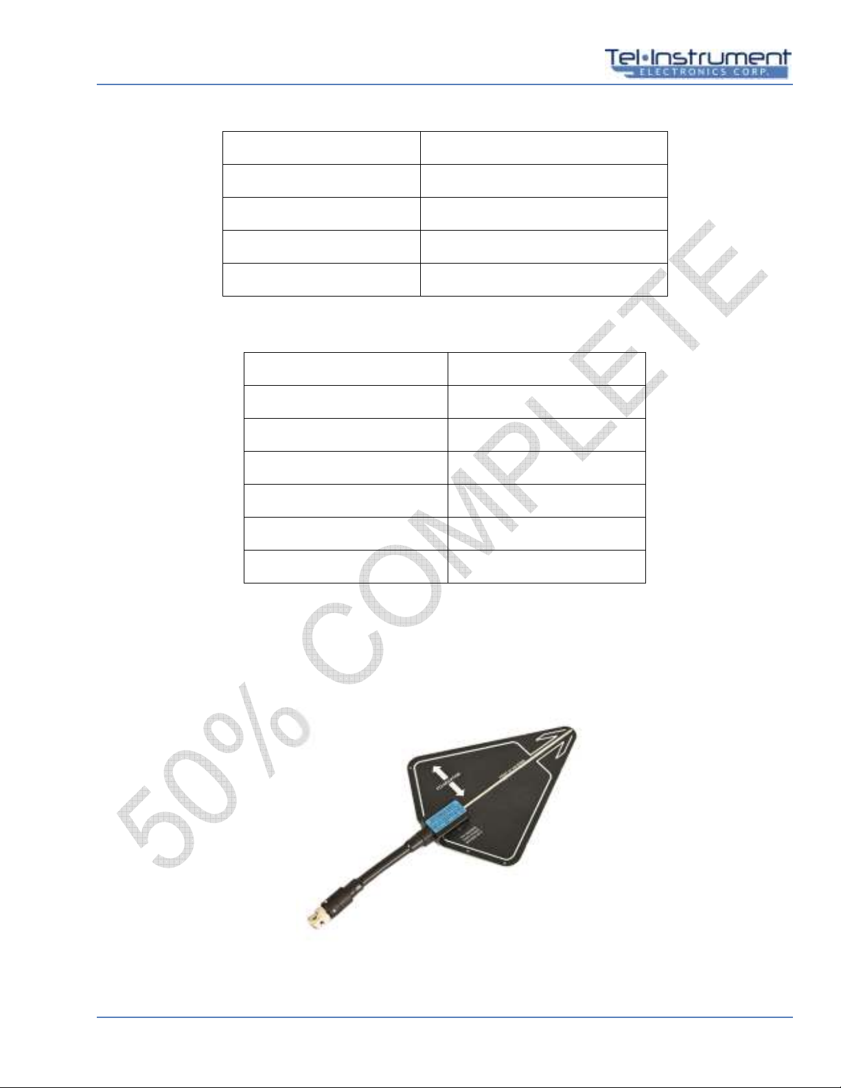
2.2.4 L-Band Directional Antenna
The Directional Antenna (Figure 2-4) has a flexible neck and guide arrows to ro erly osition the antenna for L-
Band (Trans onder, TCAS, UAT) testing. Note that the antenna is vertically olarized, so the flat ortion of the
antenna should be oriented vertically when ointing at the aircraft’s ATC, TCAS, or DME antenna.
Figure 2-4. L-Band Directional Antenna
User Manual SDR-OMNI Avionics Test Set
Page 12 21 February 202 Revision B
2.2.5 i-Fi Antenna
The Wi-Fi Antenna (Figure 2-5) enables the SDR-OMNI to connect to a wireless network.
Figure 2-5. Wi-Fi Antenna
2.2.6 GPS Antenna
The GPS Antenna (Figure 2-6) enables the SDR-OMNI’s internal GPS receiver to receive GPS signals.
Figure 2-6. GPS Antenna
SDR-OMNI Avionics Test Set User Manual
Revision B 21 February 202 Page 1
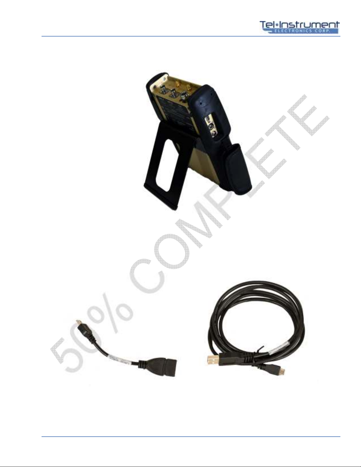
2.2.7 Kickstand Mount
The Kickstand (Figure 2-7) su orts the SDR-OMNI so it can be laced in a comfortable osition for viewing.
Figure 2-7. Kickstand Mount
2.2.8 Micro USB adapter CableS
Two USD Ada ter cables are rovided. The USB-A to Micro B Cable (Figure 2-8) enables the SDR-OMNI to
connect to a ersonal com uter (PC) for u loading new rogram file into the SDR-OMNI and downloading test
re orts. A second cable, USB-A to Micro B-female cable is also rovided, for use if necessary.
Figure 2-8. Micro USB Adapter Cables
2021
-
CLS
-
TIC
-
0025

User Manual SDR-OMNI Avionics Test Set
Page 14 21 February 202 Revision B
2.2.9 VS R Return loss Bridge
The VSWR Return Loss Bridge (Figure 2-9) is used for making VSWR and Distance-to-Fault (DTF)
measurements using the SDR-OMNI.
Figure 2-9. VSWR Return Loss Bridge
2.2.10 VS R Open/Short Calibration Load
This device is used during the VSWR calibration rocess. One side is an o en circuit and the other side is a
short circuit. Refer to VSWR o eration in Cha ter 6
Figure 2-10 VSWR Open/Short Calibration Load
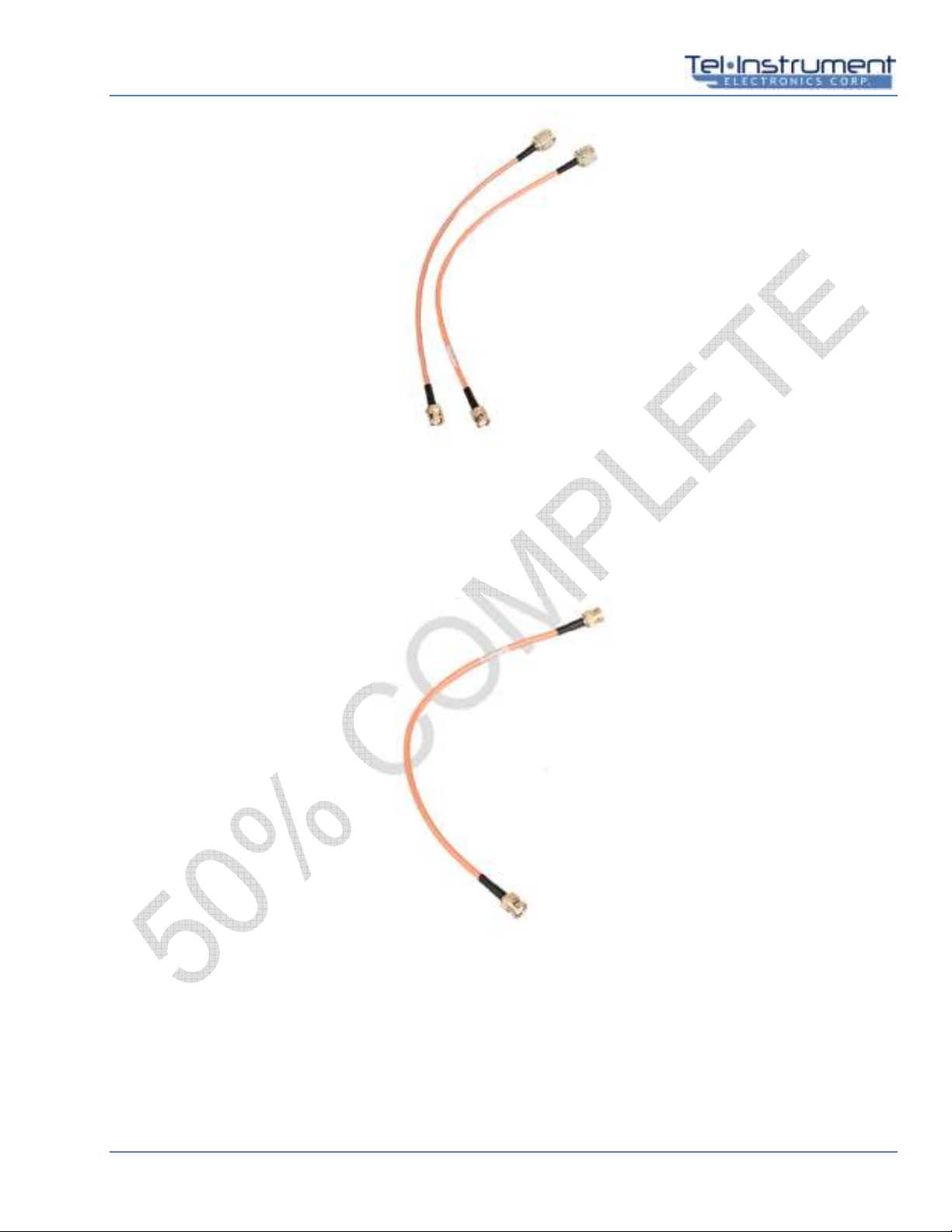
2.2.11 VS R Bridge Connect Cables
Two identical 12 inch cables are rovided to connect the SDR-OMNI to the INPUT and OUTPUT orts on the
VSWR Return Loss Bridge. They have a BNC-male on one end and an N-male on the other end.
SDR-OMNI Avionics Test Set User Manual
Revision B 21 February 202 Page 15
Figure 2-11 VSWR Bridge Connect Cables
2.2.12 Insertion Loss Calibration Cable
This is a 12 inch BNC-male to BNC-male cable that connect the ANT-A and ANT-B orts on the SDR-OMNI
during the Cable Loss calibration rocedure.
Figure 2-12 Insertion Loss Calibration Cable
2.2.13 Headset
The Headset (13) can be used to listen to HF, VHF, or UHF COMM radio voice transmissions from an aircraft and
for transmitting voice from the SDR-OMNI to the aircraft COMM radio.

User Manual SDR-OMNI Avionics Test Set
Page 16 21 February 202 Revision B
Figure 2-13 Headset
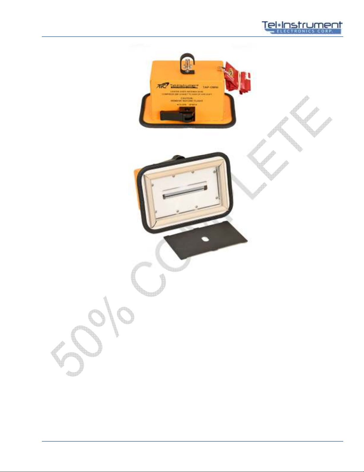
2.2.14 TAP-OMNI Antenna Coupler & hip Antenna Adapter
The TAP-OMNI Antenna Cou ler (Figure 2-14) is designed to fit over a sharkfin style ATC Trans onder antenna
to rovide a high level of RF attenuation and revent the testing of the aircraft trans onder/ADS-B device from
interfering with ATC o erations. It also enables the test o erator to obtain much more accurate and re eatable
ower and sensitivity readings, as it greatly reduces multi- ath and uncertainty when com ared to over-the-air
testing with a directional antenna.
A Whi Antenna Ada ter is also included in the SDR-OMNI kit. It is used when testing aircraft that have a short
L-Band di ole trans onder antenna. The whi ada ter fits into the bottom of the TAP-OMNI, which is then
laced over the di ole antenna and clam ed into lace. The whi ada ter serves to center the di ole antenna in
the TAP-OMNI so that the o erator obtains reliable test results.
SDR-OMNI Avionics Test Set User Manual
Revision B 21 February 202 Page 17
Figure 2-14 TAP-OMNI Antenna Coupler & Whip Antenna Adapter
2.2.15 3 meter Direct Connect & 10 Meter Antenna Coupler Connect Cables
Two RG-400 RF cables with TNC-male connectors on each end are rovided. The 10 meter cable connects the
SDR-OMNI to the TAP-OMNI Antenna Cou ler. The 3 meter cable is used to connect the SDR-OMNI directly to
a trans onder, by assing the antenna. Both cables have the cable loss, in dB, marked on the cables. These
values will be entered into the SDR-OMNI during the initial setu rocedure.
Other manuals for SDR-OMNI
1
Table of contents
Other TIC Test Equipment manuals


