5.2. The tester has self-diagnostic function, information as following chart:
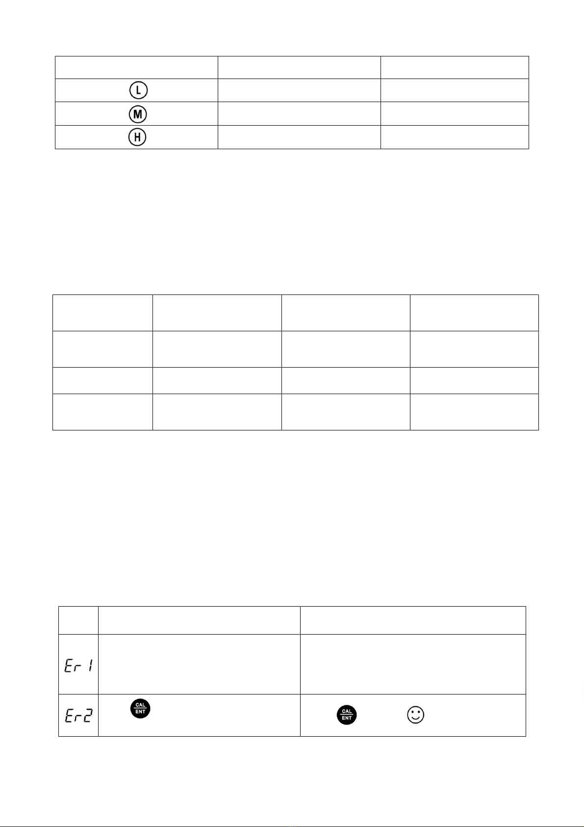
Self-diagnostic information
Wrong pH buffer solution or the recognition
range of calibration solution exceeds standard.
1. Check whether pH buffer solution is correct.
2. Check whether the probe is damaged.
Press key when measuring value is not
stable during measurement.
Press key when icon appears.
6. Conductivity Calibration
6.1. Press key to switch to conductivity measurement mode. Rinse the probe in pure water
and dry it.
6.2. Fill certain amount (about half volume of the calibration bottle) of 1413μS and 12.88mS
conductivity standard solution in separate calibration bottles.
6.3. Long press key to enter calibration mode, short press to exit.
6.4. Dip the probe in 1413μS conductivity standard solution and stir gently, leave to
Stabilize (LCD display as shown in the picture on the right), Short press key
to complete 1-point calibration, The tester then returns to measurement mode and
indication icon will appears on the LCD.
6.5. For multi-point calibration (either 2 or 3 point), rinse the probe in clean water and repeat step
6.4 using 84uS standard solution and / or 12.88mS standard solution. After completion of each
point, the calibration icons (for 84uS) and (for 12.88mS) will appear on the LCD near
the .
7. Conductivity Measurement
7.1. Press key to turn on the tester. Rinse the probe in pure water and dry it. Dip the probe in
sample solution, stir gently, leave to Stabilize, Get reading after LCD displays .
7.2. Press key to switch between →→→
8. Notes
8.1. The tester uses 84μS, 1413μS and 12.88mS conductivity standard solution. User can conduct 2
or 3point calibration. Refer to the chart as following. Generally, calibrating the tester with 1413μS
conductivity standard solution alone will meet the testing requirement.