TIC TR-220 User manual
TR-220
MULTIFUNCTION TEST SET
Transponder, TCAS, DME, TIS, and ADS-B
Test Set
Operational Manual
Software Revision 3.40 and Later
REVISION
A B C D E F G H J K L M N
P R S T U V W X Y Z
09 May 2007
Tel-Instrument Electronics Corp
728 Garden Street
Carlstadt, NJ 07072
(201) 933-1600
www.telinstrument.com

Leading the AVIONICS TEST industry into the 21st Century!
NOTICE:
The information contained in this manual is subject to change without notice.
Tel-Instrument Electronics Corp. makes no warranty of any kind to this material,
nor shall be liable including but not limited to, errors contained herein or for
incidental or consequential damages in connection with the furnishings,
performance, or use of this material.
Chapter I – Introduction
Chapter II – Preparation for Use and Operation
Chapter III – Theory of Operation
Chapter IV – General Maintenance and Servicing Procedures
Chapter V – Schematics
Chapter VI – Illustrated Parts Catalog
COPYRIGHT NOTICE
© 2007 Tel-Instrument Electronics Corp
Reproduction of this publication or any portion thereof by any means without the
express written permission of Tel-Instrument Electronics Corp. is prohibited. For
further information, contact the Customer Support Manager, 728 Garden Street,
Carlstadt, NJ 07072. (201) 933-1600
PART NUMBER VOLUMES INCLUDED CHAPTERS INCLUDED
90008088-1 VOLUME 1 CHAPTERS I&II
90008088-2 VOLUMES 1&2 CHAPTERS I-VI

Safety Precautions
The following are general safety precautions that are not related to a particular test or procedure.
These are recommended procedures that all personnel must apply during many phases of
operation and maintenance. It is assumed that the operator has general knowledge of electrical
theory and the dangers associated with it.
1. When performing any of the preceding; thoroughly read and understand all
procedures before actually performing them.
2. The various front panel connectors, switches, and controls specified can be
located by referring to Figure 2-1 on page 2-3.
3. Take the time to learn the proper operation and function of the Test Set as
outlined in Chapters 1, 2, and 3. Through knowledge of the Test Set and its
capabilities greatly improves the time it takes to complete the tests.
4. Pay particular attention to NOTES and WARNINGS that may accompany some
test and operational procedures.
NOTE
5. Observe all standard safety procedures when working with live voltages. The
potential for electric shock exists any time the Test Set is removed from its case.
6. DO-NOT service the unit or make adjustments alone. Always be in the presence
of another person when working with live voltages.
7. Thoroughly inspect the equipment and the local area for potential hazards. Loose
clothing and jewelry should be removed anytime the test set is being utilized or
being serviced.
8. Be familiar with general first aid procedures and CPR (Cardiopulmonary
Resuscitation). Contact your local Red Cross for more information.
9. Ensure the test equipment and the tools you utilize are in good operational
condition and not damaged in any way.
10. Use only specified replacement parts as listed in the IPB. Failure to utilize factory
approved parts may cause damage to personnel; the test set’s, and possibly void
the warranty.
WARNINGS
A
lerts the operator to potential dangers associated with a particular test.
Thoroughly understand the warning before proceeding to prevent a
potentially dangerous situation or damage to the Test Set.
NOTES
Provides supplemental information that enhances the procedure or
further explains in detail additional information to ensure understanding or
proper operation.
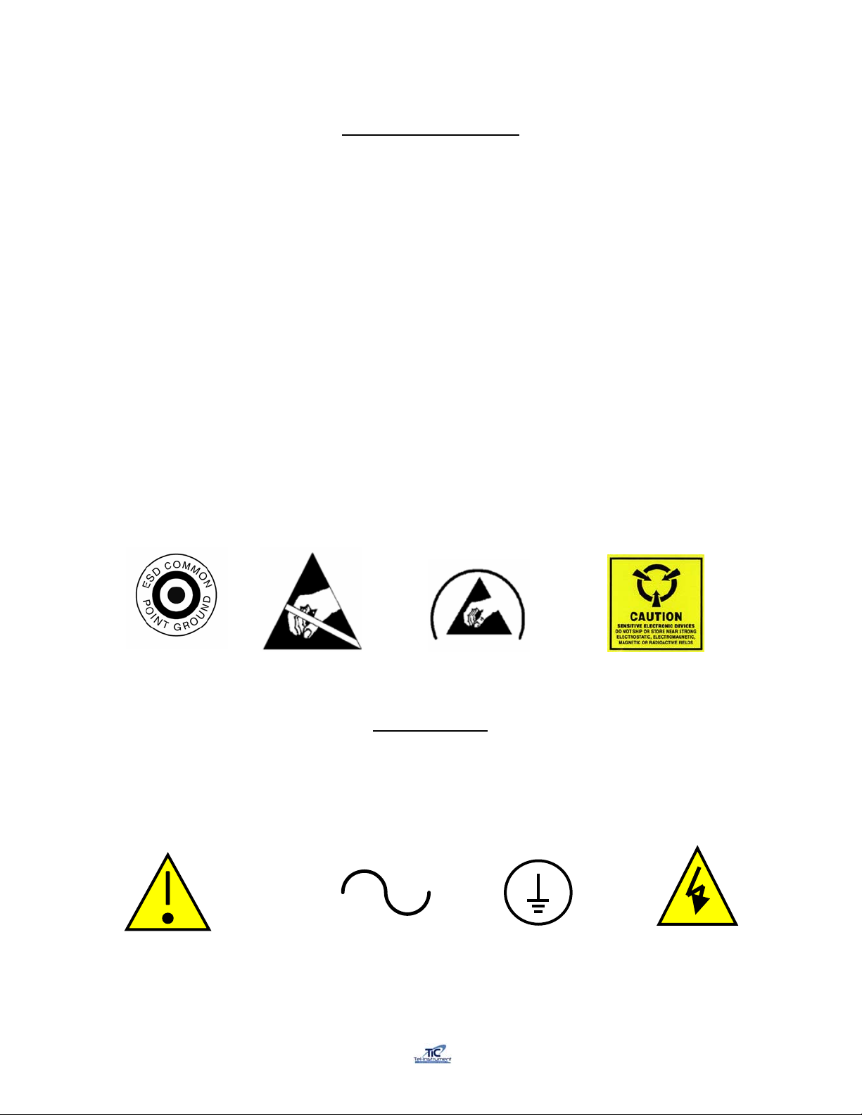
ESD Safety and Protection
Many parts contained in the Test Set are sensitive to ESD (Electro-Static Discharge) damage.
ESD can damage integrated circuits or semiconductors located within the Test Set. Only qualified
personnel should service the Test Set to prevent damage. The following are guidelines to avoid
ESD damage while still performing tests and or maintenance. These guidelines are meant only as
a reminder, consult local directives and follow standard operating procedures before servicing, or
repairing the Test Set.
•Wear a properly grounded wrist strap and remain in contact with an approved grounding
point.
•Do not touch the connector pins or backplanes of ESD Sensitive circuits or parts.
•Ensure soldering irons are grounded before use.
•Do not remove any components or disconnect any connectors located in the Test Set with
the power “ON”.
•Properly ground all test equipment being utilized. Refer to the test equipment operating
manual for information.
•Place all removed components or parts in or on an approved conductive package.
Most ESD devices or circuits and common points are readily identified utilizing several different
methods. Below are some examples.
CE (IEC) Marking
The Following Symbols may be utilized in different locations throughout the Manual and are also
located on and in the Test Set. Observe these warnings and markings and follow standard
electrical safety anytime you utilize live circuits.
Caution Alternating Current Caution,
risk of
electrical shock
Protective Conductor
Terminal

VOLUME 1
OPERATIONAL PROCEDURES

Rev E TR-220 90 008 088-1
i
TR-220 TABLE OFCHANGES1
Date REV ECO Page Description
Prelim. Initial Release
07 Sep 03 A Initial Release
15 July 04 B Updated procedure explanations
16 Mar 05 C 2-5 & 6, 13, 17,
22, 43-46 Provided Detailed EHS and ADS setup
and display info
01 Jul 05 D Chapter 3-6 Added CHAPTERS 3, 4, 5, &6
9 May 07 E Chapter 1 and 2 Add test capability for measuring reply
delay, jitter, MS P6 pulse amplitude
variation, and MS P5 pulse width
1Changes are also denoted with a solid bar in the Left margin of each affected page.

Rev E TR-220 90 008 088-1
ii
Table of Contents
Chapter Page
Table of Changes……………………………………………………………………. i
List of Illustrations…………………………………………………….……………… vii
List of Tables……………………………………………………….………………… viii
I INTRODUCTION
Section A- General Information
1.1 Scope of Manual…………………………………………………………… 1-1
1.2 Purpose and Function of Equipment…………………………………….. 1-1
1.3 Regulatory Responsibilities…………………………………………......... 1-2
1.4 Warranty…………………………………………………………………….. 1-3
1.4.1 Obtaining Warranty Service………………………………………… 1-3
1.4.1 Shipping and Packing the Test Set………………………………... 1-4
Section B- Equipment Description
1.5 Specifications………………………………………………………………… 1-5
1.6 Abbreviations, Acronyms, and Glossary of Terms…………………....... 1-7
II PREPARATION FOR USE AND OPERATION
Section A- General Information
2.1 General………………………………………………………………........... 2-1
2.2 Unpacking…………………………………………………………………… 2-1
2.3 Installation…………………………………………………………………… 2-1
2.4 Accessories…………………………………………………………………. 2-1

Rev E TR-220 90 008 088-1
iii
Table of Contents (continued)
Chapter Page
Section B- Operating Controls, Indicators, and Connectors
2.5 General………………………………………………………………........... 2-3
2.6 Controls, Indicators, and Connectors……………………………………. 2-3
Section C- Operating Instructions
2.7 General………………………………………………………………........... 2-5
2.8 Battery Operation…………………………………………………………… 2-5
2.8.1 Auto-Shutdown………………………………………………….. 2-6
2.9 TR-220 Supplied Antenna…………………………………………………. 2-6
2.9.1 Directional Antenna…………………………………………….. 2-6
2.9.2 Direct Connect………………………………………………….. 2-9
2.9.3 TAP-200 Antenna Coupler…………………………………….. 2-9
2.10 Initial Startup and Self-Test……………………………………………….. 2-12
2.11 Transponder Test Sequence……………………………………………… 2-13
2.12 Transponder Manual Sequence of Tests………………………………… 2-14
2.12.1 ATCRBS, Mode A/C Manual Testing………………………… 2-14
2.12.2 Mode S Manual Testing……………………………………….. 2-17
2.13 Transponder Automatic Sequence of Tests…………………………….. 2-24
2.13.1 ATCRBS, Mode A/C Automatic Testing……………………… 2-24
2.13.2 Mode S Automatic Testing…………………………………….. 2-26
2.14 Testing a Transponders “IDENT” Function……………………………… 2-28
2.15 TCAS Tests…………………………………………………………........... 2-29
2.15.1 Typical TCAS Concepts……………………………………….. 2-29
2.15.2 TCAS Scenario Selection and Setup …….………………….. 2-29
2.15.3 Erasing the TCAS Scenario Memory………………………… 2-35
2.15.4 Testing a TCAS Equipped Aircraft……………………………. 2-36
2.16 DME Tests………………….……………………………………………….. 2-41
2.16.1 DME Setup…….………………………………………………… 2-41
2.17 Mode S Enhanced Surveillance…………………………………………... 2-43

Rev E TR-220 90 008 088-1
iv
Table of Contents (continued)
Chapter Page
2.18 ADS-B and TIS Testing……………………………………………………. 2-47
2.18.1 ADS-B TX……………………………………………………….. 2-47
2.18.2 ADS-B RX………………………………………………………. 2-50
2.19 RS-232 Download Procedures…………………………………………… 2-52
2.19.1 Setting Up your Computer for RS-232 Download………….. 2-53
2.19.2 Downloading the Data…………………………………………. 2-54
2.19.3 Loading the Data to a Microsoft Excel File………………….. 2-55
List of Illustrations (Figures)
Figure Title Page
1-1 TR-220 Multifunction Test Set…………………………………………………. 1-1
2-1 TR-220 Accessories…………………………………………………………….. 2-2
2-2 Controls, Indicators, and Connector Locations………………………………. 2-3
2-3 Directional Antenna Gain……………………………………………………….. 2-7
2-4 Directional Antenna Setup……………………………………………………… 2-8
2-5 TAP-200………………………………………………………………………….. 2-10
2-6 TAP-200 Placement…………………………………………………………….. 2-11
2-7 TAP-200 Adjustment……………………………………………………………. 2-11
2-8 Sequence of Tests………………………………………………………………. 2-13
2-9 Caution, Warning, and Collision Areas……………………………………….. 2-29
2-10 Typical TCAS I Display…………………………………………………………. 2-30
List of Tables
Table Title Page
2-1 TR-220 Accessories……………………………………………………………. 2-2
2-2 Controls, Indicators, and Connectors………………………………………… 2-4
2-3 Preprogrammed TCAS Scenarios……………………………………………. 2-30
2-4 TCAS Intruder Parameters…………………………………………………….. 2-33
2-5 Additional TCAS Intruder Scenarios…….……………………………………. 2-34
2-6 TIS Intruders…………………………………………………………………….. 2-51

Rev E TR-220 90 008 088-1
1-1
CHAPTER I
INTRODUCTION
SECTION A
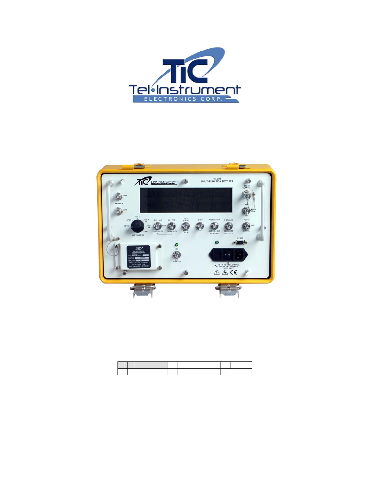
1.1 Scope of Manual
This manual is intended to familiarize the operator with the operating and maintenance
procedures necessary to utilize the TR-220 Multifunction Test Set. Here-in after known as the
T/S, Test Set, or TR-220.
Figure 1-1
TR-220 Multifunction Test Set
1.2 Purpose and Function of the Equipment
The TR-220 Test Set tests airborne ATCRBS, MODE A/C, and MODE S transponders, TCAS I/II
systems, DME equipment, and ADS-B and TIS Transponders. It is self-contained and battery
operated that requires no direct hardware connection to the Unit Under Test (UUT).
For transponder testing, the Test Set simulates secondary radar to receive and radiate signals to
the UUT from antennas supplied with the Test Set. For accurate power and frequency

Rev E TR-220 90 008 088-1
1-2
measurements, the Test Set can be directly connected to the UUT without the use of additional
hardware.
For TIS testing, the Test Set transmits simulated Intruder Flight Data, which is then shown on the
TIS display to verify results.
The Test Set will receive and Decode 1090 MHz ADS-B data including squitter type, airborne
position, surface position, aircraft IDENT category, Airborne velocity, Latitude/Longitude,
North/South velocity, and East/West Velocity. The ADS-B TX function allows the operator to
receive, decode, and display ADS-B squitters. The ADS-B RX function permits the operator to
simulate a 1090MHz squitter. The TR-220 can be configured to transmit an airborne or surface
position squitter containing position, altitude, velocity, heading, aircraft category, flight ID, and
Mode S address.
The simulation of an intruder aircraft converging on the Aircraft Under Test (AUT) accomplishes
TCAS testing. The simulated target will be displayed on the TCAS display so the operator can
ensure proper advisories.
DME tests simulate an aircraft at a simulated speed converging to or from a selected distance. By
comparing the Test Set displayed distance to the DME under test display, the operator can
confirm proper DME operation.
1.3 Regulatory Responsibilities
Effective April 6, 1987, The Federal Aviation Administration (FAA) has required certain tests be
performed on transponders, both conventional ATCRBS and MODE S. In preparation for the
installation of new air traffic control radar facilities, the FAA required new measurements to be
performed on existing transponders and instituted required tests for MODE S transponders. FAR
(Federal Aviation Regulation) Part 43, Maintenance, Preventive Maintenance, Rebuilding and
Alteration section has been modified to reflect current technologies and improvements. Tel-
Instruments has met all FAA requirements and recommends that the user of this type of
equipment review the appropriate FAR or contact the manufacturer of their particular model of
transponder to ensure that the current procedures and limitations are being correctly adhered to.
Eurocontrol has also incorporated new regulations for Mode S Elementary and Enhanced
Surveillance. These requirements include Selective Identifiers for high-density traffic areas and
will become mandatory beginning in May of 2003 for Elementary Surveillance and March 2005 for
Enhanced Surveillance. The TR-220 Test Set has the capability to thoroughly test these new
functions to comply with upcoming requirements. If you would like further information regarding
these requirements, visit www.eurocontrol.int/.

Rev E TR-220 90 008 088-1
1-3
1.4 Warranty
The Tel-Instrument Electronics Corporation warrants that each product it manufactures is free
from defective material and workmanship for a period of two (2) years subject to the following
terms and conditions. Tel-Instrument Electronics Corp. will remedy any such warranted defect
subject to the following:
This warranty requires the unit to be delivered by the owner to Tel-Instrument intact for
examination, with all transportation charges prepaid to the factory, within two (2) years from the
date of sale to original purchaser. Tel-Instrument will solely determine when such defect exists.
This warranty does not extend to any of Tel products which have been subject to misuse, neglect,
accident, improper installation, or used in violation of operating instructions. This warranty does
not extend to units which have been repaired, calibrated, or altered in any way by a facility that is
not approved, in writing, by Tel-Instrument Electronics Corp. to perform such work. This warranty
does not apply to any product where the seals or serial number thereof has been removed,
defaced or changed, nor to accessories not of our own manufacture.
Repair parts will be made available for a minimum period of five (5) years after the manufacture
of this equipment has been discontinued.
This warranty is in lieu of all other warranties expressed or implied and all such other warranties
are hereby expressly excluded. No representative or person is authorized to assume for us any
other liability or warranty in connection with the sale of Tel’s products.
This warranty does not cover or include batteries (batteries have a separate 90 day warranty).
Additional information with regard to the applications and maintenance of this equipment will be
available from time to time.
1.4.1 Obtaining Warranty Service
In the event the Test Set may require service or repair that is included under the
warranty provided with the Test Set; the following is necessary to ensure proper
handling:
1. Contact Tel-Instrument Customer Support before shipping any Test Set
back under a warranty condition.
Tel-Instrument Electronics Corp. Customer Support can be reached by
calling:
¾(201) 933-1600 (telephone)
¾(201) 933-7340 (fax)
2. The Customer Support Department will discuss the matter and if validated,
issue an RMA (Return Material Authorization) number and form. Do not
return any product without first receiving this authorization.
3. The Test Set must be returned with the completed RMA form. This will
ensure prompt handling and expedited service.
4. Products must be returned in the Original Shipping Container (see
Paragraph 1.4.1). If the original container is no longer available, please
contact Tel-Instrument for guidance. Include in or on the shipping container
the following information:

Rev E TR-220 90 008 088-1
1-4
•RMA Form on top of the product
•The assigned RMA number written in bold letters on the
outside of the shipping container
•Model, Serial Number, and specific details regarding the
problem
•POC name, return address, telephone number, and
email address
5. Freight Charges to the factory are the responsibility of the owner/operator.
Tel-Instrument will provide return shipping if the problem is determined to be
warranty covered.
1.4.2 Shipping and Packing the Test Set
1. Repackage the Test Set in the Original container utilizing the provided
packing material. Do Not Ship the Test Set with out using a shipping
container, this will prevent damage to the case and or finish during transit.
2. Wrap the Test set within plastic sheeting and firmly seat the Test Set in
the original corner molds. Place all necessary documentation (RMA Form,
POC, etc…), on top of the Test Set.
3. Utilize Package Tape and seal all seams. If the use of an industrial box
stapler is used, be sure that they do not protrude through the box to
prevent injury to personnel handling the package.
4. Firmly affix a shipping label and mail the Test Set to the following:
Tel-Instrument Electronics Corp.
728 Garden Street
Carlstadt, NJ 07072
Attn: Repair Department

Rev E TR-220 90 008 088-1
1-5
SECTION B
EQUIPMENT DESCRIPTION
1.5 Specifications
Transponder Transmitter
Frequency 1030 MHz ± 10 kHz
Output Power > 4dBm
Modes A, C, S, ADS B TX/RX,
and TIS
Transponder Receiver
Frequency Frequency 1086.5 to 1093.5 MHz
Accuracy ± 200 kHz
Power Range 47 to 64 dBm
Accuracy ± 2 dB (direct connect)
± 3 dB (radiated)
Sensitivity Range. -50 to -87 dBm
Accuracy ± 2 dB (direct connect)
± 3 dB (radiated)
Reply Percent Range 0 to 100%
Accuracy ± 1%
DME
DME Receiver
Frequency Frequency Channel Freq +3.5 MHz
Accuracy ± 200 kHz
Sensitivity Range < -35 dB
DME Transmitter
Frequency Frequency 962 to 1213 MHz
Accuracy ± 100 kHz
Power ≥4 dB
TCAS
TCAS Transmitter
Frequency 1090 MHz ± 10 kHz
Output Power > 4dB
Modes C & S
Antenna Beamwidth…. 15° Sum & Diff Ports
30°Sumonly

Rev E TR-220 90 008 088-1
1-6
TCAS Receiver
Frequency 1026.5 to 1033.5 MHz
Power 47 to 64 dBm
Physical Characteristics
Packaging MIL-PRF-28800 Style C
Size 14.5 x 9.4 x 6.5 inches
Weight. 20 pounds
Operating Temperature -28° to +55° C
Battery Operation. 8 hours at a 20%
DutyCycle
AC Operation/Charging 100 – 240 VAC
47 – 440 Hz

Rev E TR-220 90 008 088-1
1-7
1.6 Abbreviations, Acronyms and Glossary of Term1
A/A Air to Air
A/A B Air to Air Beacon
ac or AC Alternating Current
A/D Analog to Digital
ADS-B Automatic Dependent Surveillance - Broadcast
Address The unique code to which a MODE S transponder replies. This is not to
be confused with the 4096 code used for identifying ATCRBS
transponders. The address of a MODE S transponder is not alterable by
the pilot or crew.
Altitude The pressure altitude of the aircraft as transmitted by an ATCRBS or
MODE S transponder. This information is obtained from an external
sensor and transmitted to the transponder.
AM Amplitude Modulation
ATCRBS Air Traffic Control Radar Beacon System
ATCRBS/MODE S All Call Interrogation that causes all ATCRBS/MODE S transponders to reply.
ATC Air Traffic Control
AUT Aircraft Under Test
BIT Built in Test
Comm Refers to the communications and data-link capability of a MODE S
transponder. There are four (4) capabilities: No Comm, Comm A/B,
Comm A/B/C and Comm A/B/C/D. The Comm. capability is displayed
when the transponder is determined to be a MODE S.
CW Continuous Wave
D/A Digital to Analog
DAP Downlinked Aircraft Parameter
dB Decibel
dBm Decibels above 1 milliwatt
dc or DC Direct Current
DME Distance Measuring Equipment
DPSK Differential Phase Shift Keying. The method of modulation used for the
selective MODE S uplink interrogations.
DF Downlink Format. The format included in a MODE S transponder reply to
an interrogation or squitter message that indicates the type of message.
ELM Extended Length Messages
FAA Federal Aviation Administration
FAR Federal Aviation Regulation
FIFO First In First Out
FREQ Frequency
ft. Feet
G/A Ground to Air
Hz Hertz
IF Intermediate Frequency
IFF Identify Friend or Foe
KHz Kilohertz
kts. Knots
LCD Liquid Crystal Display
LED Light Emitting Diode
1Further definitions may be found in the following reference books and documents: Helfrick, A.D. Principles of Avionics.
Leesburg: Quality Books, 2000. RTCA/DO-181B. Minimum Operational Performance Standards for Air Traffic Control
RADAR Beacon System/Mode Select (ATCRBS/Mode S) Airborne Equipment. Washington D.C.: 1999. United States.
Federal Aviation Administration. Federal Register Fed 3, 1987 FAA rules Part 91.

Rev E TR-220 90 008 088-1
1-8
MODE S A secondary radar system where transponders can be individually
interrogated or selected (the “S” in MODE S) so that in a crowded air
traffic area, the amount of interference or garble can be reduced to a
minimum.
MHz Megahertz
nmi. Nautical mile
ns Nanosecond
PAM Pulse Amplitude Modulation
PDME Precision Distance Measuring Equipment
PMCS Preventative Maintenance Checks and Services
PPM Pulses per Minute
PRF Pulse Repetition Frequency
PW Pulse Width
PWR Power
RA Resolution Advisories
Receiver Efficiency The Test Set’s Measurement of valid replies received. Displayed as a
Percentage.
Reply Codes A transmitted response, from the airborne transponder, to an
interrogation. Commercial transponders responses are designated as
either ATCRBS/A where the reply includes the pilot selected 4096 ID
code, or ATCRBS/C, where the reply includes the aircraft pressure
altitude. These same responses for military transponders are designated
as MODE 3A and MODE 3C. See Mode S for further information.
RF Radio Frequency
RMS Root Mean Square
R/T Receiver Transmitter
SIF Selective Identification Feature
SLS Side Lobe Suppression. A pulse transmitted from an omni-directional
antenna used as a reference level to prevent replies to interrogations
received from the secondary radar antenna side lobes.
Squitter The self-generated transmissions made by a MODE S transponder, not in
reply to an interrogation, for the use of the collision avoidance system.
And ADS-B Receivers and Transmitters.
SSR Secondary Surveillance Radar
Surveillance Altitude An interrogation that causes only the addressed MODE S transponder to
reply.
Surveillance ID An interrogation that causes only the addressed MODE S transponder to
reply to its “4096” code.
TA Traffic Advisories
TACAN Tactical Air Navigation
TCAS Traffic Alert and Collision Avoidance System
TIS Traffic Information System
TX Transmitter
UF Uplink Format. The format in a MODE S interrogation that indicates the
type of reply expected.
VORTAC VOR and TACAN (co-located)
VOR VHF Omni-Directional Range
VSWR Voltage Standing Wave Ratio
WOW Weight On Wheels
UUT Unit Under Test
XPDR Transponder
XPDR UT Transponder Under Test
4096 Code This refers to the octal number dialed into either an ATCRBS MODE A or
MODE S transponder by the pilot. This is to be distinguished from the
address of the MODE S transponder, which cannot be changed.

Rev E TR-220 90 008 088-1
2-1
CHAPTER II
PREPARATION FOR USE AND OPERATION
SECTION A
GENERAL INFORMATION
2.1 General
This Chapter contains all necessary information on the initial unpacking, inspection, and set-up of
the TR-220 Multifunction Test Set (Hereinafter called the TR-220, Test Set, or T/S).
2.2 Unpacking
When receiving the TR-220 for the first time, ensure that there is no damage to the shipping
container. Carefully unpack the unit and save the shipping container in a safe location for
shipping or extended storage.
Examine the unit for obvious signs of damage. Check all displays, switches, and connectors
before utilizing the Test Set.
If any damage is found, DO NOT use the Test Set until a determination of the Test Sets functions
can be assessed. Contact Tel-Instrument as soon as possible for further instructions.
The TR-220 Test Set batteries were installed and fully charged when shipped from the factory.
2.3 Installation
The Test Set is fully functional and ready to use from the factory. There are no installation
procedures applicable.
2.4 Accessories
Once opening the Test Set Cover, ensure all the accessories that were purchased with the Test
Set are accounted for. The TR-220 comes standard with the following (See next page):

Rev E TR-220 90 008 088-1
2-2
# NOMENCLATURE P/N QTY
1 Test Set 90000088 1
2 Cable Assembly, AC Power Cord 75010025 1
3 Cable Assembly, Direct Connect 75010186 1
4 Extender Cable Assembly, Directional
Antenna 75010078 1
5 Directional Antenna Cable Assembly 75010208-02 1
6 Directional Antenna Assembly 89001158-07 1
7 Directional Antenna Handle Assembly 88001002 1
X TAP-200 Antenna Coupler Optional
XX TR-220 Manual (Not Shown) 90008088-1 1
TR-220 Accessories
Table 2-1
TR-220 Accessories
Figure 2-1
1
2
3
4
7
65

Rev E TR-220 90 008 088-1
2-3
SECTION B
OPERATING CONTROLS, INDICATORS, AND CONNECTORS
2.5 General
This section covers location and function of the operating controls, indicators, and connectors. All
controls, indicators, and connectors are located on the front panel of the Test Set.
2.6 Controls, Indicators, and Connectors
Figure 2-2 and Table 2-2 indicates the location and the function of each item on the front panel of
the Test Set.
Controls, Indicators, and Connectors
Figure 2-2
1 2 3 4 5 6 7 8 9 10 11 12
1314151618 17
Table of contents
Other TIC Test Equipment manuals


