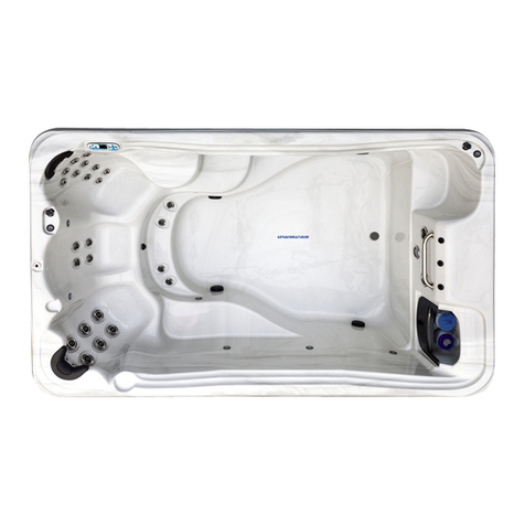
TidalFit Active EP-12 User manual

6
ELECTRICAL REQUIREMENTS AND
INSTALLATION
The following information is provided for hooking up electrical supply to
your new pool. A qualied, licensed, electrician must perform this work.
Failure to follow these instructions will terminate all warranty coverage
and can cause serious injury or death.
Your 60 Hz pool is preset at the factory to run on 240 V with a 48Ainput.
This feature gives you the most performance out of your pool. This will
require a 240 V, 60-amp GFCI
Your export 50 Hz pool is preset out of factory to run 230 V-240 V 3
wires 30 A max input. This product must always be connected to resid-
ual current device (RCD) having a trip current of not more than 30 mA.
ELECTRICAL WIRING
WARNING: Your pool must be wired by a certied electrician and
according to these instructions. Failure to do so will terminate all
warranties and all listings from the independent listing facility.
1) The TidalFit requires a 240 VAC dedicated system. The pool must be
hard wired to the power supply, with no plug-in connections, extension
cords, or sharing of service.
2) The pool requires that you run 6 (10 mm²) or 8 (8.4 mm²) AWG cop-
per wire, depending on the GFCI size. Do Not Use Aluminum Wire.
3) The power supply must have a suitable Ground Fault Circuit Inter-
rupter (GFCI), according to Section 422-20 of the National Electrical
Code, ANSI/NFPA 70-7987 or other national installation requirement
with a residual current device (RCD) having a trip current of not more
than 30 mA. This could be used as the shut-off switch, which must be
installed in plain view of the pool. This electrical service must be readily
accessible to the pool occupants, but must not be within 5 feet of the
pool.
4) Use only non-metallic conduit and ttings when installing power to
the spa.
5)After your pool has been positioned, route lines through the knockout
on the left or right front corner of the pool.
6) Connect the power to the pool.

GFCI PROTECTION
NOTE: The GFCI section does not apply on EL systems used
outside the United States. This GFCI section does not apply to GL
Systems.
Your pool may be equipped with a GFCI Protection feature. If your pool
does not have this feature enabled, the GFCI Trip Test must occur to al-
low proper pool function.
Within 1 to 7 days after startup, the pool will trip the GFCI to test it. (The
number of days is factory programmed.) The GFCI must be reset once
it has been tripped. After passing the GFCI Trip Test, subsequent GFCI
trips will indicate a ground default or other unsafe condition requiring the
power to the pool to be shut off.
Warning: The owner should test and reset the GFCI on a regular basis
to verify it’s function
Once the GFCI is tripped by the test, reset the GFCI and the pool will
operate normally from that point. You can verify a successful test by
navigating to the “9FC” item as described above, pressing
“Jets 1” and then pressing the “Warm” button until you
see “9SP”. The code signies GFCI Status - Passed.
The system will exit this menu in 30 seconds if no buttons are pressed.
GFCI TRIP TEST PROCEDURE
The installer can cause the GFCI Trip Test to occur sooner by initiating
it with the following button sequence.
Press “Warm”, then “Jets 1”, then “Light.”
(Each press must be within 3 seconds of the previous press.) Press
the “Warm” button repeatedly until “9FC” is displayed.
Press “Jets 1” to select it. Press the “Warm” button until
“9t.n” is displayed.
Press “Jets 1” to initiate the GFCI Trip Test.
The GFCI should trip within several seconds and the pool should shut
down. If it does not, shut down the power and manually verify that a
GFCI breaker is installed and that the circuit and pool are wired cor-
rectly. Verify the function of the GFCI with it’s own test button. Restore
power to the pool and repeat the GFCI Trip Test.
ELECTRICAL REQUIREMENTS AND
INSTALLATION
7

8
60 Hz GFCI WIRING SCHEMATIC (EP-16)
240 Volt Residential Wiring Schematic with G.F.C.I.
House Breaker Box G.F.C.I. Breaker Box
120 VAC 120 VAC
Neutral
Green
Red
Black
Green
Black
White
White
Red
VFD
Red
Black
Green
Outside Ground
Rod
Green White
Black
Red
Red
To VFD
Motor
Red
Black
Red
Black
Red
Black Black
Red
Black
NOTE: THE POWER IN TO THIS CONTROL DOES NOT HAVE A COMMON LINE IN,
ONLY A GROUND. DO NOT HOOK A COMMON TO A POWER IN TERMINAL! THIS
WILL DAMAGE THE UNIT
IMPORTANT: REQUIRED SIEMENS 60A GFCI CIRCUIT BREAKER TO OPERATE
THE TIDALFIT EP-16
VFD Control Box
Spa System Box
Grounding Bar
Green
White
Green
Green

60 Hz GFCI WIRING SCHEMATIC (EP-12/14/15)
50 Hz RESIDENTIAL WIRING SCHEMATIC
230 Volt/50 Hz Residential Wiring Schematic with 2 Pole RCD Breaker Box
230 VAC House Breaker Box RCD Breaker Box Spa System Box
Outside
Ground
Rod
Blue (Nuetral)
Brown (Hot)
Test for Voltages by placing probes on these locations
230 VAC
“Live Wire”
Neutral
+
Ground
Green
Yellow
(Ground)
Green
Yellow
(Ground)
Brown
(Hot)
Blue
(Neutral)
Blue (Neutral)
Blue
(Neutral)
Green
Brown (Hot)
1
3
2
4
5
6
7
8
9
10
11
12
240 Volt Residential Wiring Schematic with G.F.C.I.
House Breaker Box G.F.C.I. Breaker Box Spa System Box
Test for Voltages by placing probes on locations
Red
When Probes Are Placed
5
6
8
9
12
Black
White
10
11
7
13
14
15
3
2
1
4
6
7
Outside
Ground
Rod
Red
Hot
White
Green
Red (Hot)
Black Hot
Red Hot
White
White
Green
Red
Hot
Black
120 VAC
neutral
120 VAC
Green Ground Wire
to Ground Bar
Red
Hot
Green
White
Bottom View
of G.F.C.I.
Black
White
Red
Hot
Black
Correct
Voltage
0 V
108 V-132 V
216 V-264 V
[3-4] [5-8] [5-9] [12-13]
[1-3] [5-6] [5-10] [12-14] [13-14]
[2-3] [5-7] [5-11] [12-15] [13-15]
[1-2] [6-7] [10-11] [14-15]
Green
9

FREQUENCY DRIVE WIRING DIAGRAM (EP-16)
FREQUENCY DRIVE WIRING DIAGRAM
GFCI
BREAKER
GROUNDING
BAR
GREEN GROUND) CONNECT TO
GROUNDING BAR WHITE (NUETRAL)
RED BLACK
GROUND
POWER IN
220
LINE 1
POWER IN
220
LINE 2
POWER IN
BALBOA
CONTROL
GROUND
NOTE: THE POWER IN TO THIS CONTROL DOES NOT HAVE A COMMON LINE IN,
ONLY A GROUND. DO NOT HOOK A COMMON TO A POWER IN TERMINAL! THIS
WILL DAMAGE THE UNIT
TOUCHPAD
CONTROL
IMPORTANT: REQUIRED SIEMENS 60A GFCI CIRCUIT BREAKER TO OPERATE
THE TIDALFIT EP-16
10
Other manuals for Active EP-12
1
This manual suits for next models
3
Table of contents
Other TidalFit Swimming Pool manuals
Popular Swimming Pool manuals by other brands

BSVILLAGE
BSVILLAGE NaturalWood 560 Assembly manual
Outside Living Industries
Outside Living Industries ubbink UrbanPool Note of assembly
Oval
Oval SP493613B instruction manual

Bestway
Bestway Power Steel Series owner's manual
Everbilt
Everbilt THD1085 Use and care guide
Bestway
Bestway FLOWCLEAR 5615G owner's manual
