Tides Marine SmartSeal User manual

Installation Manual
Temperature Sensor System
®
SmartSeal
Main Control Unit
12V Battery
NMEA 2000
Terminator
Male
NMEA 2000
Terminator
Female
NMEA
2000
Tee
Connector
NMEA
2000
Power
Tee
Sensor
Cable
To Water
Pick-Up
NMEA 2000
Drop Cable +-
Fuse
Ignition
or Inline
Switch
To Neutral
Safety Switch
Siren

Table Of Contents
Smart Seal System Introduction
System Overview .........................................................................
Functional Overview .....................................................................
Installation Overview ....................................................................
System Components
Main Control Unit ..........................................................................
External Siren ...............................................................................
Remote Monitoring Unit ................................................................
Sensor / Cabling ...........................................................................
Network Hardware ........................................................................
Installation
Step One: Main Control Unit..........................................................
Step Two: SmartSeal Harness-Connecting...................................
Temperature Sensor
Step Three: Connecting the Neutral Safety Switch........................
(non-NMEA Vessels)
Step Four: Installing External Siren...............................................
Step Five: Remote Monitoring Units..............................................
Step Six: Connecting To Power......................................................
Reference
Installation Templates.....................................................................
NMEA 2000 Connector Pin-Outs....................................................
NMEA 2000 Network Fundamentals..............................................
System System Diagrams:
1- Single Engine- No Remote....................................................
2- Twin Engines- No Remotes...................................................
3- Single Engine With Remote...................................................
4- Twin Engines With 2 Remotes..............................................
5- Single Engine With Remotes - NMEA 2000 Equipped..........
6- Twin Engines With Remotes - NMEA 2000 Equipped..........
Specifications.................................................................................
Certifications..................................................................................
Warranty.........................................................................................
2
2
2
3
3
4
4
5
6
7
7
8
9
11
12
13
13
15
16
17
18
19
20
21
22
22

Introduction
This manual will describe how the SmartSeal system works, what
the various system components are and how to install them.
System Overview
The SmartSeal Temperature Sensor System is designed to
compliment Tides Marine’s SureSeal Shaft Seal Systems on
vessels with single or twin engines. Its purpose is to detect and
warn of various vessel conditions which could potentially lead to
shaft seal damage or failure. It is compatible with vessels which
utilize the NMEA 2000 communication protocol for connecting
marine electronics, sensors and display units to a backbone
network for centralized monitoring of various types of vessel
information. It is also designed to operate on non-NMEA 2000
equipped vessels as well on vessels with certain other networks
via a converter (e.g. NMEA 01830).
Functional Overview
The SmartSeal System is comprised of a number of components
designed to work with a wide range of vessel types and
installation needs. At the heart of the system is a Main Control
Unit which is located in the engine compartment. Connected to
this unit are temperature sensors for each shaft seal in use.
Remote Monitoring Units can be connected and placed in other
areas of the vessel as can a remote external siren. In operation,
temperature status data is displayed on both the Main and
Remote unit’s control panels. When connected to a vessel’s
NMEA 2000 onboard network, temperature data is also sent to the
main or auxiliary computer display. In the event that the
temperature of the shaft seal(s) or the engine compartment
exceeds the normal operating range limit, visible and audible
alerts are initiated so that corrective action can be taken.
Installation Overview
This manual describes the installation procedures for the various
Smart Seal system components. There are many different types of
installations possible. Six system configurations are illustrated and
should be reviewed prior to beginning.
2

System Components / Features:
Siren
P/N SP-SS-SIREN
Main Control Unit,
Bulkhead Mount
Single Engine
P/N TPS-BH-SE
Main Control Unit,
Bulkhead Mount
Twin Engine
P/N TPS-BH-TE
Main Control Unit
External Siren
PORT Side
Harness
Connector
STBD. Side
Harness
Connector
Ambient Temp.
Sensor
Temp. Status
Indicators
Alarm/Siren
Control
Onboard Alarm
Speakerl
Remote Unit
/ NMEA 2000
Connector
3

Remote Monitoring Unit,
Bulkhead Mount
Single Engine
P/N TPS-RSBH
Sensor Cable
Extension,
Length 10M
P/N TPS-SCE
Harness- (Sensor,
Siren, NSS)
Length 10M
P/N TPS-SC
Remote Unit Monitoring,
Panel Mount
Single Engine
P/N TPS-RSPN
Remote Monitoring Unit
SmartSeal Cabling
Remote Monitoring Unit,
Panel Mount
Twin Engine
P/N TPS-RDPN
Temp. Status
Indicators
Onboard Alarm
Speaker
Remote Unit,
Bulkhead Mount
Twin Engine
P/N TPS-RDBH
Main Control Unit
/ NMEA 2000
Connector
4

Network Hardware
System Components:
N2K Drop Cable,
Length 1M
P/N TPS-DC-1M
N2K Drop Cable,
Length 10M
P/N TPS-DC-10M
N2K Tee Connector
P/N TPS-T-CONN
N2K Power Tee
P/N TPS-PC
N2K Terminator, Male
P/N TPS-TERM-MALE
N2K Terminator, Female
P/N TPS-TERM-FEMALE
5

Installation
The following outlines the recommended installation procedure for
the SmartSeal system.
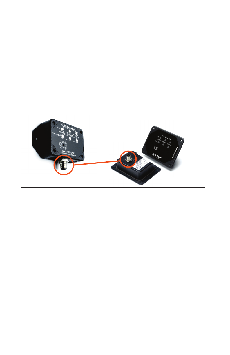
Step One: Installing the Main Control Unit
The Main Control Unit (MCU) is to be located in the engine
compartment mounted on a bulkhead / vertical surface where the
front panel is both visually and physically accessible.
Placement should also allow for the most direct routing of
wires/cables.
The unit has two types of connectors on the bottom of its
enclosure. The first is used to connect the SmartSeal wiring
harness for connecting the shaft seal sensor(s), neutral safety
switch (non NMEA vessels) and optional remote siren. The second
is used for connecting the Remote Monitoring Unit (RMU) and
12VDC power source or to connect to an existing NMEA 2000
network.
Using the mounting flanges on the enclosure, the unit should be
leveled and affixed with SS pan head screws. A full size template is
included for hole placement.
Mounted MCU
Cable / Harness Connectors
6

Step Two: Smart Seal Harness- Connecting the
Temperature Sensor(s)
The shaft seal temperature sensor is pre-attached to the black
SmartSeal harness cable. It needs to be connected to the water injection
fitting on the SureSeal being used. Connect the harness connector to the
MCU then route the sensor cable to the shaft seal. Twin engine systems
have two harnesses included, one for each SureSeal.
To connect the sensor to the injection fitting, remove one of the clamp
screws (philips head screw driver and 5/16 wrench required) and open
the clamp. Reassemble the sensor clamp around the shoulder of the
fitting just below the water pick-up hose attached to the fitting. Tighten
fully and check that the sensor is secure. Dress the cable(s) back to the
MCU to avoid snagging/accidental damage. Screw-mount zip ties are
recommended for wire management. If additional wire is needed, a 10M
extension cable is available. Excess wire should be bundled and
secured. Sensor cables CANNOT BE SHORTENED.
Step Three: Connecting The Neutral Safety Switch
(For Non- NMEA 2000 Vessels)
An In-Gear connection is required on vessels not equipped with a NMEA
2000 network. For a twin engine vessel, both in-gear connections must
be made, one for each transmission. Typically, the connection is made
using the Neutral Safety Switch (NSS) installed in the transmission but, if
necessary, the connection can also be made at the helm shifter control.
See following diagrams for both types of connections.
The grey harness cable is used for the NSS. Connect the white wire to
the NSS switch + and the brown wire to the NSS - terminal. Route and
dress the NSS cable to the MCU. NSS cables can be shortened as
necessary. Unused NSS cables (NMEA 2000 applications) can be cut but
should be properly capped and not left exposed.
Temperature Sensor Attaching Sensor to fitting
(water hose removed for photo)
Finished connection
7

Step Four: Connecting The External Siren
(Optional)
The Siren is a recommended accessory due to typically noisy
engine rooms. Several different types of sounds can be selected
depending on how the unit is wired. The brown harness cable is
for the external siren. Connect the white (+) wire to the siren
terminal marked 12V and the brown (-) wire to the sound terminal
of your choice. Mount the siren to a surface where it will not be
exposed to moisture as they are not waterproof. Route and dress
the siren cable to the MCU. Siren cables can be shortened as
necessary. Unused siren cables (twin engine installations use
only one siren) can be cut but should be properly capped and not
left exposed.
Transmission NSS Connection Helm Shifter NSS Connection
Battery
+
+12VDC /
24VDC
-
--
-
--
-
--
-
--
Ignition
Switch
In-Gear
Indicator
(possible)
Gear+
(To MCU)
Gear+
(To MCU)
Gear+
(To MCU)
Gear+
(To MCU)
Starter
Solenoid
Vessel Ground Vessel Ground
Neutral
Safety
Switch
(Closed = Neutral)
Neutral
Safety
Switch
(Closed = Neutral)
8
Step Five: Connecting Remote Monitoring Unit(s)
The Remote Monitoring Units (RMU) are display extensions of the Main
Control Unit. On larger vessels, one or more RMUs are typically installed
in locations where they can be easily monitored.
Two mounting configurations are offered: Surface / Bulkhead mount
(identical to the Main Control Unit), and a panel mount design for
installing into Consoles or Helm Stations. A full size template is included
for panel mounting. Panel mount units have an integral gasket on the
underside of the flange to seal against moisture ingress in wet locations.
Both configurations are IP 66 Rated.
Surface mount remote units have their connector on the bottom like the
MCU and Panel mount versions have their connector on the back.
NOTE*
This part of the installation involves connecting to an existing NMEA
2000 network or (in the absence of a NMEA 2000 network), creating a
private SmartSeal system network. If not familiar with these types of
networks please read the Fundamental Network Tips pp.xx before
beginning.
For NMEA 2000 Installations:
Locate the point of the NMEA 2000 network where tie in will be easiest.
Ideally this will be centrally located and relatively close to the 12V power
source connection. If there are unused/ terminated tee connectors
available, run drop cables from them to the MCU and RMU units. If there
are no unused connections available, you must add them by inserting
tees to the existing network as follows:
Connect two N2K tee connectors together using the mating side legs.
Insert this tee assembly into the backbone run such that both remaining
side connectors are connected to their mating counterparts of the
existing network. Use the two new tee connections to connect the MCU
and RMU(s).
9

NMEA 2000
Terminator
Male
NMEA
2000
Tee
Connector
NMEA
2000
Tee
Connector
NMEA
2000
Power
Tee
Drop Cable
To RMU
Drop Cable
To MCU To 12V
Battery
NMEA 2000
Terminator
Female
Existing
NMEA 2000
Network
Additional SmartSeal
NMEA 2000
Network Components
12V Battery
+-
NMEA 2000
Terminator
NMEA 2000
Tee
Connector
NMEA 2000
Drop Cable
To RMU
NMEA 2000
Drop Cable
To MCU
Drop Cables
To Electronics
NMEA 2000
Tee
Connector
For Non-NMEA Installations:
Plan the mounting location for the RMU so that it can be connected
to the MCU directly using network drop cable(s). Tides offers several
cable length options. (10M, 4M, 2M, 1M plus bulk wire)
Connect a N2K tee connector to each side of a Power Tee. Add both
Male and Female terminators to the remaining two side legs.
Connect the drop cable from the RMU to one of the N2K connectors.
Connect the Drop Cable from the MCU to the other N2K connector.
The Power Tee cable is used to connect to the 12VDC power supply.
10
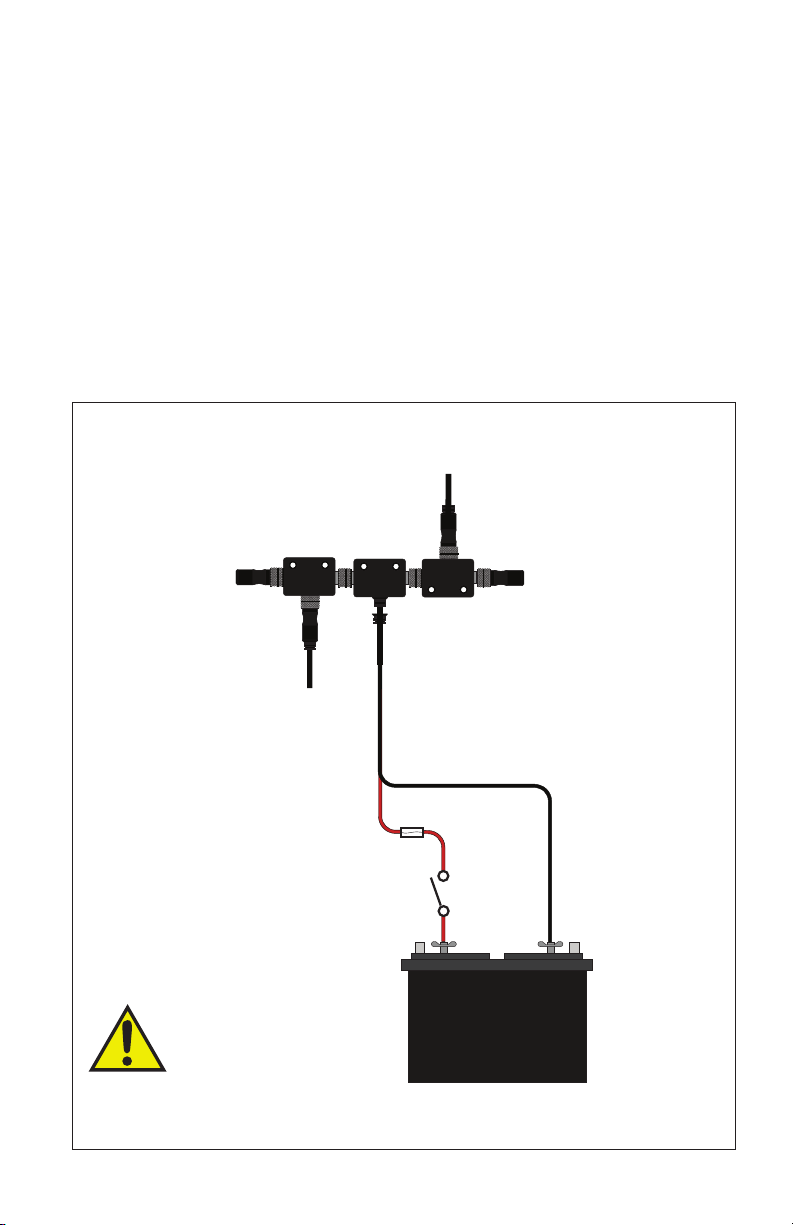
Step Six: Connecting To Power
(For Non-NMEA 2000 Vessels)
SmartSeal Systems which are connected to NMEA 2000 networks,
do not need to be separately connected to the power source as
the network is already connected and provides the necessary
operating power
Connect the Power Tee cable to a 12VDC Battery as shown below.
Make sure the + wire is fused.
DO NOT USE A VOLTAGE SOURCE
THAT IS NOT 12VDC +/- 3VDC AS IT
WILL DAMAGE THE SMARTSEAL SYSTEM
12V Battery
+-
Fuse
Ignition
or Inline
Switch
NMEA 2000
Terminator
Male
NMEA
2000
Tee
Connector
NMEA
2000
Tee
Connector
NMEA
2000
Power
Tee
Drop Cable
To RMU
Drop Cable
To MCU
NMEA 2000
Terminator
Female
11
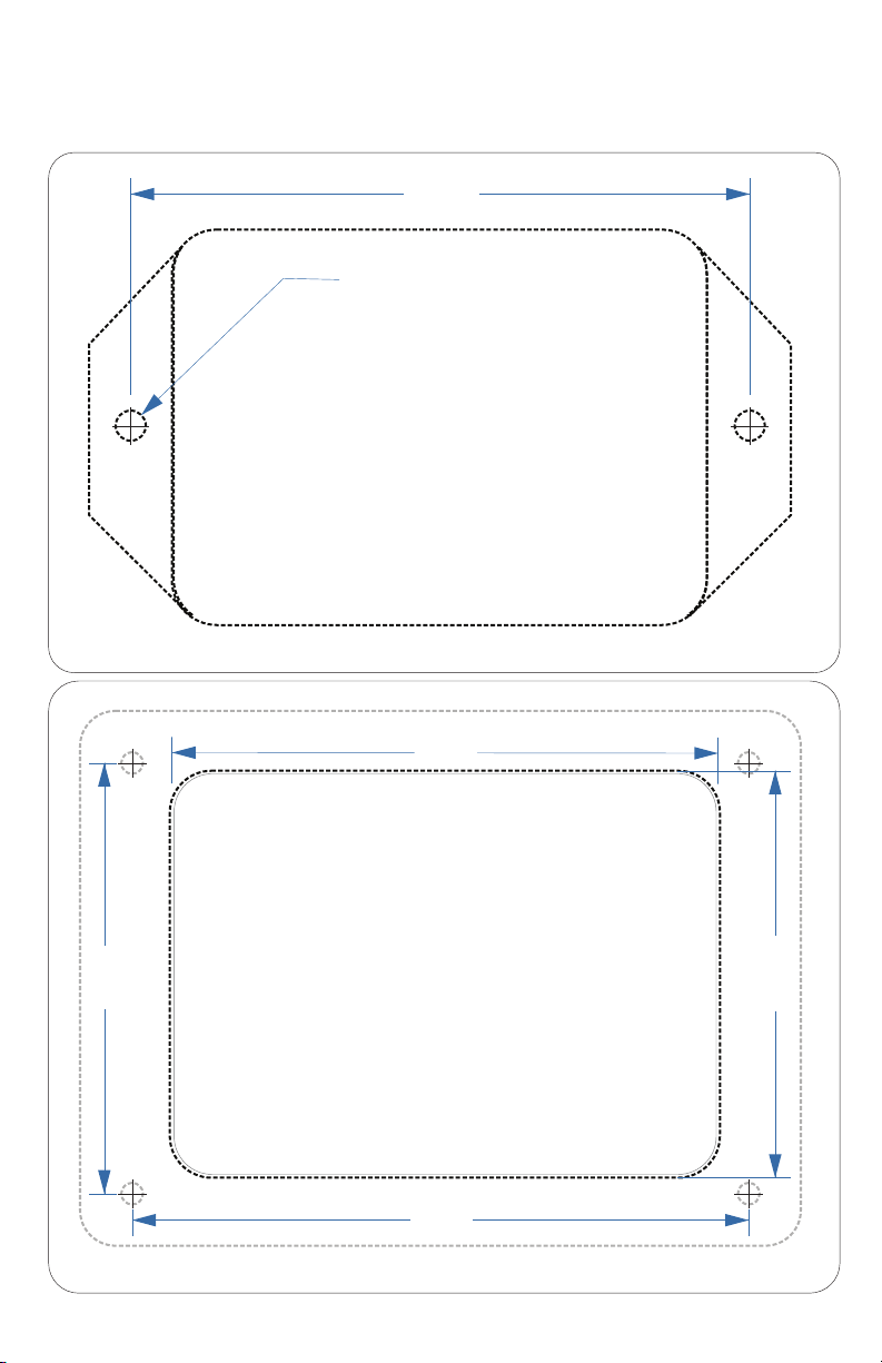
MCU / RMU Surface Mount Template
Panel Mount- RMU Template
Cut On Dotted Line
Cut On Dotted Line
Cut On Dotted Line
Cut On Dotted Line
3.87"
.188 DIA. TYP. 2 PL
FOR #8 SCREW
Mounting / Cutout Templates
3.41"
2.54"
3.85"
2.69"
12

NMEA Network Fundamentals / Tips
NMEA 2000
11
55 22
33
44
MaleFemale
Pin 1: Shield
Pin 2: NET-S. (Power Supply +)
Pin 3: NET-C. (Power Supply -)
Pin 4: NET-H. (CAN-H)
Pin 5: NET-L. (CAN-L)
Connector Pin-Outs
NMEA 2000 plug-and-play components make it easier than ever to
integrate marine electronics, allowing you to view, control and share
functions and information across a network of displays. Yet there are
some do’s and don’ts that ensure that your NMEA 2000 cable and
connections function properly. Here are six Network Fundamentals tips:
(courtesy of Garmin)
13
1 Power Up the Network
Remember that an NMEA 2000 network requires 12-volt DC power.
Special connectors with positive and ground wires (with inline fuses for
the positive wire) let you supply onboard power to the so-called
backbone – the main communication channel for the system. These
power cables should be connected near the center of the backbone in
order for the system to function properly.
2 Use 12 Volts DC Only
Make sure any power source you choose is 12 volts DC; do not
connect your NMEA 2000 network to any other power source such as
24 volts DC.

3 Avoid Long Strings of T-Connectors
As you add NMEA 2000-compatible electronics and sensors to the
backbone, there’s a tendency to string a number of T-connectors while
tying into the system. This is a mistake, as a long series of T-
connectors is prone to damage and broken connections. Replace these
long strings with T-junctions – two to four unified T-connectors. These
are more robust and compact; a four-way T-junction is 25 percent
shorter than a string of four connectors.
4 Keep Drop Cables Short
Avoid using long drop cables (the cables that connect your electronics
to the backbone). NMEA 2000 signals can be hampered by resistance,
which causes a reduction in voltage. The maximum length for a single
drop cable is 20 feet. If you require a longer cable run to connect an
item such as a transducer or sea-surface temperature sensor, use a T-
junction to either at the end or the middle of the run to tie in 12-volt
power. Augmenting the power in this manner helps prevent an
excessive drop in voltage.
5 Use the Sides of T-Connectors to Build a Backbone
By using only the sides of the T-connectors to assemble an NMEA
2000 backbone, you create a linear format. Also, use only the top of the
T-connector to attach devices and sensors.
6 Don’t Forget the Terminators
An NMEA 2000 backbone requires terminators at each end. You need
to use one female terminator and one male terminator at opposite ends
of your NMEA 2000 linear backbone.
14

Main Control Unit
12V Battery
NMEA 2000
Terminator
Male
NMEA 2000
Terminator
Female
NMEA
2000
Tee
Connector
NMEA
2000
Power
Tee
Sensor
Cable
To Water
Pick-Up
NMEA 2000
Drop Cable +-
Fuse
Ignition
or Inline
Switch
NOTE*
Tee connectors may be
connected directly to each
other or with Drop Cables
depending on installation.
To Neutral
Safety Switch
Siren
Single Engine Vessel, Without Remote
Normal Critical
Warning
Temperature Sensor
®
SmartSeal
TIDESMARINE
Schematic System Diagram 1
15

Main Control Unit
12V Battery
NMEA 2000
Terminator
Male NMEA 2000
Terminator
Female
NMEA 2000
Tee Connector
NMEA 2000
Power Tee
NMEA 2000
Drop Cable
Port
Sensor
Cable
Stbd.
Sensor
Cable
To Port
Neutral Safety Switch
To Stbd.
Neutral Safety Switch
To Water
Pick-Up
Port Engine
To Water
Pick-Up
Port Engine
Crossover Water Line Between Seals
NMEA 2000
Drop Cable
+-
Fuse
Ignition
or Inline
Switch
NOTE*
Tee connectors may be
connected directly to each
other or with Drop Cables
depending on installation.
Twin Engine Vessel, Without Remote
Siren
Normal Critical
Warning
Temperature Sensor
®
SmartSeal
TIDESMARINE
Port
Starboard
Schematic System Diagram 2
16

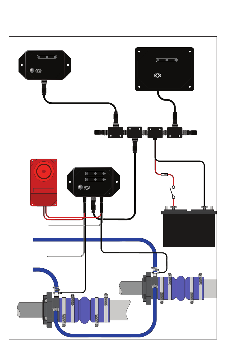
Main Control Unit
Sensor
Cable
To Water
Pick-Up
NMEA 2000
Drop Cable
To Neutral
Safety Switch
Siren
Normal Critical
Warning
Temperature Sensor
®
SmartSeal
TIDESMARINE
Remote Monitor Unit
(panel mount shown)
NMEA 2000
Terminator
Male
NMEA
2000
Tee
Connector
NMEA
2000
Tee
Connector
NMEA
2000
Power
Tee
NMEA 2000
Drop Cable
NOTE*
Additional
Remote Units
may be added to
the system
through the use
of additional Tees
12V Battery
NMEA 2000
Terminator
Female
+-
Fuse
Ignition
or Inline
Switch
Normal Critical
Warning
Temperature Sensor
®
SmartSeal
TIDESMARINE
Single Engine Vessel, With Remote
Schematic System Diagram 3
17
Main Control Unit
Port
Sensor
Cable
Stbd.
Sensor
Cable
To Port
Neutral Safety Switch
To Stbd.
Neutral Safety Switch
To Water
Pick-Up
Port Engine
To Water
Pick-Up
Port Engine
Crossover Water Line Between Seals
NMEA 2000
Drop Cable
Siren
Normal Critical
Warning
Temperature Sensor
®
SmartSeal
TIDESMARINE
Port
Starboard
Remote Monitor Unit
(panel mount )
Remote Monitor Unit
(surface mount )
NMEA 2000
Terminator
Male
NMEA
2000
Tee
Connector
NMEA
2000
Tee
Connector
NMEA
2000
Power
Tee
NMEA 2000
Drop Cable
NMEA 2000
Terminator
Female
12V Battery
+-
Fuse
Ignition
or Inline
Switch
Normal Critical
Warning
Temperature Sensor
®
SmartSeal
TIDESMARINE
Normal Critical
Warning
Temperature Sensor
®
SmartSeal
TIDESMARINE
Twin Engine Vessel, With 2 Remotes
18
Schematic System Diagram 4

NMEA 2000
Terminator
NMEA 2000
Tee Connector
NMEA 2000
Drop Cable
NMEA 2000
Drop Cable
(connection to
NMEA network)
Sensor
Cable
To Water
Pick-Up
NMEA 2000
Drop Cable
NMEA 2000
Tee Connector
Existing NMEA 2000 Network
Main Control Unit
12V Battery
+-
Siren
Normal Critical
Warning
Temperature Sensor
®
SmartSeal
TIDESMARINE
Normal Critical
Warning
Temperature Sensor
®
SmartSeal
TIDESMARINE
Remote Monitor Unit
(surface mount shown)
NMEA 2000 Network Equipped, Single Engine Vessel, With Remote
Schematic System Diagram 5
19
Table of contents
Popular Accessories manuals by other brands

Foerster
Foerster CIRCOGRAPH DS operating instructions

RectorSeal
RectorSeal AG-1250E installation instructions

novotechnik
novotechnik RFC-4800 user manual

Grundfos
Grundfos Pt100 instructions

Genius
Genius EasyPen M610X user manual

Honeywell
Honeywell Ex-Or MSB1001T Installation and commissioning instructions


Qdos
Qdos StayPut Easy installation guide

PCB Piezotronics
PCB Piezotronics IMI SENSORS 642A00 Installation and operating manual

ekwb
ekwb EK-FC970 GTX WF3 Backplate Installation and mounting manuals

Rockler
Rockler Titanium Gold Pioneer instructions

WMF
WMF Ambient Herbs home Single operating manual

IFM
IFM SI 5000 manual