Foerster CIRCOGRAPH DS User manual

CIRCOGRAPH®DS
Sensor system Ro 65
6.452
Operating Instructions
Original Instructions


Introduction
These Operating Instructions are intended to be read, understood and observed
in all points by the persons responsible for operating the equipment.
The complete Operating Instructions consist of the following sections:
1 Safety
2 Functional description
3 Installation
4 Operation
5 Maintenance
Knowledge of the Operating Instructions is essential for avoiding equipment
faults and for ensuring trouble-free operation.
It is therefore of the utmost importance that the entire Operating Instructions are
made known to and understood by all the appropriate persons.
Our Service Department or one of our Representatives will be happy to receive
any suggestions for further improvements to these Operating Instructions. They
will also be pleased to provide rapid and comprehensive answers to questions
not covered by these Operating Instructions.

Copyright
©Copyright 2011 INSTITUT DR. FOERSTER GmbH & Co. KG
INSTITUT DR. FOERSTER GmbH & Co. KG remains the sole owner of all rights
pertaining to all the information contained in these documents. The documents
are intended only for the purpose of operating and maintaining the units supplied.
In particular, direct or indirect reproduction and transmission to unauthorized third
parties is not permitted.
® Registered trade-mark
CIRCOGRAPH® is a registered trademark or brand name of INSTITUT DR.
FOERSTER GmbH & Co. KG. The reproduction of utility names, trade names,
product designations etc. in this User Manual does not justify the assumption,
even without special designation, that such names can be considered exempt
from proprietary brand and trademark protection laws and may therefore be
freely used by anyone.

Table of Contents
6.452 I
1SAFETY ...................................................................................................................... 1
1.1 Dangers posed by this machine...................................................................................... 1
1.2 Safety information and tips.............................................................................................. 1
1.3 Use as intended ..............................................................................................................2
1.4 Dangers posed by accessories ....................................................................................... 2
1.5 Emissions........................................................................................................................ 2
1.6 Danger sources............................................................................................................... 3
1.7 Workstations....................................................................................................................3
1.8 Authorised operators ....................................................................................................... 3
1.9 Personal safety equipment.............................................................................................. 4
1.10 Safety measures at the installation location.................................................................... 4
1.11 Protective safety devices ................................................................................................ 4
1.12 Behaviour in the event of an emergency......................................................................... 4
1.13 Declaration of Conformity................................................................................................ 5
2FUNCTIONAL DESCRIPTION .................................................................................... 7
2.1 Application....................................................................................................................... 7
2.2 Mode of operation .......................................................................................................... 8
2.3 Construction ....................................................................................................................9
2.3.1 Test Heads......................................................................................................... 12
2.3.2 Rotating Head Ro 65......................................................................................... 13
2.4 Technical Data............................................................................................................... 19
2.5 Dimension sheet ........................................................................................................... 20
2.6 Environmental conditions .............................................................................................. 22
2.7 Standard Components................................................................................................... 23

Table of Contents
II 6.452
3INSTALLATION......................................................................................................... 25
3.1 Setup and Connection................................................................................................... 25
4OPERATION.............................................................................................................. 27
4.1 Dimension change ........................................................................................................ 27
4.2 Selection and installation of the protective nozzles....................................................... 28
4.2.1 Selection of the protective nozzles.................................................................... 28
4.2.2 Required tools ................................................................................................... 29
4.3 Adjusting nominal diameter........................................................................................... 30
4.3.1 Preparation ........................................................................................................ 30
4.3.2 Removing Entry Nozzle ..................................................................................... 31
4.3.3 Adjusting nominal diameter ............................................................................... 32
4.3.4 Fitting protective nozzles................................................................................... 36
4.3.5 Setting the roller guides..................................................................................... 38
4.3.6 Positioning the sensor system in the testing section......................................... 38
4.4 Rotational speed preselection....................................................................................... 39
4.5 Switching on motor........................................................................................................ 40
4.6 Application drawing line ................................................................................................ 41
5MAINTENANCE ........................................................................................................ 45
5.1 Maintenance schedule .................................................................................................. 45
5.2 Cleaning ........................................................................................................................46
5.3 Removing and fitting the test heads.............................................................................. 47
5.4 Replacing parts subject to wear .................................................................................... 50

Table of Contents
6.452 III
5.5 Maintenance of the roller guides ................................................................................... 51
5.5.1 Lubrication......................................................................................................... 51
5.5.2 Replacing the track rollers................................................................................. 52
5.5.3 Removing the roller guide levers ....................................................................... 53
5.6 Checking and changing the V-ribbed belt ..................................................................... 54
5.7 List of parts subject to wear........................................................................................... 58

Table of Contents
IV 6.452
Notes:

SAFETY 1.1 Dangers posed by this machine
6.452 1
1 SAFETY
1.1 Dangers posed by this machine
The sensor system features protective safety devices. It has been sub-
jected to a safety test and safety acceptance test. In the event of operat-
ing errors or misuse, the machine may pose dangers and risks to
the life and limb of the operator,
the machine and other operator’s valuables and
efficient operation of the machine.
All persons involved in installation, commissioning, operation, servicing
and maintenance of the machine must
be appropriately qualified and
must strictly follow the information provided in these operating instruc-
tions.
Your safety is at stake!
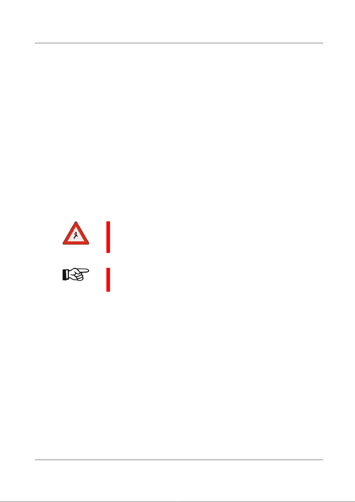
1.2 Safety information and tips
The following symbols are used in these operating instructions:
DANGER!
This warns against dangers to persons. These sections provide you
with information on what to do and what not to do in order to prevent
personal injury.
WARNING!
These sections indicate possible damage to the test system. They pro-
vide information on what to do and what not to do in order to prevent
damage to property.
NOTE!
These sections provide tips for the user on how to use the system bet-
ter and also provide other useful information.
1.3 Use as intended SAFETY
26.452
1.3 Use as intended
The sensor system is suitable only for non-destructive testing of round
material.
Diameter range: see 2.4 Technical Data
Smaller diameters and larger diameters may not be admitted into the
sensor system under any circumstances.
Material with a cross-section which is anything other than round may not
be admitted into the sensor system under any circumstances.
The sensor system may be operated only in conjunction with a suitable
conveying mechanism and a lifting table.
On no account may you convert or modify the sensor system arbitrarily,
for reasons relating to safety.
DANGER!
Masses rotating at high speed pose a serious danger to your life if the
machine is operated incorrectly.
Never touch the rotating sensor components.
NOTE!
The information on operation, servicing and maintenance prescribed in
these operating instructions must be followed strictly.
1.4 Dangers posed by accessories
Transport mechanisms, lifting table and external control equipment must
not render the protective safety devices of the sensor system inoperable.
1.5 Emissions
See 2.6 Environmental conditions.

SAFETY 1.6 Danger sources
6.452 3
1.6 Danger sources
The sensor system operates with a rotating test system and an attached
roller guide system during operation. A person coming into contact with
the roller guide or the rotating test system may suffer very serious injuries.
Switch off the drives before you put your hands into or touch the sensor
system. Wait for all motions to cease!
Before carrying out servicing and cleaning work, switch off the drive for
the sensor system and conveying mechanisms and disconnect the power
supply (secure the master switch in position OFF).
Never remove protective safety devices or render them inoperable by
making modifications to the system.
1.7 Workstations
The workstation is located on the electronic equipment cabinet or on the
operating panel of the sensor system
Do not carry out any work or tamper in any other way with the sensor sys-
tem when it is rotating.
1.8 Authorised operators
Only authorised personnel may work on the sensor system.
Please comply with the minimum legal age!
The operator is responsible for the safety of third parties in the work area.
The scopes of authority for the various activities on the sensor system
must be clearly defined and complied with.
Untrained personnel pose a safety risk!
The operator must
make the operating instructions available to the machine operator and
make sure that the machine operator has read and understood them.

1.9 Personal safety equipment SAFETY
46.452
1.9 Personal safety equipment
You are to wear ear plugs, if the A-weighted equivalent sound pressure
level at the workstations of the sensor system is greater than 85 dB(A).
Sound pressure level for this equipment: see 2.4 Technical Data.
1.10 Safety measures at the installation location
The sensor system must be installed stably on a machine foundation pro-
vided for it and must be firmly anchored to the foundation. If this is not
done, this will pose a potentially lethal risk.
NOTE!
Ensure that the area surrounding the workstation is always clean and
unobstructed by issuing appropriate in-company instructions and con-
ducting inspections.
1.11 Protective safety devices
The CIRCOGRAPH sensor system is shut down
when opening the housing (safety switch on the rotor cover)
with the switch on the operating panel or on the electronic equipment
cabinet
with the EMERGENCY-STOP switch on the operating panel
(EMERGENCY-STOP has to be linked with motor control)
The protective safety devices
are installed to ensure the safety of the operating staff
may not be modified, removed or bypassed by making modifications to
the sensor system under any circumstances.
1.12 Behaviour in the event of an emergency
In an emergency, please immediately press the red EMERGENCY-STOP
switch. Have authorised personnel remedy the cause of the fault immedi-
ately.

SAFETY 1.13 Declaration of Conformity
6.452 5
1.13 Declaration of Conformity
DECLARATION of CONFORMITY
Manufacturer: INSTITUT DR. FOERSTER GmbH & Co. KG Phone +49 7121 140-0
In Laisen 70 Fax +49 7121 140-488
72766 Reutlingen info@foerstergroup.de
GERMANY www.foerstergroup.de
Responsiblity for
documentation: Dr. Juergen Schroeder
Product: CIRCOGRAPH® DS Sensor system Ro 65
Type: 6.452
Serial No.: 168 and higher
We declare, that this product complies with the requirements of following European Directives
and corresponding Standards:
• European Directive 2006/42/EC: Safety of machinery
• European Standards EN 12100-1, -2, EN 14121-1, EN 60204-1
• European Directive 2006/95/EC: Safety of electrical apparatus
• European Standard EN 61010-1
• European Directive 2004/108/EC: Electromagnetic Compatibility
• European Standard EN 61326-1
This declaration relates exclusively to the machinery in the state in which it was placed on the
market, and excludes components which are added and/or operations carried out subsequently
by the final user.
Reutlingen, April 14, 2011
Dr. Juergen Schroeder
General Manager - Division Test Systems

1.13 Declaration of Conformity SAFETY
66.452
Notes:

FUNCTIONAL DESCRIPTION 2.1 Application
6.452 7
2 FUNCTIONAL DESCRIPTION
2.1 Application
Non-destructive testing of ferromagnetic, austenitic and non-
ferromagnetic round materials (wires, bars and tubes) for surface flaws in
conjunction with the CIRCOGRAPH®DS testing and evaluation electronic
equipment and a suitable mechanical handling system.
Diameter range of test material 5 to 65 mm
Preferably continuous testing, also separate piece testing
Surface free of scale, wherever possible bright
Testing without physical contact at rotational speeds up to 6,000 rpm
End condition free of projecting burrs
Max. test material temperature +80 °C
Test heads with track width 2.5 - 5 - 10 mm [BS]
Testing capacity
Surface flaw testing, preferably longitudinal flaws
Flaw detectability for bright material surface from flaw depth of approx.
50 µm
Testing speed of up to 4 m/s for gapless testing (rotational speed =
6,000 rpm and two test heads with 2x10 mm track width)

2.2 Mode of operation FUNCTIONAL DESCRIPTION
86.452
2.2 Mode of operation
The sensor system operates on the basis of the eddy current principle in
accordance with EN 12084. Rotating systems are used to detect longitu-
dinal surface defects. Probes rotate at high speed and without physical
contact around the test piece. By feeding the material the probes scan
the surface in helical paths.
Due to the locally high resolution of the probes and the transverse move-
ment across the crack by each revolution, this is the most sensitive
method for detecting longitudinal defects.
Any time a probe crosses a crack, it generates a signal. Thus, the rotating
system generates a high number of consecutive signals that reliably indi-
cate a flaw of a certain length.
The testing speed is a result of the number of rotating probes, integrated
in the rotating head, the track width of all probes, and the rotational speed
(rpm). The helical path of all probes must be side by side to guarantee a
fully gapless scan.
The signals recorded by the probes are transferred from the sensor sys-
tem to the test electronics for evaluation.
The primary power supply and the secondary signal of the probes are
transmitted by rotating inductive transmitters without physical contact.
Signal generation during
rotary testing
Test tracks and flaw signals
of a rotating probe
Test tracks of two rotating
probes offset by 180º
Test tracks of 2x2 rotating
probes offset by 90º
FUNCTIONAL DESCRIPTION 2.3 Construction
6.452 9
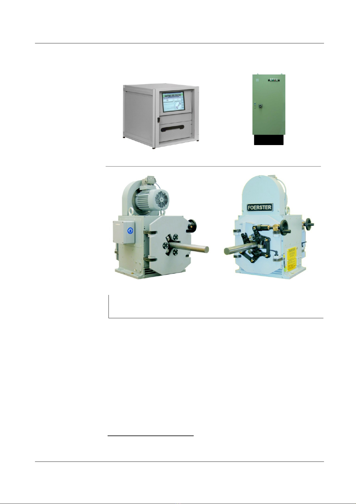
2.3 Construction
CIRCOGRAPH DS test electronics and the connection cables are re-
quired for a complete test system, besides the sensor system*which
scans the test material and generates the eddy-current signal.
A separate leaflet
“CIRCOGRAPH DS System 6.430", Order-No. 163 852 1
will inform you about the according test electronics.
*The procedure for selecting a nozzle and for scale setting has changed
Fig. 2.1 Test equipment configuration,
top: CIRCOGRAPH DS / MOC SB, bottom: Ro 65 entry side / exit side
2.3 Construction FUNCTIONAL DESCRIPTION
10 6.452
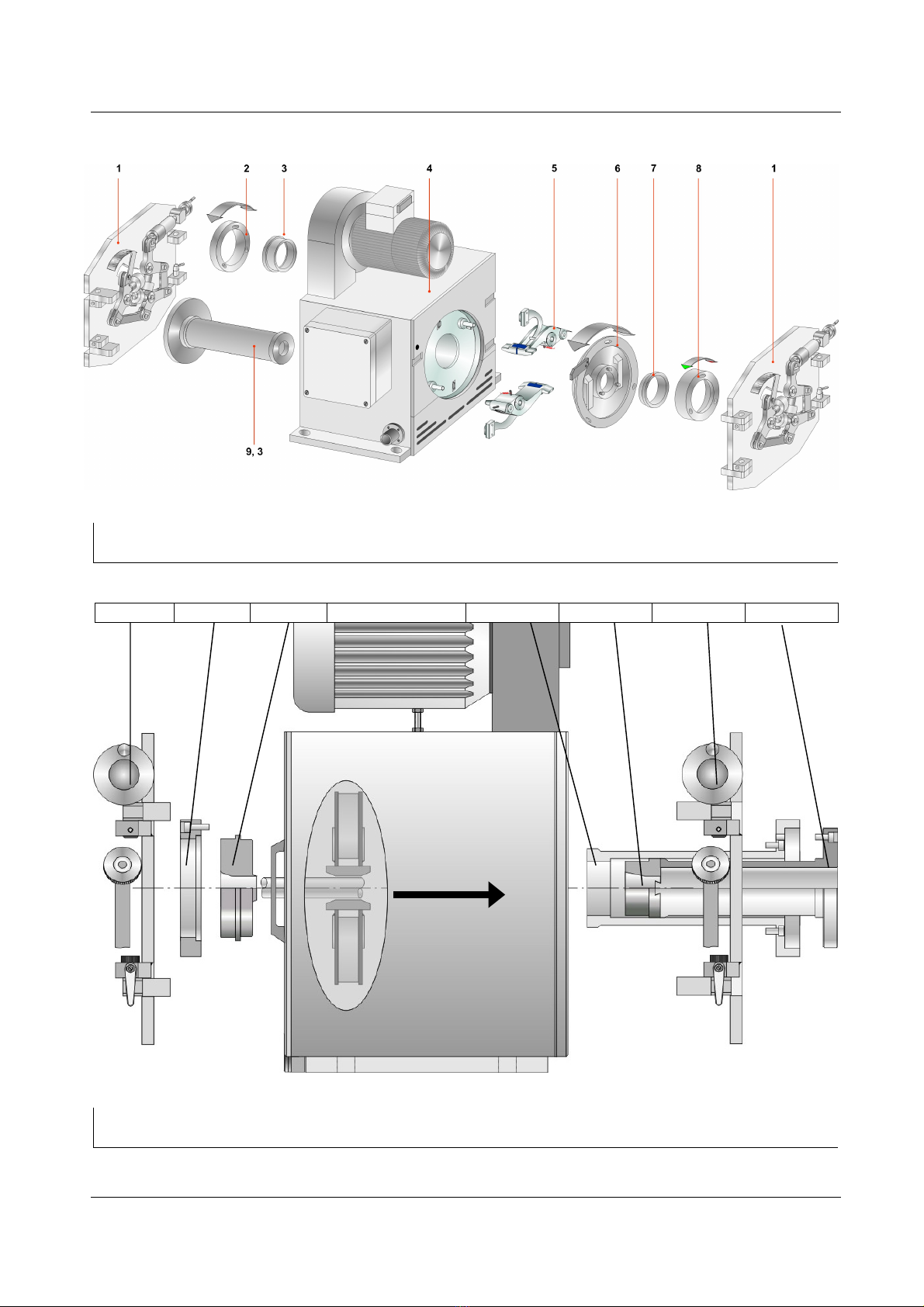
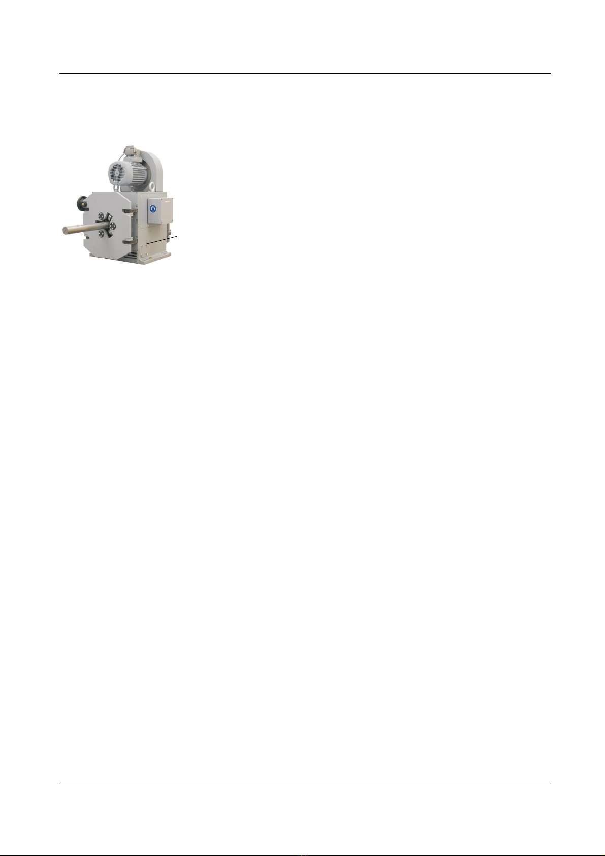
Fig. 2.2 CIRCOGRAPH Sensor system Ro 65, main view, legend ref. to Chp. 2.7
Fig.2.3 CIRCOGRAPH Sensor system Ro 65, basic components
Throughput
Roller guide Clamping ring Entry nozzle Outer sleeve Exit nozzle 5 -30 Roller guide Inner sleeve
FUNCTIONAL DESCRIPTION 2.3 Construction
6.452 11
In order to withstand the rough conditions of use, the rotating head has
been designed to be dust-protected, robust and reliable by means of
complex constructional measures such as labyrinth seals and dirt deflec-
tors.
The chamber surrounding the test zone serves the purpose of contact
and burst protection as well as dust collection. This chamber is provided
to connect an external extraction system (to be provided by customer).
The sensor system consists of the following compulsory components:
Rotating head Ro 65
Test heads
Protective nozzles
The following options are available for adaptation to particular material
conditions:
Centric triple roller guides
Nozzle holder and Nozzle Drawing Line
Nozzle holder and protective nozzles with connector for compressed air
(to keep the testing zone free of dust)

2.3 Construction FUNCTIONAL DESCRIPTION
12 6.452
2.3.1 Test Heads
The test heads are both the heart of the sensor system and its most criti-
cal components.
They consist of an eddy-current probe with field, measuring and clear-
ance windings which are installed in a precise mechanical holder and are
connected by means of a highly flexible special cable with a connection
plug.
As already mentioned in the ‘Mode of operation’ section, there is a
mathematical relationship between the number and track width of the test
heads, the rotational speed and the testing speed.
The following table shows these relationships and gives typical examples
for a practical selection:
Maximum testing speed Test head type
n = 3,000 rpm
n = 6,000 rpm
Number / Track
width TH / BS
Bright material
Fe - Nfe - Aust
rough rolled
Fe
Decreasing
sensitivity to short
flaws
0.5 m/s
1.0 m/s 2 TH / 2 x 2.5 mm 6.452.01-2311 6.452.03-2311
1.0 m/s
2.0 m/s 2 TH / 2 x 5.0 mm 6.452.01-2321 6.452.03-2321
2.0 m/s
4.0 m/s 2 TH / 2 x 10 mm 6.452.01-2331 6.452.03-2331
Tab. 2.1 Test head selection
Rotating disc with test heads
Probe
Test head
Other manuals for CIRCOGRAPH DS
1
Table of contents
Other Foerster Accessories manuals


