dinacell OMEGA NG User manual
OMEGA
/NG
LOAD WEIGHING DEVICE
User manual

User manual OMEGA
/
NG
2
INDEX
1.DESCRIPTION AND MAIN FEATURES ..........................................................3
2.DISPLAY AND CONTROL BUTTONS.............................................................3
3.DIMENSIONS, INSTALLATION AND CONNECTIONS...................................4
4.MENU STRUCTURE ........................................................................................5
5.HOW TO VISUALIZE OR CHANGE PARAMETERS......................................6
6.DEVICE INFO...................................................................................................7
7.SYSTEM CONFIGURATION............................................................................8
8.ALARMS CONFIGURATION..........................................................................10
9.CHAIN COMPENSATION ..............................................................................12
9.1.New Chain Compensation.........................................................................12
9.2.Submenu Chain.........................................................................................12
9.3.Chain Compensation Adjust ......................................................................13
9.3.1.Software Compensation .....................................................................13
9.3.2.Hardware Compensation....................................................................13
9.3.3.Auto-Zeroing Compensation...............................................................14
10.ADDITIONAL FUNCTIONS............................................................................15
10.1.Hold function..............................................................................................15
10.2.Analog output (Optional)............................................................................15
10.3.Cabin Display (Optional)............................................................................16
11.CANOPEN PARAMETERS (ONLY RELEVANT FOR OMEGA-C MODELS )...........16
12.ERROR CODES AND TROUBLESHOOTING ...............................................18
13.ELECTRICAL SPECIFICATIONS ..................................................................18
14.NG CONECTION............................................................................................19
14.1.Wifi NG Connection ...................................................................................19
14.2.Firmware Update .......................................................................................19
15.WIRE ROPE TENSION EQUALAZING..........................................................20
15.1Wire Rope Tension checking Tool.............................................................20
15.2Assistance to the wire rope tension adjustment.........................................21
16.QUICK CONFIGURATION GUIDE.................................................................23
User manual OMEGA
/
NG
3
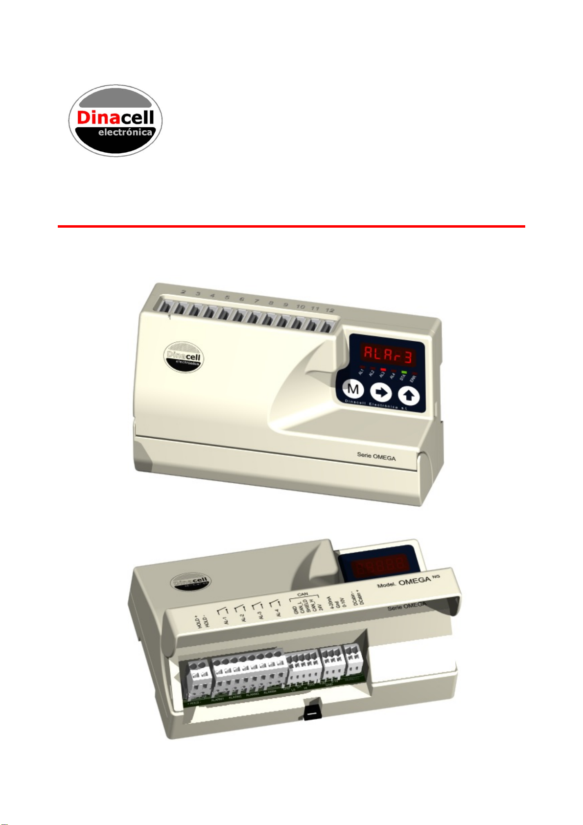
1. DESCRIPTION AND MAIN FEATURES
OMEGA/NG Unit control is a Load Weighing device of the (NG) New Generation units from
Dinacell Electronic with CanOpen-Lift CIA 417 Integrated.
The Main features of this unit are:
-Measures, monitors and limits load in elevators.
-Up to 12 Individual Rope Tension monitoring.
-Wire Rope Tension adjustment.
-5 Digits display with 4 LEDs for alarm indication and 2 LEDs for Can Status
-Hold Input
-4 Alarms Thresholds (Full Load, Over Load, Zero Cabin, Slack Rope Tension )
-4 Relays output
-0-10v Analog Output
-4-20ma Analog Output
-Cabin Display Output
-CanOpen-Lift CiA 417.
-Software Chain compensation.
-Hardware Chain compensation.
And the new features of Our NG devices
-Remote WIFI Programming( NG )
-USB connection for firmware upgrading.
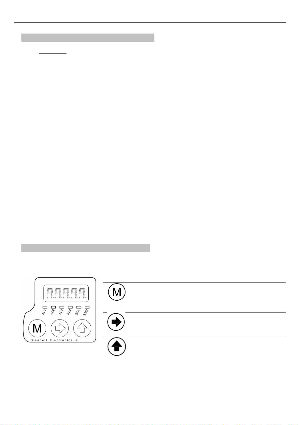
2. DISPLAY AND CONTROL BUTTONS
Functions of control buttons:
The unit is equipped with a menu by which the individual setting
parameters can be displayed or modified.
a. By Pressing this key for 2 Seconds Enter/exit the menu
b. By Pressing this key inside the menus will navigate through
parameters.
c. Accept and save modified values when modifications are on
progress.
a. During menu navigation: Enter to modify a parameter.
b. While modifying a parameter: Chose digit to change.
a. During menu navigation: Show the stored value of the selected
parameter.
b. While modifying a parameter: Change the blinking digit
incrementally from 0 to 9.
User manual OMEGA
/
NG
4
Note: After two minutes without any operation, the unit automatically returns to the total weight measure
display, independent of the menu item previously selected.
Led Functions
AL1 Full Load Alarm Indicator
AL2 Over Load Alarm Indicator
AL3 Zero Load Level Indicator (Empty Cabin)
AL4 Slack Rope tension indicator
STA Led status ( For CanOpen: Status Led )
ERR Error ( For CanOpen: Error Led)
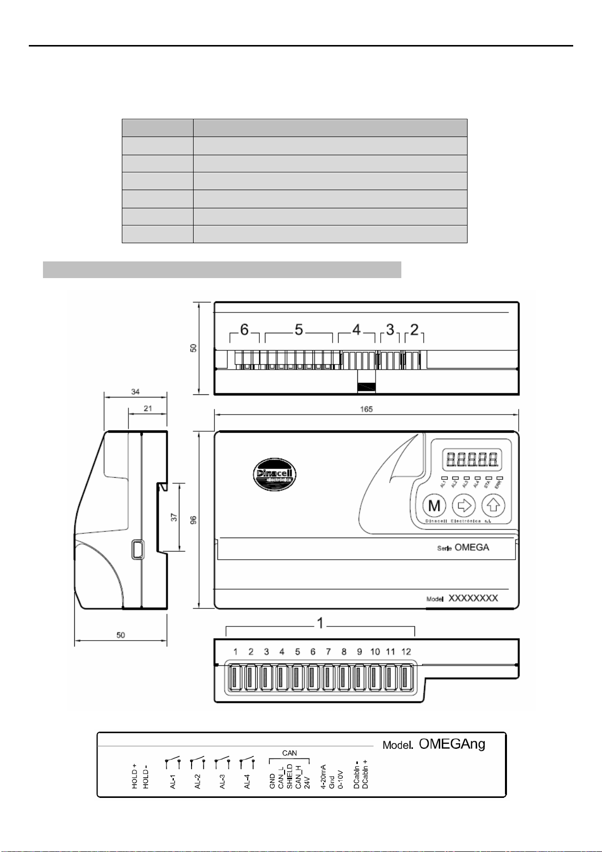
3. DIMENSIONS, INSTALLATION AND CONNECTIONS
User manual OMEGA
/
NG
5
1Sensor inputs Up to 12 USB Connectors for easy plugging
2Cabin display
output
Output It provides two types of output:
INC: Progressive display MB-D (two wire connection without
polarity).
LED: If overload, it will be an intermittent voltage of 5V (max. 30mA)
with the polarity shown in the figure.
3Analog outputs This output reflects the sensors signal over the range 0-10V and
4-20mA. Common signal is GND. (See the ADDITIONAL FUNCTIONS chapter).
4Can Open Input 24 VDC power supply and Can Bus in an Open Style connector
5Relay
connections for
alarms
Terminals of the alarm relays.
(See the alarms section in chapter 8)
6HOLD input This function will be activated if an input voltage from 24 to 230V (DC or AC) is
applied. (See the ADDITIONAL FUNCTIONS chapter).
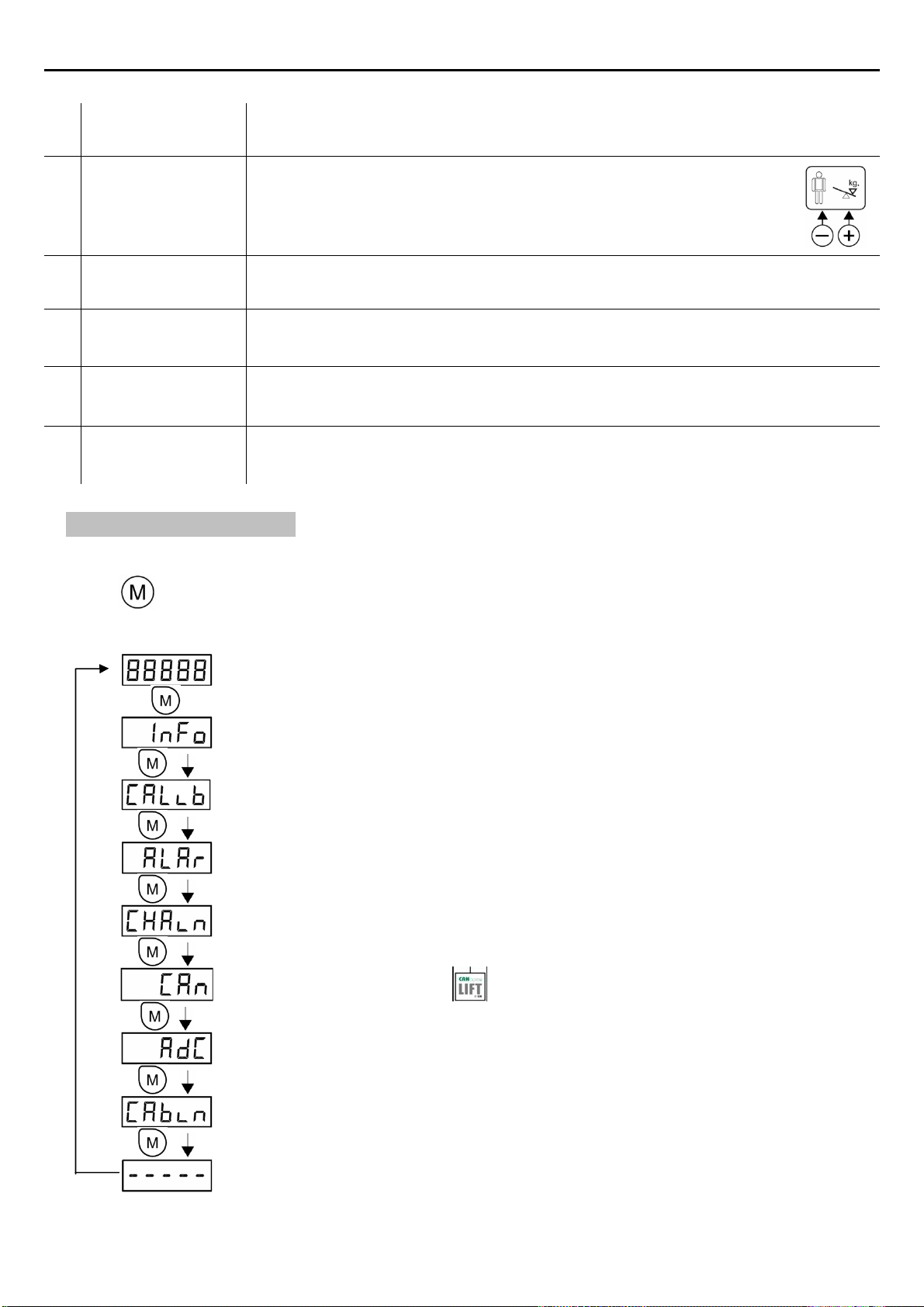
4. MENU STRUCTURE
The menu has the cyclic structure shown in the following figure.
Press button for 2 seconds to enter and then press it repeatedly to move from a parameter to
another. Press it for 2 seconds to exit.
Weight indication. Display the value of the measured load
Press Menu for 2 Seconds
Shows Identification Data of the unit
System calibration. These menus shows all parameters related with the load cell
Configuration.
Alarm Levels configuration.
Chain compensation options
CanOpen Configuration.
(Only relevant for OMEGA-C models )
Load Cell mv/v. signal value.
Led or Cabin Display Output
(Only relevant for OMEGA-4RM models )
Pressing Menu for 2 seconds inside the internal navigation menu will end the menu navigation and
return to Display the value of the measured load

User manual OMEGA
/
NG
6
5. HOW TO VISUALIZE OR CHANGE PARAMETERS
Once inside any menu and displaying the parameter to be viewed or changed:
Press to display the current value.
Press to select the parameter to be modify :
Press to choose the digit position to change ( Flashing )
Press to change the value of the Current Flashing digit position. (if there’s no flashing digit,
change the value with key directly)
Press twice to save the value.
If button is not pressed again before display Flashing ends (10 seconds), the
parameter value will not be changed.
After any of these operations, the display will show the current parameter.
User manual OMEGA
/
NG
7
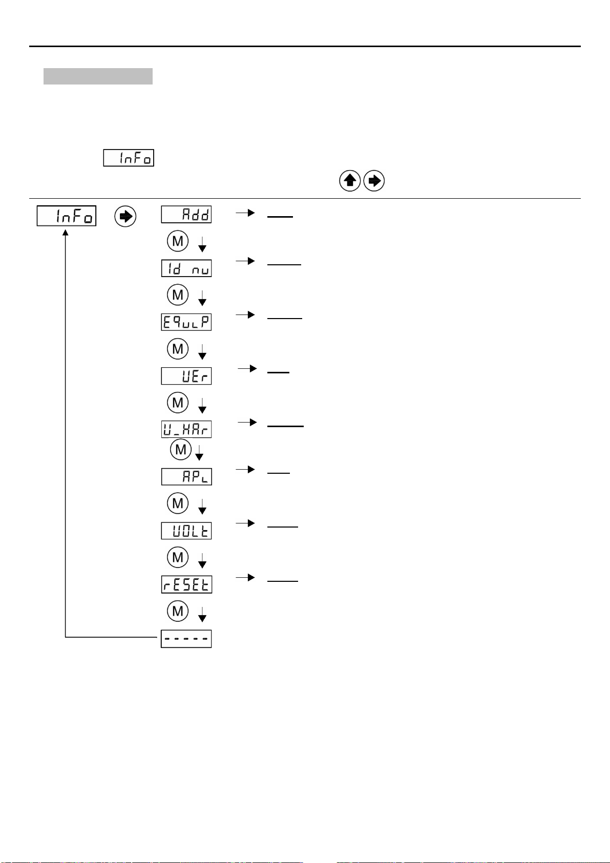
6. DEVICE INFO
All new NG units store some important information in this menu in order to build wireless
connections with any remote future unit developed by Dinacell Electronica. All parameters can be read in
this submenu.
Submenu
Press to enter Check value Enter to modify
Add: NG Network Address of the unit.
Id_nu: Identification number of the unit. Unique identification
for each unit.
Equip: Model of unit.
Valid Values: OME
Ver: Firmware Version of Unit OMEGANG
Valid Values: 1.00 and above
V_Har: Hardware Version of Unit OMEGANG
APi: ApiVersion of NG Dinacell Network
Valid Values: 100 and above
VOLt: Internal Power supply Voltage of unit OMEGANG
Valid Values: (around 24 volts )
rESE: Reset all parameters value to Factory defaults. All
calibration data will be lost
User manual OMEGA
/
NG
8
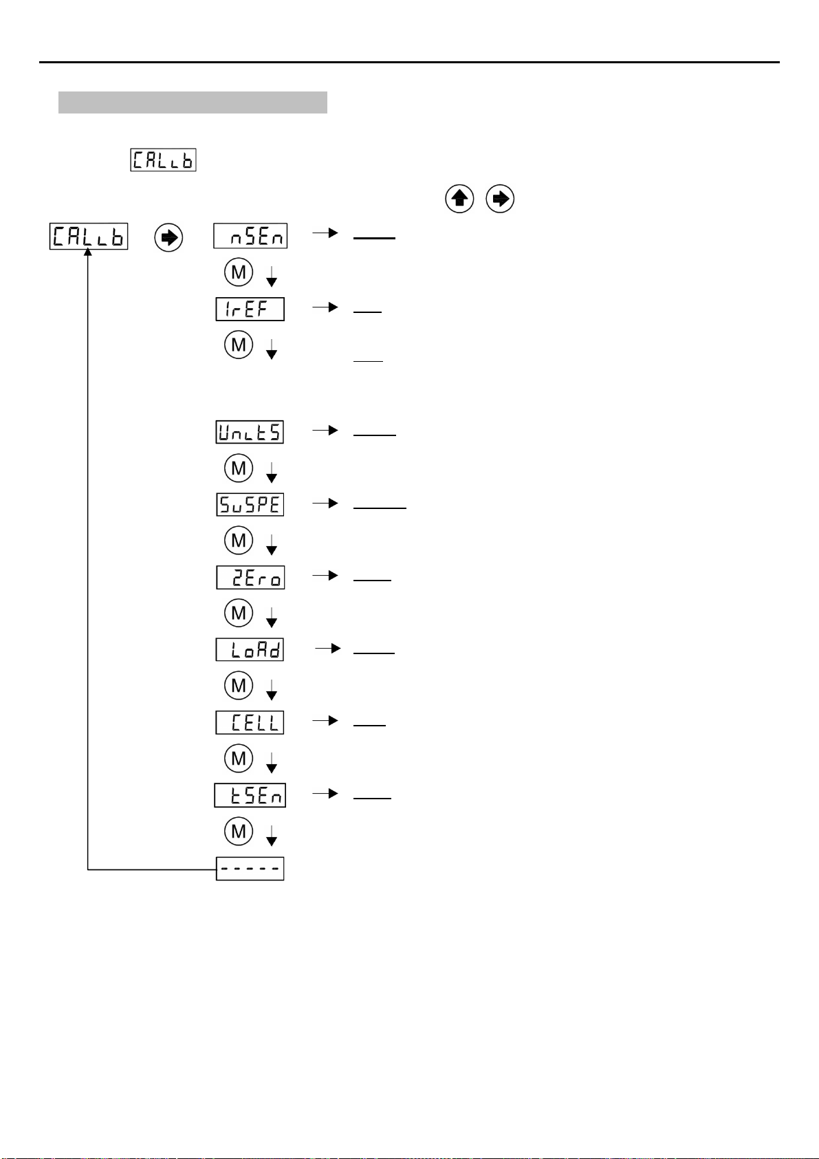
7. SYSTEM CONFIGURATION
This section describes how to configure the Unit to obtain the best measure accuracy. The configuration
is done in Menu.
Press
to enter Check value Enter to modify
nSen: Number of sensors connected to ropes or cables. If this
parameter is not set correctly, the unit will show Err1 and
alarm relays will be activated.
Iref: Initial Reference of the sensors. This operation must be
done with the Sensors uninstalled on the ropes.
Note: It is mandatory to do the iref operation if Wire Rope Tension
balancing is going to be adjusted.
If you forget to make this operation or no rope tension equalizing
needs to be performed, you can select the option “rese” on Iref Submenu to
make the iref with sensors installed.
Units: Display Weight units. Available units are Kilos/Pounds
SusPE: Type of suspension at installation:
1:1 2:1 3:1 4:1
Zero: Zero point adjustment With empty elevator. Store a
Countdown value for Zero and load calibrating parameters
Load: Well known weight applied inside the elevator to do the
weight calibration of the unit. (It is recommended to set up to
60% of the nominal load of the elevator.)
Cell: Nominal load cell sensibility. This value is calculated
when LOAD operation is done. User shouldn´t modify this
value. ( If this parameter is modified the previous calibration
settings will be overwritten)
tSen: indication of individual Sensor Rope weights. On the
display appears the weight in units selected (e.g. 100kg)
alternating with the Sensor number ( Se 1)
User manual OMEGA
/
NG
9
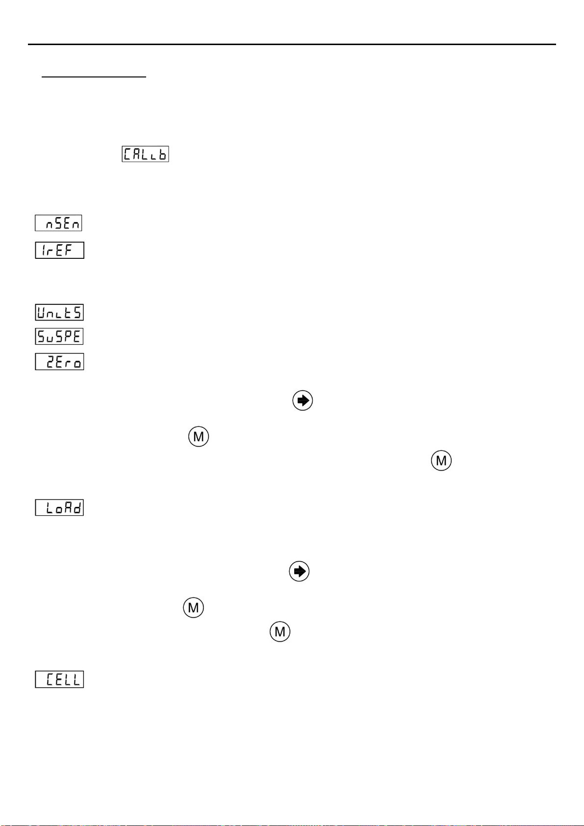
Calibration process:
1) Install the control unit with the information of the INSTALL AND CONNECTIONS chapter.
2) Connect Load Cell to the OMEGANG
3) Power up the unit with the correct voltage (see the ELECTRICAL SPECIFICATIONS chapter).
4) Go to Submenu:
5) Detail Calibration Procedure:
Follow next steps to set a precise Load Measuring system
5.1 ) Select number of sensor ropes.
5.2 ) Do and Iref “ALL” Operation with sensors not installed on the ropes.
Note: if your sensors are already installed and you don’t need to equalize the rope tension
you can select “rese” option on Iref submenu.
5.3 ) Select display measuring units. Available units are Kilograms or Pounds
5.4 ) Select Suspension. By default 1:1 is selected
5.5 ) Zero adjustment:
a) Install sensors on the ropes when using SWK, SWR or LCA.
b) Select Submenu Zero by pressing
c) Change countdown value if desire.
d) Press menu and display will start flashing
e) Make sure elevator is empty and confirm operation by pressing again.
f) The countdown will start. During this time, the car weight must not change.
5.6 ) Load Point adjustment: With This function the Unit will be calibrated with the best
accuracy.
Put a well known weight into the cabin. Is recommendable a 60% of elevator duty load.
To make the Load point adjustment:
a) Select Submenu Load by pressing
b) Set the value with the total Load added into the elevator.
c) Press menu and display will start flashing
d) Confirm operation by pressing again.
e) The countdown will start. During this period of time, the car weight must not change
5.5) This parameter stores the Sensor Sensibility. Cell value is automatically calculated after a
Load Point adjustment. If Cell Value is changed, the previous calibrating process will be
overwritten.

User manual OMEGA
/
NG
10
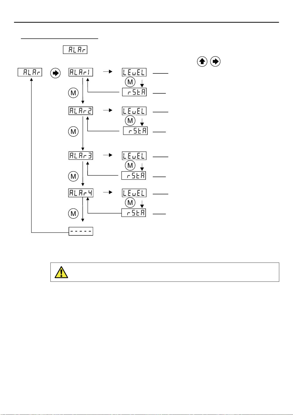
8. ALARMS CONFIGURATION
The alarms values correspond to the load threshold at which each relay change its state.
The relays allows to be configured individually as make or break contact
Alarms are activated when their threshold is exceeded. The Unit OMEGANG has 4 different alarms:
AL-1 (Full Load, Relay #1):
Change of state when exceeding the load programmed in
AL-2 (Over Load, Relay #2):
Change of state when exceeding the load programmed in
AL-3 (Zero Load, Relay #3):
Change of state when falling below the load programmed in
Note: This alarm is active below Alarm3 Threshold.
AL-4 (Rope Tension Difference and Slack Rope Tension, Relay #4):
Change of state if any rope has a slack rope tension or if any rope deviates from the average of all
other ropes at least by the percentage programmed in .
The working procedure of the relays as a make or break contact can be changed for each alarm output
using the parameter. Valid values are (Close) for the operating mode MAKE and (Open)
for the operating mode BREAK.Close is a normally closed relay and OPEn is a normally open
relay. Alarm LEDs indicators will be activated when the display measured value overload corresponding
alarm level
Note:LEDsarenotrelatedtorelaystatebutalarmslevels.
User manual OMEGA
/
NG
11
How to configure alarm settings:
Go to Submenu
Press
to enter Check value
Enter to modify
Level: Alarm 1 Level Threshold for Full load
alarm.
rStA: Relay Status. When alarm 1 is deactivated
(Idle Mode) (Only relevant for OMEGA-4R models )
Level: Alarm 2 Level Threshold for Over load
alarm.
rStA: Relay Status. When alarm 2 is deactivated
(Idle Mode) (Only relevant for OMEGA-4R models )
Level: Alarm 3 Level Threshold for Zero Load
alarm.
rStA: Relay Status. When alarm 3 is deactivated
(Idle Mode) (Only relevant for OMEGA-4R models )
Level: Alarm 4 Level percentage Threshold for
Rope tension difference and slack rope alarm.
rStA: Relay Status. When alarm 4 is deactivated
(Idle Mode) (Only relevant for OMEGA-4R models )
All Displayed weights and alarm thresholds are shown in selected units. All
internal calculations are made in kg, therefore, rounding errors are
possible
User manual OMEGA
/
NG
12
9. CHAIN COMPENSATION
9.1. New Chain Compensation
The New Generation of Load Weighing Devices has the newest Software for chain
compensation. It offers several options to improve the accuracy to compensate the weight of the chain.
In this Submenu, the user can choose between three options, no compensation, software
compensation and hardware compensation.
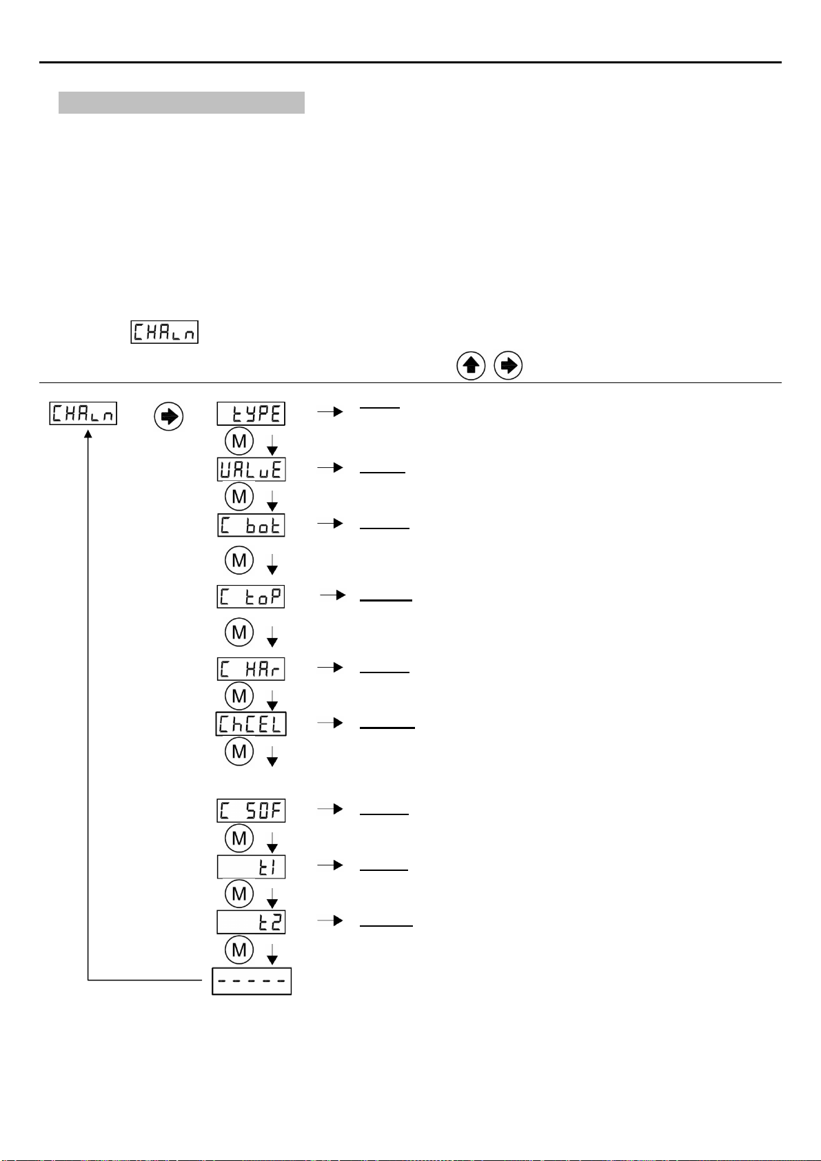
9.2. Submenu Chain
Submenu
Press
to enter Check value Enter to modify
Type: Type of chain compensation applied. User can choose
between hardware compensation, software compensation or
none compensation
Value: Max Chain value to compensate. At installation.
Valid Values : 0-600
C_Bot: Chain zero operation at the ground floor
C_Top: Chain load operation at the top floor
C_Har: Real chain load value compensated by hardware
measure in selected units
ChCEL: Nominal Chain load cell sensibility. This value is
calculated when C_Bot or C_top operation is done. User
shouldn´t modify this value. ( If this parameter is modified
the previous calibration settings will be overwritten)
C_Sof: Chain load value compensated by software
estimation in selected units
Time 1: Time to get hold weight before Hold is activated
Time 2: Time to get hold weight after Hold is deactivated
User manual OMEGA
/
NG
13
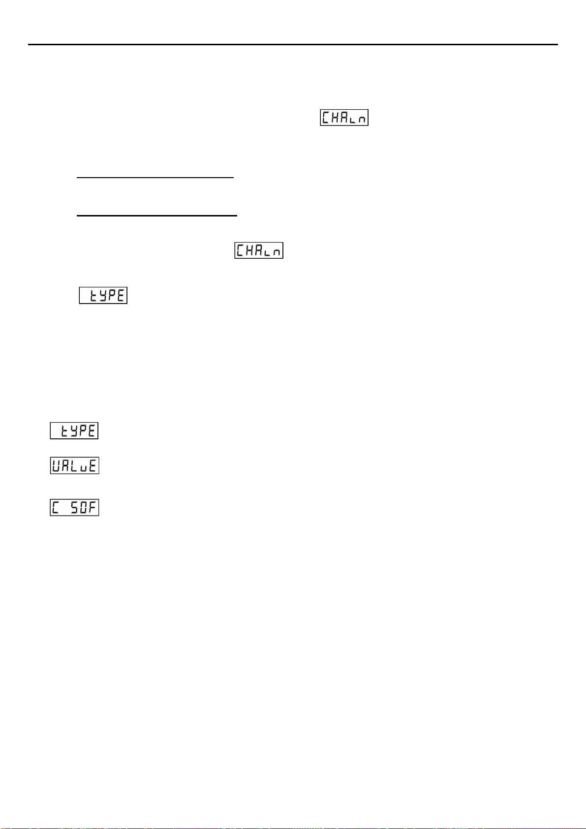
9.3. Chain Compensation Adjust
The NG Series has new advanced chain compensation. To use all the features of new
compensation is necessary to adjust some parameters in Menu.
There are two types of compensation.
Software chain compensation: When selected, the unit compensate the chain with hold signal
activations/ deactivations.
Hardware chain compensation: When selected, the unit compensate the chain with the on real
time weight of the chain. This can be done using the auxiliary Load Cell input for chain
compensation and adjusting the parameters for hardware compensation.
Note: To deactivate all chain compensations just set Type parameter to none.
Set Type to None value.
9.3.1. Software Compensation
This function allows compensate the difference of weight between floors produced by the
chain. The unit needs the HOLD signal to be active when the doors close to compensate the
weight during the elevator movement.
To configure the software compensation:
Set Type to SoFT value.
Set the estimated weight of the chain. This parameter will be the maximum value
compensated by software compensation
In this parameter you can check the value the OMEGANG is compensating by software each
time the HOLD signal is deactivated
When using software compensation, Auto_Zero compensation will be activated automatically.
9.3.2. Hardware Compensation
In some installations ( the largest ones), software chain compensations doesn`t work
perfect due to different friction in the rails between floors, weight changes during long
elevator travels, or just any auto_zero is done cause elevator never stops.
These problems can be solved with Hardware compensation.
It is mandatory to plug an auxiliary Sensor (Load Cell for chain compensation)
when hardware compensation is selected. Otherwise Err11 will flash in the display.
Auto_Zero compensation will be also deactivated automatically
A system Configuration (Point 7) must be done previous to set the Hardware compensation
parameters.

User manual OMEGA
/
NG
14
Set Type to Hard value
Take the elevator to the ground floor and set C_Bot To Yes. A Countdown will
start.
Take the elevator to the Top floor and set C_TOP To Yes. A Countdown will start
In this parameter you can check the value the OMEGANG is compensating by hardware
with the chain load cell
9.3.3. Auto-Zeroing Compensation
The Auto_Zero compensation is designed to automatically remove small measurement error
lower than parameter
The Auto-Zero function will happen whenever the OMEGANG measures a static offset of ±
for a period of at least 120 seconds. During this time the measured load must not change
by more than 20kg. The OMEGANG applies an internal compensation value equal to the inverse value of
the currently measured offset.
The Auto_Zero compensation value is stored in internal memory. After power cycling the measure in
the display will be the same. To eliminate the Auto_Zero compensation, a Zero operation should be
done.

User manual OMEGA
/
NG
15
10. ADDITIONAL FUNCTIONS
10.1. Hold function
During the elevator travel, the measured loads can heavily fluctuate due to friction in the rails,
loads movements, etc. When a voltage in the range 24-230V (DC or AC) is applied in this input, the unit
holds the last stable measure of weight acquired.
The voltage must be applied when the doors close and it must be removed as the doors open.
This ensures that the movement of the cabin will not affect the weighing process and therefore, no
alarms or relay will be activated during elevator travel.
To improve the hold of a stable measure two parameters have been added at CHAIN menu
and .
As some installations sets the HOLD input at the same time it closes the doors, sometimes the
last measure obtained is not as stable as desire. The same issue can happen when removing the HOLD
input and the doors Open.
Time in tenth of seconds to take the measure before the hold. Signal is active.
Time in tenth of seconds to update the measure after the hold. Signal is released.
Note: With T_1 = 10 and T2 = 15:
If hold signal is activated, then, the OMEGANG will take as a valid measure the last stable weight
value that was stored 1 second before hold was activated. Then when hold is released the first stable
value will be taken 1.5 seconds after the hold signal is deactivated.
This option offers great flexibility to resolve problems in some critical installations.
10.2. Analog output
(Optional)
This unit is provided with two analog outputs (Voltage and current output). Both Outputs are
active and operative at same time.
This function reflects the sensors signal over the range between ZERO and the value sets for
ALARM1 (full load):
Output Range
0-10 volts
( 0-5 Optional )
When weight ≤0kg
(empty elevator) 0 V
When weight ≥ALARM1
(elevator at full load)
10 V
( 5V Optional )
4-20 mA
When weight ≤0kg
(empty elevator) 4 mA
When weight ≥ALARM1
(elevator at full load) 20 mA
User manual OMEGA
/
NG
16
Example: Once the system is completely configured, if ALARM1 is set to 400 kg and if unit measures
200kg then;
0-10V Output will be 5V.
4-20mA output will be 12mA.
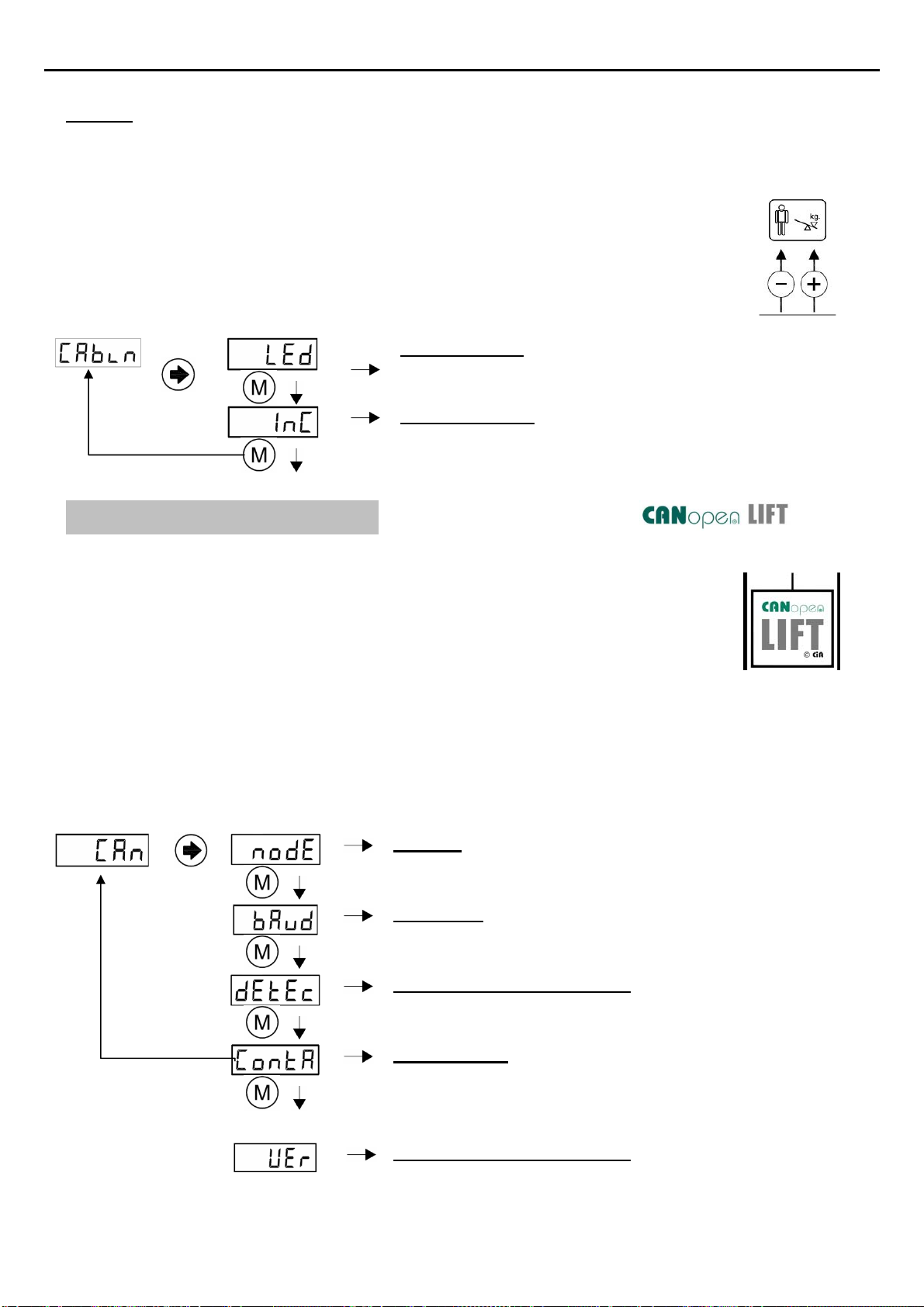
10.3. Cabin Display
(Optional)
It provides two types of output depending on the CDISP parameter:
LED Indicator: Under overload it will be an intermittent
voltage of 5V (max. 75mA) with the polarity shown in the
figure.
LED Incremental Progressive display MB-D (two wire
connection without polarity)
11. CanOpen PARAMETERS (Only relevant for OMEGA-C models )
Dinacell electronic is member of the CiA ( Can In Automation ),
Vendor-ID 00000361
OMEGANG-C accomplish with the CanOpen-Lift CiA 417 profile.
Some important CanOpen Parameters can be modified from this Submenu as, Baud rate and
Node ID. Weigh change detection is a threshold that will send a PDO message when the weight
change overpasses the value.
Node Id: Node Id of the CanOpen Load Weighing Device
Baud Rate: Baud Rate of the CanOpen Device.
125kb or 250kb Supported for the 417 Profile.
Detection of weight change: Units required for detecting a
change of weight in the cabin and send a Can Message by
load changed. (1,2,5,10,20,25,50,100,250)
Door Contact: If a Car Door Unit is present at the installation,
the OMEGANG-C can Read the Door status just setting this
parameter to “Yes”. When the Door closes the Measure on
the Display is Hold and it will not change until the door Opens.
.
CanOpen Version supported: Actual version supported 2.0.0

User manual OMEGA
/
NG
17
CanOpen Specifications
FEATURES
NMT NMT Slave
Error Control Node guarding
Life guarding
Heartbeat consumer
Boot-up Yes
Node ID range From 1 to 127
Node ID Proprietary
LMT-services
Keyboard
CanOpen bit-rates 10 kbit/s
20 kbit/s
50 kbit/s
125 kbit/s
250 kbit/s
500 kbit/s
1000 kbit/s
Type of bit-rate adjustment Proprietary
LMT-services
Keyboard
RPDOs 1
TPDOs 1
PDO modes Synchronous (cyclic)
Synchronous (acyclic)
Event-triggered
Remotely-requested
Triggered by event-timer
PDO linking Yes
PDO mapping Static
SDO server 1
SDO client No
Emergency Producer Yes
Emergency Consumer Yes
Sync Producer No
Sync Counter No
Time stamp No
Additional Functions None
Supported application layer CiA 301 V 4.2
Supported Frameworks CiA 303 V 1.3
Device Profiles CiA 417: CanOpen
application profile for lift
control systems V2.0.0.0

User manual OMEGA
/
NG
18
12. ERROR CODES AND TROUBLESHOOTING
When the unit detects some anomaly it will show an error code from the following table:
Error description Action
Load cell is not properly connected, or its
cable is damaged. Err1 is shown alternating
with the Sensor number ( Se-1,Se-2, etc..)
Check the indicated sensor
connection.
Negative overflow. The load cell is giving a
too high negative signal.
Check the load cell connection. It
should be no negative charge.
Positive overflow. Load cell is holding a higher
load than its nominal value.
Change the load cell by another with
higher nominal load.
Loss of data in memory.
Notice: When this error appears, relays will
change to ACTIVATE state.
The unit must be reset to its default
values
Load cell with very low sensibility. The unit
was not properly adjusted or load cell has a
low nominal value.
Adjust the zero and Load again.
Change the load cell by another with
lower nominal load.
Load cell is not properly connected, or its
cable is damaged, or wrong number of
sensors set in parameter nSens.
Check the chain load cell connection...
If no Hardware chain compensation
desired, change Type parameter at
menu chain to None or soft
Important: When an error appears, all alarms are activated and the elevator
remains blocked.
RESTORING THE FACTORY SETTINGS (Only in case of configuration problems)
Just go to menu and set option to yes:
13. ELECTRICAL SPECIFICATIONS
Power supply characteristics Short-circuitable.
It is not necessary to replace any fuse.
Nominal voltage 10-40 Vdc
Maximum current <200mA
Relays Contacts
(Nominal Switching Capacity) 4 Relays: 250VAC / 3A - N.O.
HOLD Input 24V-230V AC/DC
Box IP-50 V0 fireproof plastic.

User manual OMEGA
/
NG
19
14. NG CONECTION
All New Dinacell Units have a special feature called NG Connection (New Generation
connections)
The main function of the NG connection is to connect to android Smart phones for Unit
calibration, and reading Pen Drives for software updating.
14.1. Wifi NG Connection
To use all advanced features of NG Connection, user needs to
connect the WRCTNG adapter to the unit OMEGANG and Dinacell
TOOLS Application software must be installed in a smart
Phone or Laptop.
Users can download the Dinacell Application “Weighing NG”
from Google Play Store market or from Apple Store.
With the New WRCTNG adapter connected to the NG
Connection of the OMEGANG,users can:
a) Get all parameter values of the unit in real time.
b) Calibrated the unit without using the key board.
c) Test the installation performance.
d) Make studies of the measures in the installation to adjust
rope tensions, guides, detect friction problems during
travels.
e) Save all Calibrating parameters data in a Pdf report.
f) Send reports by mail.
g) Stores all installation calibrations in a single phone.
h) And so on, cause software is in continuous development.
14.2. Firmware Update
It is possible to update the firmware of any NG Device using the NG connection and a Flash Pen
drive.
Follow next steps to enter in Boot loader mode for firmware updating:
a) Copy new firmware (.CYP file) in the Flash Pen drive.
b) Plug the Pen drive in the auxiliary USB cable adapter from USB to Mini USB.
c) Switch off the unit OMEGANG by removing the power supply.
d) Press key and apply power to the unit with the key pressed. ERR LED will flash each
second, and 5 Digits display will be switched off.
e) Plug the Mini USB cable on the NG connector. STA LED Will be ON and ERR LED will Flash
Faster (each 0.5 second)
f) Be patient and Wait until unit reboots. The process can take up to a minute.
g) When programming ends the Unit Will reboot automatically.

User manual OMEGA
/
NG
20
15. WIRE ROPE TENSION ADJUSTMENT
This section explains how to check the tension of all wire ropes of the installation. All ropes
should carry the same tension. Equally tensioned ropes improve ride quality and extend life of ropes and
sheaves.
Nowadays most elevator systems have multiple wire ropes attached to the cabin and
counterweight. This ropes normally run over a traction sheave or pulley just to move the cabin up and
down the hoistway.
When some ropes have more tension than other, the ropes with lower tension will slide over the
pulley and can produce a crown groove wear at the sheave. It is possible to detect this wear by rope
slapping, vibrations on the cables, or metal dust on the pulley.
Normally, the system works better if all the ropes have similar tension (about ± 5%) of the
nominal load of the installation.
Although some installers manage to adjust the rope tension manually just touching the ropes or
Just tuning the installation plucking each rope as a harp string, the best way to do this operation is
measuring the load on all the ropes and displaying it in real time.
Usually Load weighing devices manufactures have dedicated and expensive tools to do this
operations.
But the OMEGANG,can be used not only as a good Load Weighing device but as an additional
low cost rope tension balancing tool also.
And as the unit will be installed for life you will have a permanent tool to adjust wire rope tension
and detect slack ropes at the installation in real time.
15.1 Wire Rope Tension checking Tool
The only tool needed to adjust the wire rope tension is the WRCTNG dongle and a Smartphone a
tablet or a laptop. Then from the rope tension screen you will visualize the load of each rope in real time
Now it is possible to adjust the tension of each rope to make then equal.
Table of contents
Other dinacell Accessories manuals

Popular Accessories manuals by other brands

Benchmark Scientific
Benchmark Scientific Iso-Block BSH6000 Operation manual

Firecraft
Firecraft FBK-100 installation instructions

Baumer
Baumer UNDK 20N6914/S35A manual

Honeywell
Honeywell RPWL303A instruction manual

Bray
Bray 54 Series Installation, operation and maintenance manual

Cisco
Cisco MAS-7513-FAN Replacement instructions


