TIGA T8503 User manual

2L-7120-00
OWNER'S
MANUAL
MODEL NOS.
T8503
READ THESE
INSTRUCTIONS
CAREFULLY!
CAUTION
Tools Needed: nTwo 7/16 Open \ Boxed End Wrenches nTwo ½ Wrenches
nTape Measure nTwo 9/16 Open \ Boxed End Wrenches
Hardware Identifier
(NOTE: This hardware shown actual size. For specific information, see Product Parts List on back.)
26
8 pieces
27
8 pieces
22
4 pieces
28
20 pieces
20 8 pieces
23
4 pieces
31
2 pieces
29
2 pieces
30
2 pieces
25
4 pieces
19
4 pieces
18
8 pieces
4 pieces
17
1. ATTACHING LEGS TO TABLE TOPS
CAUTION
AT LEAST TWO ADULTS ARE NEEDED TO
COMPLETE THE FOLLOWING STEPS!
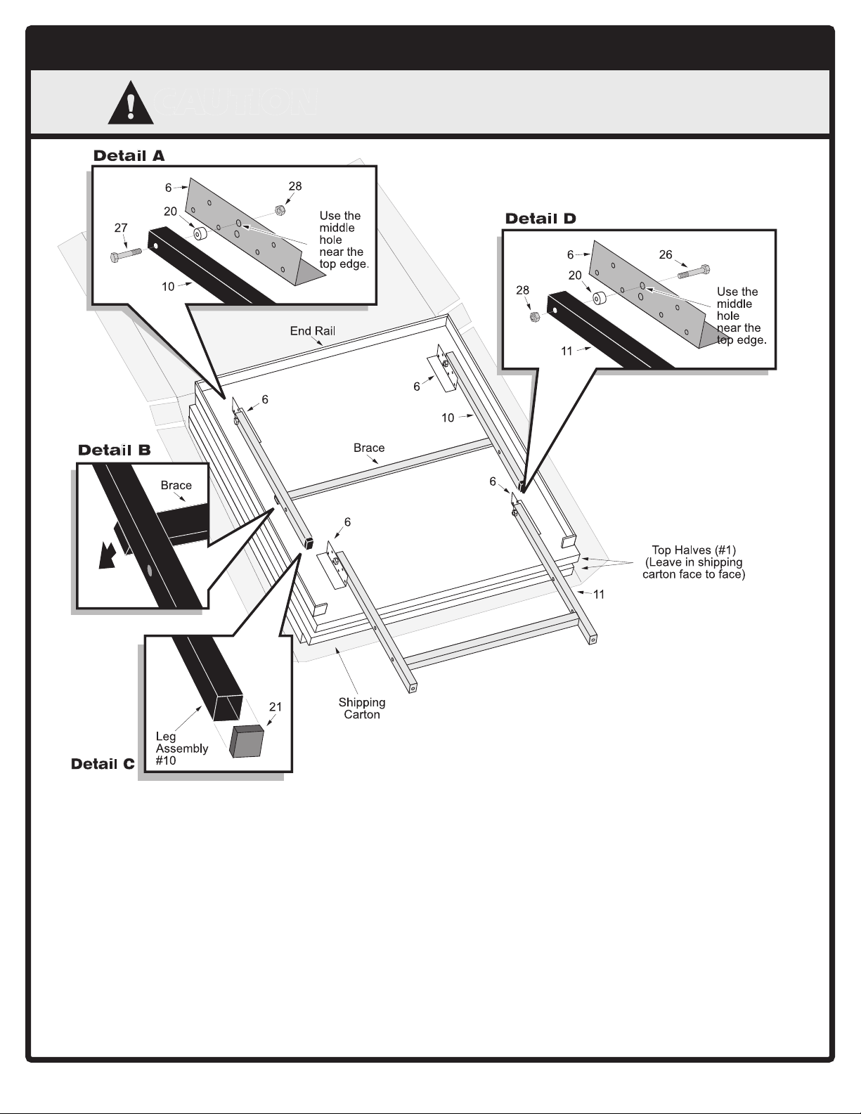
1. Leave top halves #1 in shipping carton as shown
above or lay them on a carpeted floor (to protect
them from damage and scratches ).
2. Attach leg assembly #10 to brackets #6 located
on the bottom of the first top half #1. (See above).
Use bolts #27, spacers #20 and locknuts #28.
(See Detail A).
NOTE: Be sure brace on leg assembly #10 is
against table. (See Detail B).
Tighten these locknuts snug but DO NOT
OVERTIGHTEN THEM. JOINT MUST MOVE!
3. Put caps #21 on bottom end of leg assembly
#10. (See Detail C).
4. Attach upright assembly #11 to remaining
brackets #6 on the bottom of the first top half #1.
(See above). Use bolts #26, spacers #20, and
locknuts #28. (See Detail D). Tighten locknuts
snug but DO NOT OVERTIGHTEN THEM.
JOINT MUST MOVE!
5. With a helper, set the first top half #1 on its side
against a wall. (Be sure to put a piece of
cardboard, cloth, or carpeting on the floor first to
protect the top's edges. ) Turn the second top
half #1 over and repeat steps 2-4 to assemble it.
2
CAUTION
AT LEAST TWO ADULTS ARE NEEDED TO COMPLETE THE
FOLLOWING STEPS! DO NOT LEAVE TABLE UNATTENDED UNTIL
ASSEMBLY IS COMPLETE!
2. ATTACHING NAME PANELS TO LEGS
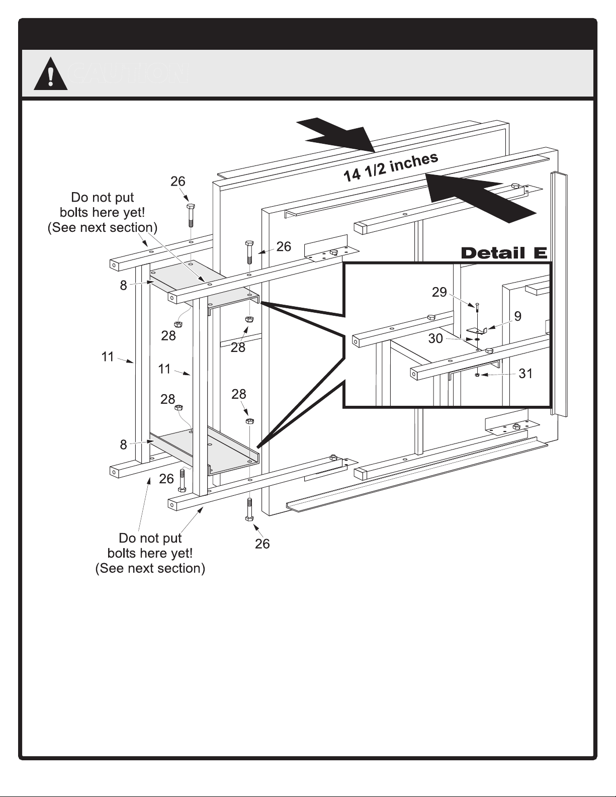
6. With a helper, hold top halves about 14 ½
inches apart. Attach only one half of name panels
#8 to upright assemblies #11 as shown above.
Use ONLY TWO bolts #26 and locknuts #28 on
each name panel.
(Two other bolts #27 and nuts #28 will be used in
the next section to attach the other half of the
name panels and linkages #24 at the same time.
See next page. ) Do not tighten these locknuts
completely tight yet.
HELPFUL HINT: Start at the bottom and insert
two bolts #26 UPWARD through upright
assemblies #11 and name panel #8. Then attach
the upper name panel #8. Insert bolts #26
DOWNWARD.
7. Attach safety latches #9 to name panels using
one screw #29, flat washer #30 and locknut #31.
(See Detail E). Attach a safety latch to one
name panel to hold one table half and the
other safety latch to the other name panel to
hold the other table half. Do not overtighten
locknuts. Latches must pivot freely. When
latch is pivoted it must fall back to original
position when released.
3
3. ATTACHING LINKAGE TO LEGS
28
28
28
5
28
18
18
24
28
27
27
27
24
11
11
24
18
18
18
28
22
24
11
10
Detail F
Detail G
22
18
22
10
9. Attach other end of linkages #24 to leg assembly
#10 using bolts #22, spacers #18, and locknuts
#28. (See Detail G). Tighten these locknuts
snug, but DO NOT OVERTIGHTEN THEM.
THIS JOINT MUST BE ABLE TO MOVE!
10.Attach corner protectors #5 to table corners.
Push snap tabs on corner protectors into holes
in rails.
11.Repeat steps 8 - 11 on other top half #1.
8. Attach linkages #24 to upright assembly #11
using bolts #27, spacers #18, and locknuts #28.
(See Detail F).
NOTE: TIGHTEN LOCKNUTS SNUG, BUT
DO NOT OVERTIGHTEN. JOINTS MUST BE
ABLE TO MOVE!
NOTE: If you have trouble inserting bolts #27
through name panels #8, slightly loosen bolts #26
(that you used in the previous section to attach
name panels #8). (See Section 2 on previous
page).
4
4. ATTACHING CASTERS
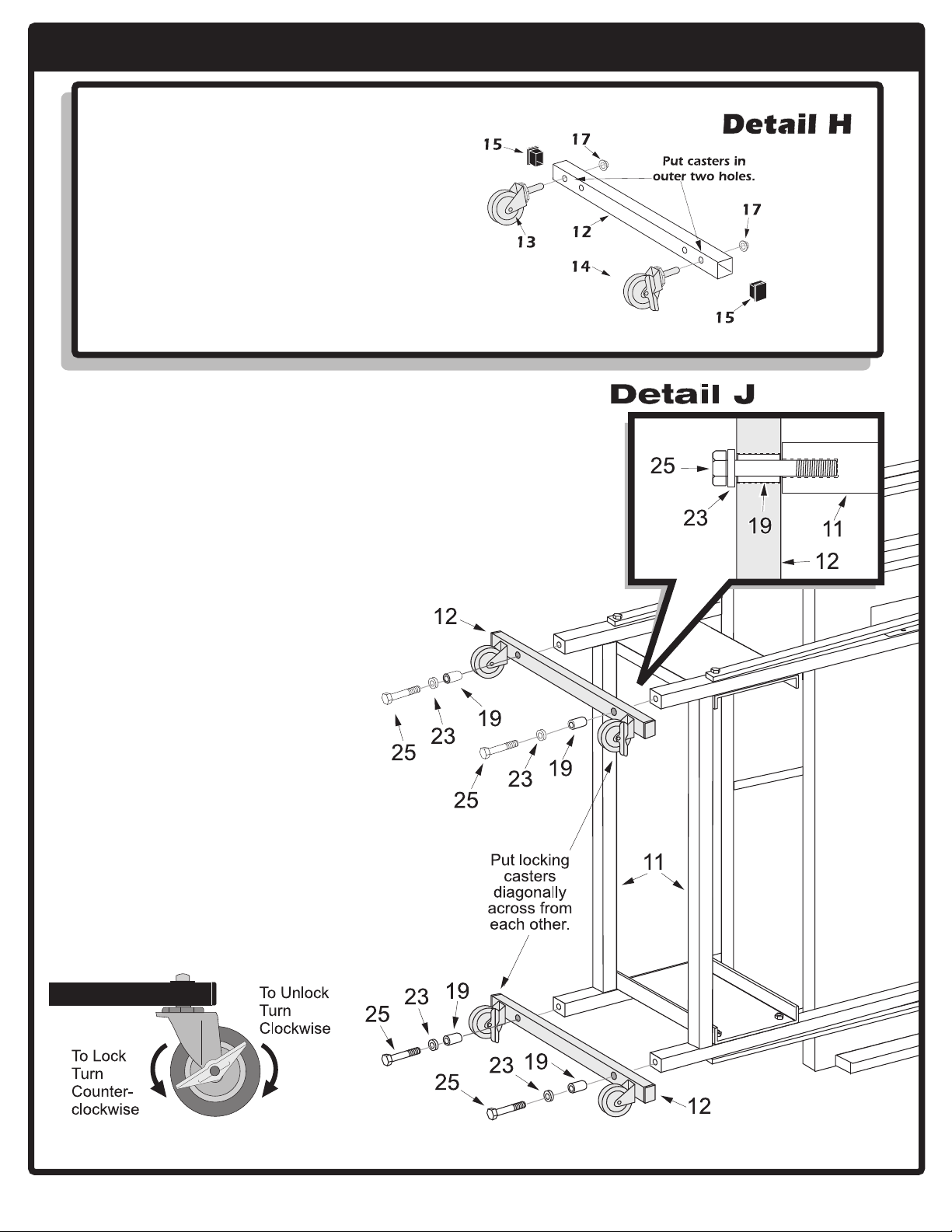
12.Put caps #15 into ends of caster
beams #12 (see Detail H).
13.Attach one non-locking caster #13
and one locking caster #14 to each
caster beam #12 with push nuts #17.
(See Detail H). Note: Use a hammer
to tap push nuts onto casters
securely.
5
14.Attach caster beams to upright
assemblies #11 with bolts #25,
washers #23, and spacer bushings
#19.
NOTE:Spacers bushings #19 slide
INSIDE caster beams #12 to keep
beams from crushing. (See Detail
J). Tighten bolts #25 tight.
15.Lock both locking casters #14. (See
Below).
NOTE: Casters should always
be locked unless moving table.
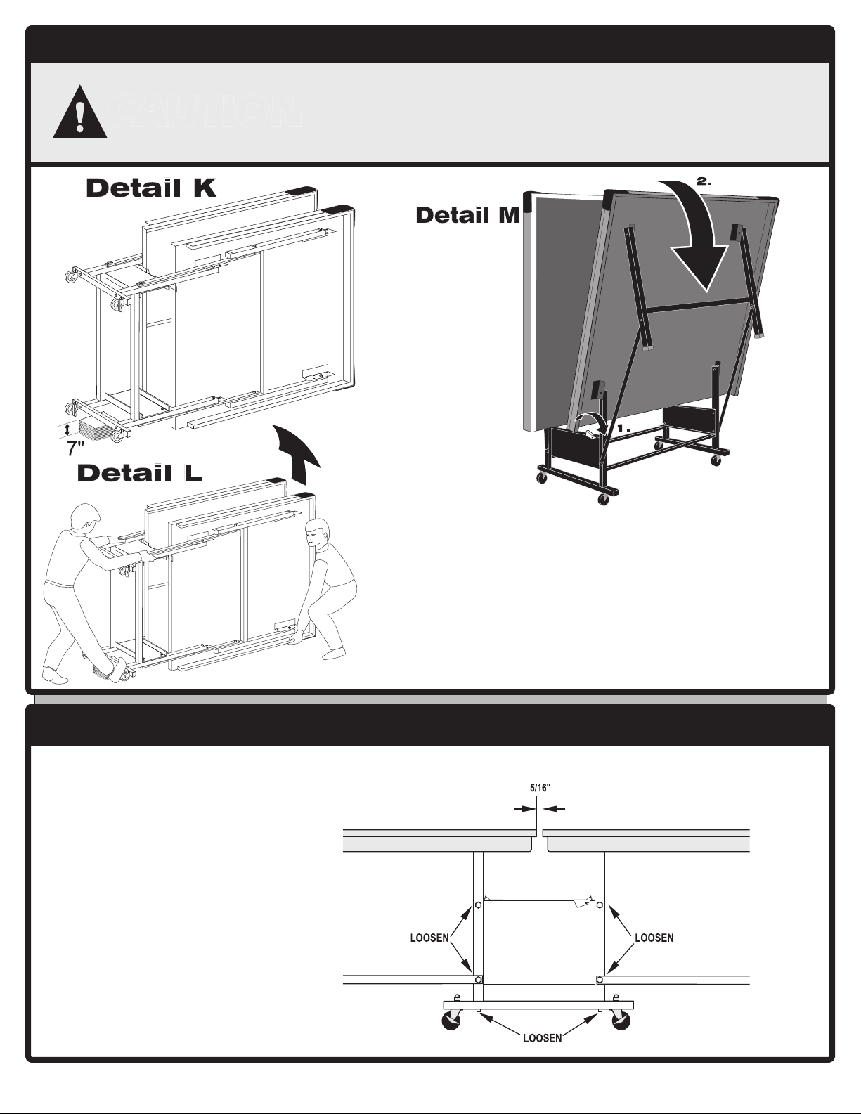
6. MAKING FINAL ADJUSTMENTS
5. SETTING TABLE UPRIGHT
16.Before lifting table, be sure both top halves are
locked in safety latches! Be sure casters are locked!
Put a 7 inch stack of magazines, wood, etc. under caster
beam nearest the floor to protect casters. (See Detail K).
17.With the help of one other adult, brace lower caster
beam with your foot and lift table upright. (See Detail L).
18.Once upright, release safety latch and lower table top
halves. (See Detail M and OPERATING INSTRUCTIONS
on next page).
At least two adults are needed to complete the following
steps. Be sure top halves are locked in safety latches! Be sure
that both locking casters are locked!
You must use a 7" stack of magazines (or similar block) to
protect the casters when lifting table upright!
CAUTION
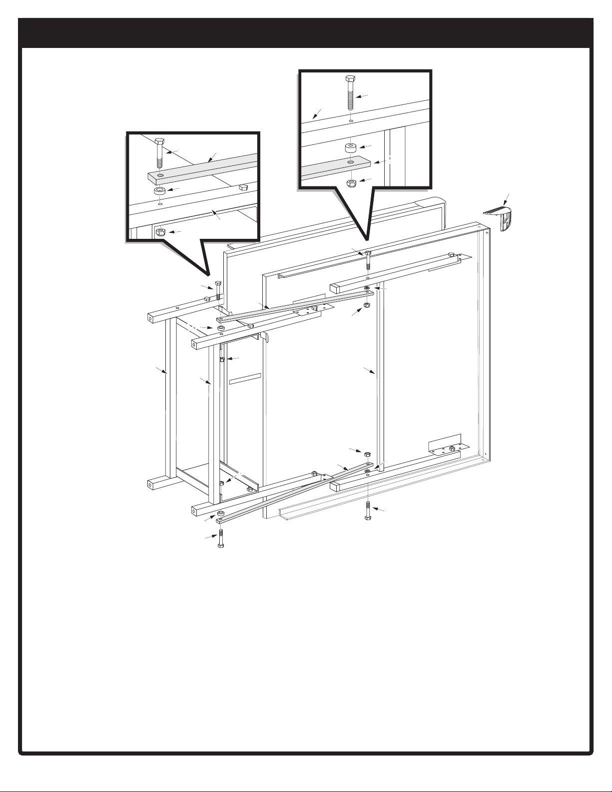
19.Loosen the six bolts shown
below and adjust table so
that the space between the
two table top halves
measures 5/16 of an inch.
20.Retighten these bolts.
21.Check over entire assembly
to be sure all nuts and bolts
are secure. Remember, do
not overtighten bolts at
joints that move.
6
If your gap between table halves is greater than 5/16" or uneven adjust it as follows.
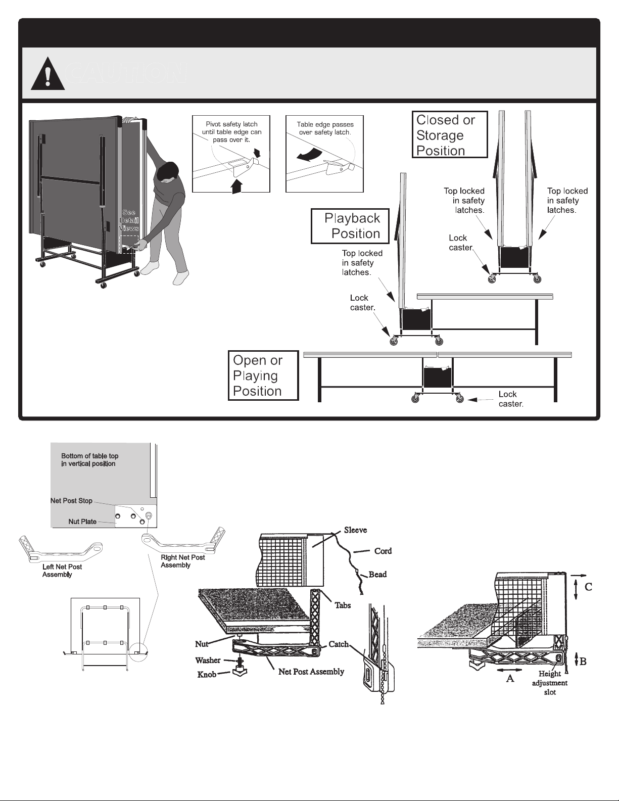
OPERATING INSTRUCTIONS
CAUTION
nn
nn
n ALWAYS LOCK TABLE TOP HALVES IN SAFETY LATCHES WHEN STORING,
MOVING, OR USING TABLE IN ITS PLAYBACK POSITION!
nn
nn
n
ALWAYS LOCK CASTERS, EXCEPT WHEN MOVING TABLE!
nn
nn
n
DO NOT SIT, STAND, WALK OR JUMP ON THIS TABLE!
To open table:
1. Lock both locking casters.
2. Release safety latch and pull table top
outward and downward. Be ready to support
weight of table top. Table top is heavy
3. Lower table top half.
To close table:
1. Lock both locking casters.
2. Lift table top half.
3. Check that top is locked in safety latches.
7
Net System Description 1. Net Post Assembly
Attach plastic net post as shown with washer and knob.
Note: there is a left and right net post assembly (See Net
System Description). Post assembly should rest flat
against nut plate. Slide the net sleeve over the vertical
post while the net post assembly is folded in toward the
side of the table top. Fold the net post assembly out
against the net post stop into the post and secure bead
chain in catch.
2. Adjustments
A - Adjust overall net tension by slightly loosening
the knob and moving net post assembly. Moder-
ately tighten knob. Net post assembly should be
kept square with the table by the net post stop (See
Net System Description).
B - Adjust tension of cord with bead chain on each
side. Assure that chain is fully seated in catch.
C - Position top of net to a regulation height of 6”
from the table surface by firmly gripping the verti-
cal net post within height adjustment slot.
3. Storage
Caution: To prevent damage to the net system and/or table top, the post assembly must be pivoted toward side of table before lifting table tops to storage position.
Loosen knob and pivot net post toward table side as far as it will go. Retighten Knob.
11
8
29
9
30
31
12
10
21
28
18
15
15
13
21
24
26
22
27
14
19
23
25
26
27
28
20
26
27
28
24
28
28
28
20
8
20
18
20
17
17
7
7
7
7
33
32
6
6
6
34
6
5
1
3
3
2
4
2L-7120-00
Copyright © 2007 ESCALADE, Inc.
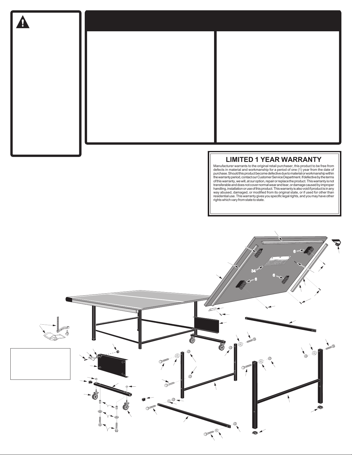
NOTE: Not all parts shown
below. At least one of every
part listed in the Product
Parts List is shown and
marked by its Item Number.
T8503 PARTS LIST
Use PART # column
when calling for
replacement parts.
QTY. column refers to
the total number of
pieces in product.
CAUTION
8
This table must be kept indoors
to prevent damage to the
playing surface. Dampness
and extreme temperature
changes which occur on
patios, or similar areas, can
cause wood to warp, swell,
crack or blister.
UNLEVEL FLOORS: If your
table does not seem level, it is
probably because the floor is
not level. Move table around
several inches to find the best
location for the table (first be
sure table is in playing position).
If floor is extremely unlevel,
the table may not play or
operate properly. If the table is
high in the center, shim up
under leg assemblies.
LIMITED 1 YEAR WARRANTY
Manufacturer warrants to the original retail purchaser, this product to be free from
defects in material and workmanship for a period of one (1) year from the date of
purchase. Should this product become defective due to material or workmanship within
thewarrantyperiod,contactourCustomerServiceDepartment.Ifdefectivebytheterms
of this warranty, we will, at our option, repair or replace the product. This warranty is not
transferable and does not cover normal wear and tear, or damage caused by improper
handling, installation or use of this product. This warranty is also void if product is in any
way abused, damaged, or modified from its original state, or if used for other than
residential use. This warranty gives you specific legal rights, and you may have other
rights which vary from state to state.
IMPORTANT NOTE ABOUT TOP: The top (playing surface) of your table is of a special
(particle board) construction. Like all wood products it can be affected by atmospheric
changes, meaning both temperatures and humidity. This may cause a slight sag, or
distortion as the top expands or contracts. This is normal and is no cause for concern
as it does not detract from the play or utility value of the table. To minimize this sag,
always store table in a dry area, in the folded up position.
Storage for your table:This table must be stored indoors to prevent damage to the
playing surface. Dampness and extreme temperature changes can cause the wood
to warp, swell, crack, or blister. When your table is not in use, it must be folded up in
a dry area.
Cleaning your table: To clean your table use a soft damp NOT WET cloth only. To
prevent damage to your table's playing surface DO NOT use any chemicals, abrasive,
or cleaning products on your table's playing surface.
Maintenance for your table: Be sure to oil all moving parts of your table, including pivot
points. This will insure the safety and ease of use of your table.
Care and Maintenance: You have purchased a
quality product that will give you years of
enjoyment. By following these simple steps you
will add to the life of your new table.
14A-6407-00 Table Top Half 2
22S-6715-05 Side Rail - Right Hand 2
32S-6716-05 Side Rail - Left Hand 2
42S-6714-00 End Rail 2
53M-6715-00 Corner Protector 4
62S-6139-01 Mounting Bracket 8
7701-105 #8 x 9/16 Screw 154
82S-6136-06 Name Panel 2
92S-6496-02 Safety Latch 2
10 1A-6943-01 Leg Assembly 2
11 1A-7009-01 Upright Assembly 2
12 8s-6503-01 Caster Beam 2
13 2Q-6459-00 Caster (Non-locking) 2
14 2Q-6460-00 Caster (Locking) 2
15 3M-6248-00 Tube Plug 4
16 2L-7120-00 Owner's Manual 1
17 601-84 3/8 Push Nut 4
18 904-62 Nylon Spacer 8
19 7B-6240-01 Spacer Bushing 4
20 704-104 Spacer 8
21 3M-6248-00 Leg Cap 4
22 701-160 ¼ -20 x 3-1/2 Hex Head Bolt 4
23 901-37 3/8 Heavy Washer 4
24 8S-6504-02 Linkage 4
25 1B-6047-00 5/16-18 x 3 Hex Head Bolt 4
26 701-82 ¼ -20 x 2 Hex Head Bolt 8
27 1B-6191-00 ¼ -20 x 2-3/4 Hex Head Bolt 8
28 701-26 ¼ -20 Locknut 20
29 801-120B #10 - 24 x 3/4 Phill Hd Screw 2
30 701-1 #10 Burr Washer 2
31 601-80B #10 - 24 Locknut 2
32 5A-6882-00 Net and Post Kit 1
33 1A-6285-00 Nut Plate 2
34 3M-6495-00 Paddel Pouch 1
ITEM # PART # DESCRIPTION QTY
ITEM # PART # DESCRIPTION QTY
Table of contents
Other TIGA Lawn Mower manuals


Popular Lawn Mower manuals by other brands


Nilfisk Egholm
Nilfisk Egholm City Ranger 2200 Operator's manual

Textron
Textron Jacobsen DH Series Safety and operation manual

Mountfield
Mountfield UV 34 E instruction manual

Remington
Remington K Series Operator's manual

LELY
LELY SPLENDIMO T Operator's manual

Craftsman
Craftsman EZ3 917.271053 owner's manual