Tigo TSS-200-US User manual

EI Automatic Transfer Switch (ATS)
2. Installation
1. General Information
3. Electrical connections
Conductor Schedule
Conductor Qty Type Size
Grid 4
Min. 90°C rated, insulated
(or bare-EGC conductors),
copper, solid or stranded
(not ne stranded)
L1, L2, N: 4-4/0 AWG,
EGC: 6-1/0 AWG
Load 4 L1, L2, N: 1/0-4/0 AWG,
EGC: 6-1/0 AWG
Inverter 4 L1, L2, N: 8-6 AWG,
EGC: 8 AWG
Communications 1 RS485 shielded, twisted
pair (2-wire) 24 AWG
Quick Start Guide - TSS-200-US
Pg 1 of 3
1. This document is for quick guidance only. For details, please refer to the Energy Intelligence (EI) ATS Installation & Operations Manual.
2. Damage caused by failure to follow the contents of the EI ATS Installation & Operations Manual is not covered by the warranty.
3. Before installing the system, check that the package contents are intact and complete against the packing list. If any damage is found or any component
is missing, contact your dealer.
1.4 EI ATS Enclosure Overview
1. Status display
2. 1¼" Inverter knockouts
3. 2½" Load knockout
4. 2½" Grid knockout
5. 1¼" Communication knockout
6. 1¼" unassigned knockout
7. 1¼" Generator knockout
8. Heat sink
9. 200A Main Circuit breaker Access door
!
!
ATTENTION – READ FIRST
!CAUTION – Use tools with insulated handles. Always wear appropriate PPE.
Although the Tigo ATS comes with
mounting hardware, use the appropriate
hardware for the mounting surface.
1.1 Package Contents
2.1 Mounting & opening the ATS
1.2 Required Tools
3.1 Electrical connections overview & conductor schedule
1.3 System wiring diagram
Item Quantity
TSS-200-US ATS 1
Mounting bracket 1
Quick Start Guide 1
M5 Security screws 2
M6 expansion screw with anchor 2
3pin wiring connector 1
6pin wiring connector 2
200A circuit breaker interlocking kit 1
Item Use
Wire cutter/crimp tool Wiring the ATS
Philips Screwdriver Wire terminals/Mounting
Rubber mallet/hammer Mounting
Drill Mounting
Level Mounting
2.5mm-8mm Allen keys Cover/Security Bracket/Wire Terminals
1. Reserve at least 12” on all sides of the ATS. Install
vertically or tilted back no more than 15 degrees.
2. Use a level and the mounting bracket to mark the
mounting holes.
3. Drill out mounting holes to 1.7” (45mm) depth.
4. Place the sleeve anchor in each hole, tap with the mallet/
hammer. Place mounting bracket aligned with the anchors
exposed through the screw holes and use the mounting
screws to attach to the wall.
5. Conrm bracket is level and screws are tight then lift ATS
on to the mounting bracket.
6. Insert security screws into each side of the bracket,
fastening the bracket to the ATS with a 4mm Allen key.
7. Remove the caps covering the Allen head screws on the
front cover. Using a 5mm Allen key, loosen the Allen
screws and remove the cover.
!CAUTION - Check that all Disconnect switches are OFF before wiring. Do not install any component of the EI System while
energized. Always wear appropriate PPE.
1 3
-
45 6
C
O
M
G
E
N
E
R
A
T
O
R
I
N
V
3
I
N
V
3
I
N
V
1
LOAD GRID
1
2
5 6 7
3 4
8
2 2
9
Inverter
communications
terminals
Manual Bypass
Jumper
200A Main Circuit Breaker
L1 L1L2 L2
Load terminals
Neutral terminals
Ground terminals
Inverter
terminals
Neutral
terminals
Note – 3 additional 2½” knockouts.
2 on the back. 1 on the right side.
PV Grid
NL2 L1 Utility
Meter
NG
Main Panel
Load
L2 L1
Grid
L2 L1N
G
Grid
G
Inverter
L1 L2 NG
PV1+ PV1-
…
PV4+ PV4- G N
200A
Breaker
Breaker
Battery
BAT+ BAT-
…
ATSEI Inverter
Refer to inverter manualfor
parallel dualbatteries
PV array
Generator
L1 L2 NG
Future
enhancement
Backup
+-
≥12”≥12”
≥12”
≥12”
≥12”
≤15°
PN: 002-00094-00 | REV 5.0 | Nov. 9, 2022

1. Run appropriately sized conduit from the inverter to ATS Inv knockout (2).
Use appropriate conduit ttings to ensure a water-tight seal. Route the
appropriate conductors from the inverter to the ATS.
2. Strip 10mm of insulation from the end of the Neutral and EGC of the
Inverter conductors. Insert into the Neutral and Ground busbars
respectively. Torque to 16.6ft-lbs (22.5 Nm).
3. Strip 10mm of insulation from the end of L1 and L2 of the Inverter
conductors. Insert into the Inverter’s breaker terminals. Torque to 1.5ft-lbs
(2 Nm).
!Do not wire until COMMUNICATIONS have been
completed.
3.5 Inverter power connections
EI Automatic Transfer Switch (ATS)
Quick Start Guide - TSS-200-US
Pg 2 of 3
3.2 Grid connections
3.3 Load connections
1. Run appropriately sized conduit to the Load knockout (3). Use
appropriate conduit ttings to ensure a water-tight seal and run the
Grid conductors.
2. Strip 10mm of insulation from the end of the Neutral and Ground
conductors and terminate at the neutral and ground bus bars with
16.6ft-lbs (22.5Nm).
3. Strip 10mm of insulation from the end of the L1 and L2 Load
conductors and terminate at the Load Terminals with 16.6ft-lbs
(22.5Nm).
Note – This connection feeds all power sources to the main load
panel.
!
Verify Grid disconnects/breakers, are in the OFF
position before wiring the ATS. !The COMMUNICATION cable must be connected before
the INVERTER power connections.
3.4 Inverter communications connections
1. Run appropriately sized conduit from the inverter to the Com knockout (5).
Use appropriate conduit ttings to ensure a water-tight seal. Route the 2-wire
RS485 cable and 2-wire 12VDC power cable from the inverter to the ATS.
2. Locate the top 6-pin connector. Connect one end of the RS485 wires to spring
terminals 3and 4at the ATS.
3. Locate the bottom 6-pin connector. Connect one end of the DC power wires
to spring terminals +12V and GND.
4. At the inverter, connect the other end of the DC power and RS485wires to the
2-pin and 3-pin connectors located above the PV input terminals. Ensure
inverter pin +and –are connected to pin +12V and GND at the ATS.
Ensure inverter pin Aand pin Bare connected to pin 3and pin 4at the ATS.
1. Run appropriately sized conduit to the Grid knockout (4). Use
appropriate conduit ttings to ensure a water-tight seal and run the
Grid conductors.
2. Strip 10mm of insulation from the end of the Neutral and Ground
conductors and terminate at the neutral and ground bus bars with
16.6ft-lbs (22.5Nm).
3. Strip 10mm of insulation from the end of the L1 and L2 Grid
conductors and terminate at the 200A Main Circuit with 16.6ft-lbs
(22.5Nm).
Note – This connection feeds power to the ATS from the utility
grid. Direct connection to utility feeders or a line side may
require coordination with the local utility company.
Note – CTs are factory installed to monitor grid power.
A
1
2
3
4
5
6
G B
CN8
PN: 002-00094-00 | REV 5.0 | Nov. 9, 2022
Tigo Energy, Inc.
655 Campbell Technology Pkwy
Campbell, CA 95008
T: +1 408 402 0802
https://support.tigoenergy.com/
8. Your Customer Service Contact
6. Commissioning
CAUTION – Electrical shock hazard. Always wear the appropriate PPE when energizing the EI Residential System components.
Prerequisites:
The EI Battery, EI Inverter, EI ATS, and Smart Meter are installed and electrically connected as per the installation manual.
Note: If you do not have access to the customer’s WiFi, then you must perform the manual bypass procedure in Section 3.6.
1. Turn on the EI Battery DC switch.
2. Turn on the EI Inverter DC Disconnect switch at the bottom of the inverter.
3. Verify that the Rapid Shutdown Initiator is in the depressed (out) position.
4. Turn on the inverter the white circuit breaker inside ATS.
5. Turn on the internal EI ATS 200A main circuit breaker and all OCP and disconnect switches on the grid side.
6. If the inverter does not on, please follow the battery force start procedure below to turn it on.
7. Open the EI App and begin the commissioning process.
Note: - The “battery” light on the ATS will turn solid green when the inverter detects the grid.
8. Contact Tigo Customer Care team to enable the ATS
9. Follow the manual bypass procedure in Section 3.6 to change the bypass switch from manual to auto bypass.
10. Using a multimeter, check the grid, battery, and PV voltage on the EI Inverter terminal blocks. All reading should be within spec.
11. Replace the EI ATS black safety cover, close the ATS door, and torque the Allen screws to 1.8ft-lbs (2.5Nm).
Note: If the inverter does not turn on after Step 7, then follow this force start procedure.
1. Open the cover to the right of the EI Battery power switch labeled Force Start.
2. Press and hold the push button until the “leaf” LED on the battery cabinet is ashing green to force start the inverter.
Once the forced start process completes, the EI Inverter error light will ash red since it will not detect grid voltage.
EI Automatic Transfer Switch (ATS)
Quick Start Guide - TSS-200-US
Pg 3 of 3
5. Pre-power checklist
Check Item Acceptance Criteria
ATS installation The ATS is installed correctly, securely and reliably as per the instructions.
Conduit/Cable layout Conduit/cables and conductors are properly routed and labeled IAW Code and local requirements.
Cable connections The AC output conductors, DC input conductors, and communications cables are labeled and connected correctly and securely.
Grounding Ground conductors are connected correctly, and securely.
Conduit connections All conduit attachments are sealed and bonded.
Disconnect switches All external disconnect switches are in the OFF position.
Workmanship The wirebox and installation area are left clean and accessible.
4. LED Status
Symbol Function Color Status Action Description
Grid Green
ON N/A Grid power is ON
OFF N/A No Grid power
Communications Green
ON N/A Normal operation
OFF 0.5s on / 0.5s off Abnormal communications with the
inverter
System Status Green
ON N/A Normal operation (on-grid)
Flashing 1s on/off N/A Normal operation (off-grid)
Fault Red
ON 0.5s on / 0.5s off A Fault has occurred
OFF N/A Normal operation
Flashing 1s on/off 1s on / 3s off The connected loads are overloading
the available output power
Issue Check
In grid-on operation the ATS does not
switch over when there is loss of grid.
1. Turn OFF the EI Inverter and the grid.
2. Open the ATS door and check the grid and INV conductors are properly connected to the correct terminals.
3. The ATS requires an activation. Refer to Section 3.6. Call Tigo Customer Care team: 408-402-0202
Load panel has no power.
1. Check the Status Display (1) for error codes and follow recommended steps if codes are active.
2. The ATS requires activation. Refer to Section 3.6. Call Tigo Customer Care team.
3. Verify ATS to EI Inverter communication cable is installed properly.
4. If issues persist, please contact Tigo Customer Care team.
7. Troubleshooting
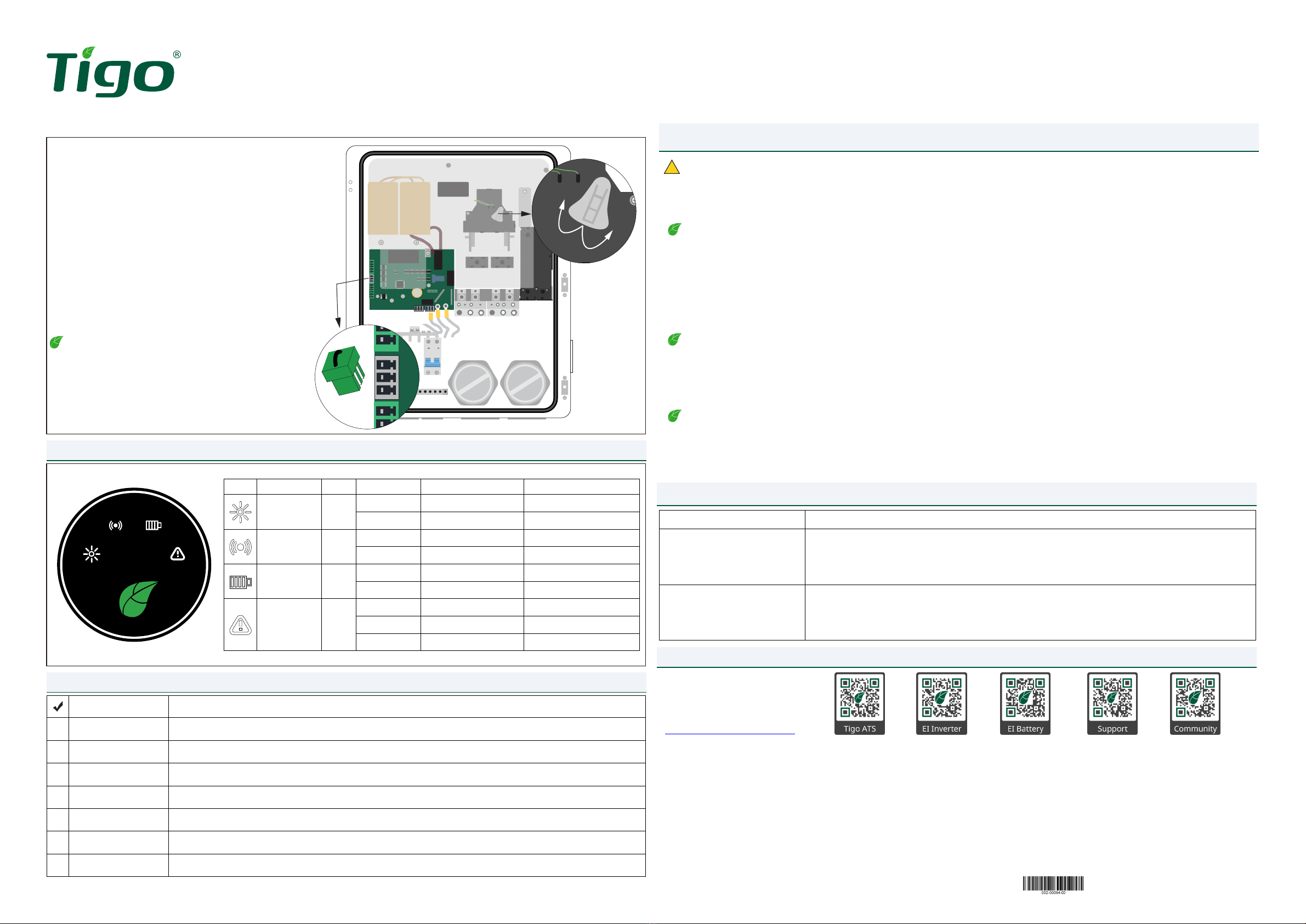
3.6 Manual Bypass Jumper Installation
The internal bypass switch is used to electrically bypass the EI ATS during
system maintenance. When switched to the ON position, grid power is
routed directly to the home electrical service panel. However, if
commissioning occurs at a later date, then the bypass feature must be
switched manually so that the home will receive grid power until the day
of nal system commissioning.
Follow these steps to manually switch the EI ATS Bypass Switch if the
previous conditions exist:
1. Turn off the internal EI ATS 200A breaker.
2. Turn off the EI Inverter DC disconnect switch.
3. Turn off the 2-pole breaker in ATS that feeds utility power to the EI
Inverter.
4. Locate the 3-pin connector in the accessories kit and jump pin 1 and
pin 3 using a small wire.
5. Plug the connector into the EI ATS terminal labeled RSD+ and RSD-.
6. Remove the EI ATS black safety cover and turn the bypass switch to
the on position.
Note – To change from manual to auto bypass, unplug the 3 pin
connector, remove the jumper wire, and plug the 3-pin
connector back into the RSD terminal. This ensures the
connector will be available for future maintenance or
troubleshooting.
RSD+ RSD-
OFF
ON
!
PN: 002-00094-00 | REV 5.0 | Nov. 9, 2022
Other Tigo Switch manuals


Popular Switch manuals by other brands


 quick start guide")

Icron
Icron Icron WiRanger user guide

Manufacture Corporation
Manufacture Corporation 94-1518PF user guide

Master View
Master View CS-114A user manual

TP-Link
TP-Link TL-SF1016D Mounting guide

Micas
Micas M2-S6510-32C Hardware installation and reference guide

HP
HP PROCURVE 2610-PWR Series Management and configuration guide