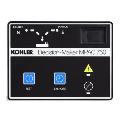
Kohler M340+ Building instructions

AutomaticTransferSwitches
Models:
M340+
Logic:
Microprocessor
TP-5672 11/95d
Service and Parts
U.S.A.Plant ISORegistered

Table of Contents
SUBJECTPAGE SUBJECTPAGE
SafetyPrecautions and InstructionsI...........
Introduction i.................................
ListofRelated Manualsi........................
Service Assistance i...........................
Section 1.Specifications 1-1...................
Purpose ofSwitch 1-1...........................
ComponentsofSwitch 1-1.......................
Ratings1-2....................................
InterpretingaTransferSwitchPartNumber1-3.....
Specifications1-4...............................
StandardFeatures1-4.......................
Shunt-Jumper-Controlled Accessories1-5......
OptionalFeatures1-5........................
Section 2. Operation 2-1.......................
LEDIndicators2-1..............................
ControlSwitchesand Indicators2-2...............
Sequence ofOperation 2-3.......................
NormalSourceFailure 2-3....................
NormalSourceRestoration 2-4...............
Sequence ofOperation Programmed Transition 2-6.
NormalSourceFailure 2-6....................
NormalSourceRestoration 2-7...............
ToDisconnectThe P1Plug 2-9...................
ElectricalOperation Test2-9.....................
Section 3.Troubleshooting Guide 3-1..........
Section 4.ControllerTroubleshooting 4-1......
Powertothe System4-2.........................
Keypad And StatusPanel4-3....................
NormalSourceVoltage and Frequency 4-6.........
Emergency SourceVoltage and Frequency 4-9.....
System-Status,Not-In-AutomaticError4-11........
System-Status,System-Alert4-12................
ContactorPosition FaultErrorMessages4-12......
TransferHang ErrorMessage 4-12................
Power-DownErrorMessage 4-12.................
RAMOrMemoryErrorMessage 4-13.............
ManualTransferMessage 4-13...................
Manual-to-Off TransferMessage 4-13.............
Fault#1 OrFault#2 Message 4-14................
Programming Mode Not-In-Off 4-15...............
Engine OperatesWhen itShouldNot4-16.........
Engine Will NotStart4-18........................
Area Protection 4-20............................
ShuntJumper-Controlled Options4-21.............
InphaseMonitor4-23............................
SourceMonitors4-24............................
PlantExerciser4-27.............................
TimeDelays 4-32...............................
ManualOverride 4-33...........................
Off Delays 4-34.................................
Section 5.AccessoryTroubleshooting 5-1......
OptionalAccessories5-2........................
Emergency SourceThree-PhasePhaseOption 5-2.
TestSwitches5-4...............................
TimeDelayOverride Option 5-10.................
Preferred SourceSwitch 5-14....................
RelayAuxiliaryDryContacts5-15.................
MainShaft AuxiliaryDryContacts5-22............
Meters5-23....................................
BatteryCharger5-47............................
ManualOperation Switches5-54..................
Load Shedding Contacts5-63....................
RemoteCommunication—RS/232 OrRS/485 5-65. .
Section 6.Service Parts 6-1....................
Introduction 6-1.................................
InnerPanel6-2.................................
Accessories6-5................................
TimeDelay6-5.................................
Sourcemonitors6-5.............................
TestSwitches6-5...............................
TimeDelayOverride Switches6-5................
Preferred-SourceSwitches6-5...................
AuxiliaryContacts—Relay6-5....................
AuxiliaryContacts—MainShaft 6-5................
Meters6-6.....................................
PlantExercisers6-11............................
BatteryChargers6-11...........................
SourceMonitors—Normaland Emergency 6-12....
Load-Shed Contacts6-12........................
TimeDelays 6-12...............................
AppendixA. GlossaryofAbbreviationsA-1.....
AppendixB. GeneralControllerInformation B-1.
AppendixC.CommonlyUsedAccessories C-1. .
SafetyPrecautionsand InstructionsI
TP-5672 11/95
Safety Precautions and Instructions
Atransferswitch,like anyotherelectromechanical
device,can pose potentialdangerstolife and limbif
improperlymaintained orimprudentlyoperated.The
bestwayto preventaccidentsisto be aware of the
potentialdangersand to always use good common
sense.Belowaresome generalprecautionsrelating to
theoperationofatransferswitch.Thismanualcontains
severaltypesofsafetyprecautionswhich are explained
below.SAVE THESE INSTRUCTIONS.
DANGER
Dangerindicatesthe presence ofa hazardthatwill
causeseverepersonal injury,death,orsubstantial
propertydamage if the dangerisignored.
WARNING
Warning indicatesthe presence ofa hazardthatcan
causeseverepersonal injury,death,orsubstantial
propertydamage if the warning isignored.
CAUTION
Caution indicatesthe presence ofa hazardthatwill or
can causeminorpersonal injuryorpropertydamage if
the caution isignored.
NOTE
Notecommunicatesinstallation,operation,or
maintenanceinformation thatisimportantbutnot
hazardrelated.
Safetydecalsare affixed tothe generatorsetin
prominentplacesto advisethe operatororservice
technician ofpotentialhazards.The decalsare
reproduced heretoimprove operator recognition.Fora
furtherexplanation ofdecal information,refertothe
safetyprecautionsthroughout thismanual.Before
operating orservicing the generatorset, be sureyou
understand the messagesof these decals.Replace
decalsifmissing ordamaged.
Safetydecalsare affixed tothe transferswitchin
prominentplacesto advisethe operatororservice
technician ofpotentialhazards.The decalsare
reproduced heretoimprove operator recognition.Fora
furtherexplanation ofdecal information,refertothe
safetyprecautionsthroughout thismanual.Before
operating orservicing the transferswitch,be sureyou
understand the messagesof these decals.Replace
decalsifmissing ordamaged.

II SafetyPrecautionsand InstructionsTP-5672 11/95
AccidentalStarting
Accidentalstarting.
Cancause severeinjuryordeath.
Disconnectbattery cablesbeforeworking on
generatorset(negativelead firstand reconnectit
last).
WARNING
Accidentalstarting cancause severeinjuryor
death.Turn generatorsetmasterswitchtoOFF
position,disconnectpowerto battery charger,and
remove battery cables(remove negativelead firstand
reconnectitlast)todisablegeneratorsetbeforeworking
on anyequipmentconnected to generatorset. The
generatorsetcan be started byautomatictransfer
switch or remotestart/stop switch unless these
precautionsarefollowed.

SafetyPrecautionsand InstructionsIII
TP-5672 11/95
Battery
Sulfuric acidin batteries.
Cancause severeinjuryordeath.
Use protective gogglesand clothes.Batteryacidcan
cause permanentdamage to eyes,burnskin,and eat
holesinclothing.
WARNING
WARNING
Explosion.
Cancause severeinjuryordeath.Relays in
battery chargercause arcs orsparks.
Locatein a well-ventilated area.Keep explosive
fumesaway.
Sulfuric acidin batteries cancause severeinjuryor
death.Sulfuricacidin battery can cause permanent
damage to eyes,burnskin,and eatholesinclothing.
Alwayswearsplash-proofsafetygoggleswhenworking
around the battery. If batteryelectrolyteis splashed in
the eyesoron skin,immediatelyflushthe affected area
for15minuteswithlargequantitiesofclean water.Seek
immediatemedicalaidinthecaseofeyecontact. Never
addacidtoabatteryoncethebatteryhasbeenplacedin
service.Thismayresultin hazardous spattering of
electrolyte.
Sulfuric acidin batteries cancause severeinjuryor
death.Sulfuricacidin battery can cause permanent
damage to eyes,burnskin,and eatholesinclothing.
Alwayswearsplash-proofsafetygoggleswhenworking
around the battery. If batteryelectrolyteis splashed in
the eyesoron skin,immediatelyflushthe affected area
withlarge quantitiesofclean water.Continue flushing
withwateruntil emergency help arrivesSeek
immediatemedicalaidinthecaseofeyecontact. Never
addacidtoabatteryoncethebatteryhasbeenplacedin
service.Thismayresultin hazardous spattering of
electrolyte.
Explosioncancause severeinjuryordeath.Battery
gases can cause an explosion.Do notsmoke orpermit
flame orsparkto occurneara batteryatanytime,
particularlywhen itisbeing charged.Avoidcontacting
terminalswithtools,etc., to preventburnsand sparks
thatcouldcause an explosion.Removewristwatch,
rings,and anyotherjewelrybefore handling battery.
Neverconnectnegative(--) battery cableto positive(+)
connection terminalofstartersolenoid.Do not test
batteryconditionbyshorting terminalstogether.Sparks
couldignite batterygasesorfuelvapors.Ventilate any
compartmentcontaining batteriesto prevent
accumulation ofexplosive gases.To avoidsparks,do
notdisturb battery chargerconnectionswhile batteryis
being changed.Always turn battery chargeroff before
disconnecting battery connections.Remove negative
lead firstand reconnectitlastwhen disconnecting
battery.

IV SafetyPrecautionsand InstructionsTP-5672 11/95
HazardousVoltage/
ElectricalShock
DANGER
Hazardous voltage.
Will cause severeinjuryordeath.
Do notopen enclosure until all powersourcesare
disconnected.
(600 Voltand above)
DANGER
Hazardous voltage.
Will cause severeinjuryordeath.
Disconnectpowersourcesbeforeservicing.
Barriermustbe installed afteradjustments,
maintenance,orservicing.
(600 Voltand above)
WARNING
Hazardous voltage.
Cancause severeinjuryordeath.
Disconnectpowersourcesbeforeservicing.
Barriermustbe installed afteradjustments,
maintenance,orservicing.
(under600 Volt)
WARNING
Hazardous voltage.
Cancause severeinjuryordeath.
Do notopen enclosure until all powersourcesare
disconnected.
(under600 Volt)
Hazardous voltage cancause severeinjuryor
death.Wheneverelectricityispresent, thereisthe
hazardofelectrocution.Openmaincircuitbreakeronall
powersourcesbeforeservicing equipment. Electrically
ground the generatorsetand electricalcircuitswhen in
use.Nevercomeintocontactwith electrical leadsor
applianceswhen standing inwateroron wetground,as
the chance ofelectrocution isincreased undersuch
conditions.
Hazardous voltage cancause severeinjuryor
death.Shortcircuits can cause bodilyinjuryand/or
equipmentdamage.Do notcontactelectrical
connectionswithtoolsorjewelrywhile adjustmentsare
made.Removewristwatch,rings,and jewelrythatcan
causeshortcircuits.
Hazardous voltage cancause severeinjuryor
death.To prevent the possibilityofelectricalshock,
disconnectharness plug beforeinstalling any
accessoriesinvolving connection totransformer
assemblyprimaryterminals76,77,78,and 79.
Terminalsare atline voltage!
(S340,R340,and R33 modelsonly.)
Hazardous voltage cancause severeinjuryor
death.To prevent the possibilityofelectricalshock,
disconnectharness plug beforeinstalling any
accessoriesinvolving connection totransformer
assemblyprimaryterminalson microprocessorlogic
models.Terminalsare atline voltage!

SafetyPrecautionsand InstructionsV
TP-5672 11/95
Hazardous voltage cancause severeinjuryor
death.To prevent the possibilityofelectricalshock,
de-energizethe normalpowersourceto be connected
tothe transferswitch beforemaking anyline orauxiliary
connections.
Hazardous voltage cancause severeinjuryor
death.De-energizebothnormalandemergencypower
sourcesbeforeproceeding.Movegeneratorsetmaster
switchoncontrollertoOFF position and disconnect
batterynegative(--) beforeworking on transferswitch!
Turnthe transferswitchselectorswitchtothe OFF
position.
Hazardous voltage cancause severeinjuryor
death.Disconnectinnerpanelharness atin-line
connector.Thiswill de-energizecircuitboard and logic
circuitry,butallowtransferswitchtocontinue tosupply
utilitypowerto necessarylighting and equipment.
Hazardousvoltagewillexistifanyaccessoriesmounted
toinnerpanelareNOTwired through the innerpanel
harness and de-energized byin-line connector
separation.Such accessoriesare atline voltage.

SafetyPrecautionsand InstructionsVII
TP-5672 11/95
Notes NOTE
HardwareDamage!Transferswitchmayuse both
American standard and metrichardware.Usethe
correctsizetoolsto preventrounding ofboltheadsand
nuts.
NOTE
Whenreplacing hardware,do notsubstitutewith
inferiorgradehardware.Screwsand nutsare
availablein differenthardness ratings.American
Standard hardware usesaseriesofmarkingsand
metrichardware usesa numeric systemtoindicate
hardness.Check markingson bolthead and nutsfor
identification.
NOTE
Amanualoperatorhandleisprovided on the transfer
switchformaintenance purposesonly.Returnthe
transferswitchtothe normalposition.Removemanual
operatorhandle(ifused)and storeiton the transfer
switchinthe place provided when serviceis completed.
NOTE
Performvoltage checks inthe ordergiven to avoid
damaging the switch.
NOTE
These battery chargersare designed strictlyforusein
thistransferswitchandconformwithULand CSA listing
requirementswherespecified.Do notuse battery
chargerbeforereading instructions.
NOTE
Connectsource and load phasesasindicated bythe
markingsand drawings. Improperconnectionsmay
causeshortcircuitsandcancausephase-sensitiveload
devicestorun inreverse orpreventload devicesfrom
functioning.
NOTE
ChargerDamage!Connectbattery chargeronlyto a
batterywiththesameDCvoltage asthe batterycharger
outputrating.
NOTE
Covertransferswitchduringinstallationtokeepdirt,grit,
metaldrill chips,etc., outofcomponents.Cover
solenoidmechanismduring installation.After
installation,usemanualoperating handleto position
contactorto ensurethatitoperatesfreely.Do notuse a
screwdrivertoforcecontactormechanism.

TP-5672 11/95 Introduction i
Introduction
Thismanualcoversthe operation, troubleshooting,
repair,and service partsforthe M340+microprocessor
logic controller.
Read through thismanualand carefullyfollowall
proceduresand safetyprecautionsto ensure proper
transferswitchoperationandtoavoidbodilyinjury.Keep
thismanualwiththe transferswitchforfuturereference.
Servicerequirementsareminimalbutarevery
important tothe safe and reliable operation of the
transferswitch; therefore,inspectassociated parts
often. It isrecommended thatan authorized service
distributorperformrequiredservicing tokeep theswitch
intop condition.
All information found inthispublication isbased on data
availableattimeofprinting.Themanufacturerreserves
the right tomakechangestothisliterature and the
productsrepresented atanytimewithoutnotice and
withoutincurring obligation.
List ofRelatedManuals
The logic controllercovered inthismanual ispartofa
familyofrelated devices.Separateservice and parts
manualsare availableforeach group withinthe overall
family.Besurethismanual isthe correctmanualforthe
automatictransferswitch.
Apowerconversion unitisincluded in each automatic
transferswitch.There arethree typesofpower
conversion unitsand eachtypeis coveredin a separate
service and partsmanual.Available powerconversion
unitsand the related manualnumbersare asfollows:
PowerSwitchDevice Service/
PartsManual
Mechanicallyheld or
electricallyheldcontactorsTP-5667
Molded-casecircuitbreakers
orswitchTP-5666
Standardcontactor,
programmed transition,and
Bypass-Isolation TP-5668
Service Assistance
Forsalesand serviceinthe U.S.A.and Canada check
the yellowpagesof the telephone directoryunderthe
headingGENERATORS—ELECTRICforanauthorized
service distributor/dealerorcall 1-800-544-2444.
KOHLER CO., Kohler,Wisconsin 53044 U.S.A.
Phone:920-565-3381
Fax:920-459-1646 (U.S.A.Sales)
920-459-1614 (International)
To ensuresupplyofcorrectpartsorinformation,make
note of the following identification numbersinthe
spacesprovided:
PARTNUMBER AND SERIALNUMBER
Partand serialnumbersare provided on the nameplate
attached tothe transferswitch.
PartNo.
SerialNo.

TP-5672 11/95 Specifications1-1
Section 1. Specifications
Purpose ofSwitch
An automatictransferswitch(ATS)isa device used for
transferring criticalelectrical loadsfroma normal
(preferred)source ofelectricalpowerto an emergency
(standby)source.Thistransferoccursautomatically
when the normalsourcevoltage fails,oris substantially
reduced,and the emergency source’s voltage has
reached an acceptablelevel.
Upon normalsourcefailure, the automatictransfer
switchcontrollersignalsthegeneratorset(s)tostartand
transfertothe emergency source.The automatic
transferswitchcontrollercontinuously sensesforan
acceptable normalsource and will retransferthe load to
the normalsource afterithasbeen restored to an
acceptablelevel.After retransferof the load, the
generatorsetstartsignal isremoved and the generator
set(s)isallowed toshutdown.
Components ofSwitch
Atypicalautomatictransferswitchincludesthe actual
powerswitching device and the logic controllerto
performpowermonitoring and transfersequencing
tasks.See Figure 1-1.Aninterface boardisalso
included tomatchthe controllerinputs/outputstothe
levelsrequired byaspecific switching device.
The three functionalunitsthatmakeupthe automatic
transferswitch aremounted in an enclosurewith a
hinged frontdoor.The controllermountson the back of
thefrontdoorsoitscontrolsandindicatorsareavailable
to an operator.Asignalcablewithin-line connectorsto
facilitatecomponentreplacementand door removal
connectsthe controllertothe interface board and the
switching devices.
12
3567111
1.PowerConversion Unit
2. InterfacePanel
3.LogicController
Figure 1-1.TransferSwitchComponents

1-2SpecificationsTP-5672 11/95
Interface
Power
Switching
Device
To Load
AutomaticTransferSwitch
Logic
Controller
Normal
(Utility)
PowerEmergency (Generator) PowerGenerator
Start
Generator
567112
Figure 1-2.BasicTransferSwitchBlock Diagram
Ratings
Anameplateisattachedtotheautomatictransferswitch
enclosure.See Figure 1-3.The nameplatelabel
includesafactorypartnumbercoded to provide
characteristicand rating information thataffects
installationandoperation.Copythepartnumberintothe
blank spacesprovided inthe introduction and then use
the chartsinFigure 1-4tointerpret the partnumber.
NOTE
Alsocopythe partnumberand serialnumberfromthe
nameplateintothe spacesprovided inthe Service
Assistance Section of the Introduction forusewhen
requesting service orparts.
KOHLER
AUTOMATICTRANSFERSWITCH
PARTNO.ZCS-160341-0800
SERIALNO.
VOLTS
PHASE
HERTZ
KOHLER CO.KOHLER WISCONSIN53044
AMPS
WIRES
POLES
295232
Figure 1-3.TransferSwitchNameplate

TP-5672 11/95 Specifications1-3
Interpreting aTransferSwitchPartNumber
Recordthetransferswitch partnumberintheboxes below.Thetransferswitch partnumberdefines
characteristics and ratings as explainedinthe accompanying chart.
Type ofSwitchType ofLogicVoltage &Frequency Numberof
PolesNumberof
WiresType of
EnclosureAmperage Rating Code
KohlerPartNumberKey
This chartexplainsthe Kohlertransferswitch partnumbering code system.The
sample partnumbershownisforastandardmolded-caseswitchwithM340+logic
rated at480 volts,60 hertz,3-phase,3-pole,and 4 wiresinaNEMA1 enclosurewith
an amperage rating of80 amperes.
SAMPLE PARTNUMBER
Classification ofPowerSwitch
M:Switch orCircuitBreaker
T:Electrically&MechanicallyHeld
Z:ContactorStyle
TypeofPowerSwitch
C:Contactor
E:ElectricallyHeldContactor
L:MechanicallyHeldContactor
M:Molded-CaseCircuitBreaker
N:Molded-CaseSwitch(no protection)
TypeofSwitch
S:Standard
B:Bypass
TypeofLogic
5:M340+
6:M340+with programmed transition
VoltageCode
60:600 Volt, 60 Hz66:480 Volt, 60 Hz
62:120 Volt, 60 Hz68:208 Volt, 60 Hz
63:220 Volt, 50 Hz71:380 Volt, 50/60 Hz
64:240 Volt, 60 Hz
NumberofPoles
2:2 pole,1 phase(MM_,MN_,TE_,TL_,devices
will be supplied with 3 poles)
3:3 pole,3 phase
6:4 pole, fullyrated switched poles
(no overlapping neutral)
NumberofWires
2:2wire
3:3wire
4:4wire
Enclosure
1:NEMAtype 1
Amperes
Availablesizes varywiththe type ofswitch.
MNS-566341-0080
Figure 1-4.TransferSwitchModelDescription

1-4SpecificationsTP-5672 11/95
Specifications
The specificationslisted belowareforthe M340+logic
controller.See the respective powerswitching device
manualforits specifications.
Standard Features
DNormalsourcevoltage sensing adjustablefrom
75%to130%ofnormalforpickup and from70%to
135%fordropout; providesmonitoring line-to-line
forall phasesof3-phaseswitches.
DTDNE(TimeDelayNormal-to-Emergency)
adjustable0to5minutes.
DTDES (TimeDelayEngine Start)adjustablefrom
0to6seconds.
DTDEN(TimeDelayEmergency-to-Normal)
adjustable0to30minutes.
DProgramTransition (Centeroff)—time delay
during transferwith neithersourceconnected to
the load.Adjustable0to2minutes.
DLCD digitalvoltmeter.
DLCD digitalrunning timemeter.
DLCD digitaltransfercounter.
DLCD digitalfrequency meter.
DStatuspanelwithkeypad data entry.
DArea protection with override.
DTDEC(TimeDelayEngine Cooldown)adjustable
from0to30minutes.
DGeneratorengine startcontacts.
DIndicatorsforswitch position—normaland
emergency.
DIndicatorsforsource available—normaland
emergency.
DLamptestswitch,momentary.
DUnderfrequency sensing—one phase emergency
source only.

TP-5672 11/95 Specifications1-5
Shunt-Jumper-ControlledAccessories
Enable ordisableshunt-jumper-controlled accessories
byaltering socketJP1onthe mainlogicboard.See
Figure 1-5.All shunt-jumperfeaturesare disabled from
thefactoryunlessthefunctionwasorderedatthetimeof
purchase.But features can be enabled afterfactory
deliverybyadding jumperstothe JP1socket.
OVRIDE
DELAY
EXER
FREQ
SEQUENCER
MONITORIN-PHASE
PHASE
VOLT/
PLANT
TIME
MANUAL
Main LogicBoard
JP1
567215
OFF DELAYS
Figure 1-5.LogicBoardAccessoryProgramming
Shunts
DManualOverride.Enabling manualoverride
allowsautomatictransferto an availablesource
when the connected sourcefails.Transfertime
delays will be bypassed.Disabling manual
override causesthe logicboardtowait formanual
operation.The logicboardwill notautomatically
seekthe availablesource.
DInphase Monitor.Abnormal inrushcurrentsfrom
switching between twolive powersources can
damage motorsand related equipment. The
purpose of the inphasemonitoristominimize
abnormal inrushcurrentsto equipmentwhen the
ATStransfersfromone sourceto a newpower
source.The inphasemonitorsamplesasingle
phase ofone source and comparesit to a single
phase of the othersource.When the twovoltages
arewithinthe desired phase angle and
approachingazero phase angle difference, the
inphasemonitorsignalsthe transferswitchto
operate.The transfermaybe fromutilityto
generator, fromgeneratorto generator,orutilityto
utility.
NOTE
Thisoption isavailable onlyon contactortype,
nonprogrammed transition switches. If the
contactorisnotof thistype, then the controllerwill
notallowthisoption to be enabled.Enablethis
accessorybyinstalling the INPHASE MONITOR
jumperon the controller’smainlogicboard.
DPhase Rotation and Anti-SinglePhasing.This
function provides sourcemonitoring forboththe
normaland emergency sources.The feature
includesphaserotation(ABConly)andanti-single
phase protection.Thisoption mustbe used in
conjunction with accessoryDD-05-Kin orderto
provide sourcemonitoring on the emergency side.
Enablethisaccessorybyinstalling the PHASE
SEQUENCERjumperon the controller’smain
logicboard.
DNormaland Emergency Source Sensing.This
function providesovervoltage sensing on all
phasesofthenormalsource,over/underfrequency
sensing on one phase of the normalsource,
overvoltage sensing on one phase of the
emergency source,and overfrequency sensing on
one phase of the emergency source.Enablethis
accessorybyinstalling the VOLT/FREQjumperon
the controller’smainlogicboard.
DPlantExerciser.Thisfunction enablesa no-load
plantexerciser.Userhasachoiceof7-day,14-day,
orcalendar-based exercisemodes.Enablethis
accessorybyinstalling the PLANTEXERjumper
on the controller’smainlogicboard.
DExtended TimeDelay.Thisfunction extendsthe
time delayto99minutesforTDNE,TDES,TDEN,
TDOE,TDON,and TDEC.Enablethisaccessory
byinstalling the TIMEDELAY jumperon the
controller’smainlogicboard.
DOff Position TimeDelay.Thisfunction enables
the time delayduring transferwhen neithersource
is connected tothe load.Enablethisaccessoryby
installing the OFF DELAYS jumperon the
controller’smainlogicboard.
OptionalAccessories
See AppendixCfordetailsofoptionalaccessories.The
nameplateincludesalistof the accessories selected.
See Figure 1-3.

Operation 2-1TP-5672 11/95
Section 2. Operation
ControlSwitches and Indicators
Variousoptionalcontrolswitchesand indicatorlamps
maybe presenton the transferswitch doordepending on the options chosen.See Figure 2-1forLED,Switch,
and Keylocations.
ContactorPosition TimeDelays
SourceAvailable
SystemStatus
AccessoryActive
·
PlantExerciserLoad Shed InphaseMonitorArea Protection
NormalOnEndEmergency Engine Start
NormalToEmergency
Emergency ToNormal
Engine Cooldown
Off Position
NormalEmergency
Not InAutomatic
Programming Mode NotinOff
Flashing,LocalSteady,Remote
·
· · ·
·
·
·
·
·
·
·
·
·
SystemAlert
· ·
Off
·
·
· · · ·
· ·
TESTSWITCH
NORMALTEST
MANUAL
TRANSFERTO
NORMAL
AUTO
TRANSFERMANUAL
TRANSFER
MANUAL
TRANSFERTO
EMERGENCY
BYPASS
EMERGENCYTO
NORMALTIMEDELAY
MANUAL
TRANSFERTO
OFF
BYPASS NORMAL
TOEMERGENCY
TIMEDELAY
AUTOINHIBIT
Figure 2-1.FrontPanel
LEDIndicators
ContactorPosition.LEDsindicatetransferswitch
position—NORMAL(green),EMERGENCY(red),or
OFF (yellow).
Source Available.LEDsindicatesourcewith
acceptablevoltage and frequency—Normal(green)
and/orEmergency (red).
SystemStatus
NotinAutomatic(red).LEDflashestoindicatethat
Testswitchisactuated,orAuto/Manualswitchisinthe
Manualposition.
SystemAlert(red).LEDflashestoindicate possible
problemwithcontactororlogicoperation.Systemalert
will alsoflashifanyfaultsignalsarereceived fromthe
generatorset.
Programming ModeNotinOff (yellow).LEDflashes
toindicatethatprogramming switchisinthe LOCAL
position.Asteady,nonflashing lightindicatesthat the
programming switchisinthe REMOTEposition.

2-2Operation TP-5672 11/95
TimeDelays
EngineStart(If emergency sourceisa generatorset).
ONLEDindicatesthatengine-start time delayistiming.
ENDLEDindicatesthattheenginehasbeensignaledto
start.
NormaltoEmergency.ONLEDindicatesthat the
normal-to-emergency time delayistiming.END LED
indicatesthat the time delayhas completed timing.
Emergency toNormal. ONLEDindicatesthat the
emergency to normaltime delayistiming.END LED
indicatesthat the time delayhas completed timing.
EngineCooldown.ONLEDindicatesthat the
generatorsetengine cooldowntimeristiming.END
LEDilluminatesuntil the engine has shutdown.
Off Position.ONLEDindicatesthat the time delayoff
positionistiming.ENDLEDindicatesthatthetimedelay
has completed timing.
AccessoryActive
PlantExerciser.PlantexcerciserLEDindicatesthat
the systemisinthe exercisermode.
LoadShed.LoadshedLEDindicatesthatprogrammed
load shedding isactive.
Inphase Monitor(available on ZCtype powerswitches
only). InphasemonitorLEDindicatesthat the sources
are being monitored forphaserelationshipto allow
inphasetransfer.The inphasemonitorwill permit
transferfromemergency to normaland normalto
emergency when sourcesare nearsynchronization.
NOTE
When a programmed transition switchisordered, the
inphasemonitoroption isdisabled bythe
microprocessor.
Area Protection.Area protection LEDindicatesthat
the controllerisinthe area protection mode.The
generatorwill be signaled toSTARTand the contactor
will transfertothe emergency position and remainthere
whilein area protection.
Programming ModeSwitch
NOTE
Theprogrammingmodeswitchkeysshould be keptina
safe placeto preventunwanted tampering withthe
transferswitchcontrol.Donotleavethe programming
switchinthe LOCAL position withthe transferswitch
unattended.
Remote.Allowsbothstatusmonitoring and setting of
the transferswitchcontrolsbyaconnected personal
computer.
Off.Transferswitchstatus settingsand powersource
maybe monitored fromthe localLCD displayor
connected computers.
Local. Allowsbothstatusmonitoring and setting of
transferswitchcontrolfromthe microprocessor’sLCD
displayand keypad.
ControlSwitches
TestSwitch(Standard).Movethe testswitchtothe
TESTposition tosimulate a normalsource outage.
Not-in-Automatic systemstatuslightwill flash.
Bypass N-ETimeDelay Pushbutton Switch
(Option).If the bypass normal-to-emergency time
delaypushbutton ispressed when
normal-to-emergency time delayison, time delaywill
end.
Bypass E-NTimeDelay Pushbutton Switch
(Option).If the bypass normal-to-emergency time
delaypushbutton ispressed,when
emergency-to-normaltime delayison, time delaywill
end.
ManualTransfertoEmergency Switch(Option).
When the transferswitchcontrol isinthe manualmode
ofoperation and manualto emergency isrequired,
press the manualtransfer-to-emergency pushbutton to
causethe transferswitchtotransfertothe emergency
position.
ManualTransfertoOff Switch(Option).When the
transferswitchcontrol isinthe manualmode of
operation and manualto off isrequired,press the
manualtransfer-to-emergency pushbutton tocausethe
transferswitchtotransfertothe off position.
ManualTransfertoNormalSwitch(Option).When
the transferswitchcontrol isinthe manualmode of
operation and manualto normal isrequired,press the
manualtransfer-to-emergency pushbutton tocausethe
transferswitchtotransfertothe normalposition.
Auto/InhibitSwitch(Option).If the auto/inhibitswitch
isinthe AUTOposition, the transferswitchwill operate
normally. If the switchisinthe Inhibitposition, the
transferswitchwill not transferunderany conditions.

Operation 2-3TP-5672 11/95
Sequence ofOperation
This section describesthe correctoperation ofa
microprocessor-controlled transferswitch.
Sequence ofOperation StandardSwitch
WhentheNormalSource Fails
1.The source-available normalLEDturnsoff.
2.The time-delay-engine-startONLEDilluminates
toindicatethe engine-start-time-delayistiming.
3.The time-delay-engine-startEND LEDilluminates
toindicatethe engine hasbeen signaled tostart.
4.The source-available emergency LED
illuminates.
5.The time-delaynormal-to-emergency ONLED
illuminatestoindicatethe normal-to-emergency
time delayistiming.
6.The time-delaynormal-to-emergency END LED
illuminatestoindicatethe time delayhas
completed timing.
7.The load-shed LEDilluminatesat the sametime
all loadstobeshed are disconnected fromthe
switch(ifequipped withload-shed option).
8.The inphasemonitorLEDilluminates(ifequipped
withinphasemonitoroption on ZCtype power
switchesonly).The controllermonitorsthe two
voltagestomakesuretheyare ata desiredphase
angle and approaching zero phase angle
difference.
9.Thecontactortransferstotheemergencyposition
afterthe load-shed time-before-transfertimerhas
completed timing.The contactor-position normal
LEDturnsoff and the contactor-position
emergency LEDilluminates.The inphasemonitor
LEDturnsoff.
10.Afterthe load-shed time-after-transfertimerhas
completed timing, the selected loadsforthe
emergencysourceare nowreturnedtotheswitch.
The load-shed LEDturnsoff (ifequipped with
load-shed option).

2-4Operation TP-5672 11/95
WhentheNormalSource Returns
1.The source-available,normalLEDilluminates.
2.The time-delayemergency-to-normalONLED
illuminatestoindicatethe emergency-to-normal
time delayistiming.
3.The time-delayemergency-to-normalEND LED
illuminatestoindicatethe time delayhas
completed timing.
4.The load-shed LEDilluminatesat the sametime
all loadstobeshed are disconnected fromthe
switch(ifequipped withload-shed option).
5.The inphasemonitorLEDilluminates(ifequipped
withload-shed option).
6.The contactortransferstothe normalposition
afterthe load-shed time-before-transfertimerhas
completed timing.The contactor-position
emergency LEDturnsoff and the
contactor-position normalLEDilluminates.
7.Afterthe load-shed time-after-transfertimerhas
completed timing, the selected loadsforthe
normalsource arereturned tothe switch.The
load-shed LEDturnsoff (ifequipped with
load-shed options).
8.The time-delayengine-cooldownONLED
illuminatestoindicatethe generatorsetengine
cooldowntimeristiming.
9.The time-delayengine-cooldownEND LEDstays
illuminated until the generatorhas shutdown.
10.The source-available,emergency LEDturnsoff.
Table of contents
Other Kohler Switch manuals

Kohler
Kohler ZCS-6 User manual

Kohler
Kohler MMS Instruction Manual

Kohler
Kohler KSS User manual

Kohler
Kohler ZCM-6 User manual

Kohler
Kohler KCS Instruction Manual

Kohler
Kohler 340 KN Series Instruction Manual

Kohler
Kohler G220 Guide

Kohler
Kohler GLS-1 User manual

Kohler
Kohler Decision-Maker MPAC 750 Instruction Manual

Kohler
Kohler KGS Specification sheet

Kohler
Kohler KSS Series User manual

Kohler
Kohler RXT Instruction Manual

Kohler
Kohler KEP User manual

Kohler
Kohler RSB Series Instruction Manual

Kohler
Kohler RDT User manual

Kohler
Kohler 1041995 User manual

Kohler
Kohler VERSO50 User manual

Kohler
Kohler KCT MPAC 1000 Instruction Manual

Kohler
Kohler KBS Instruction Manual

Kohler
Kohler KEP User manual