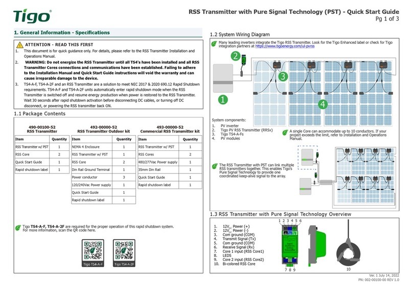
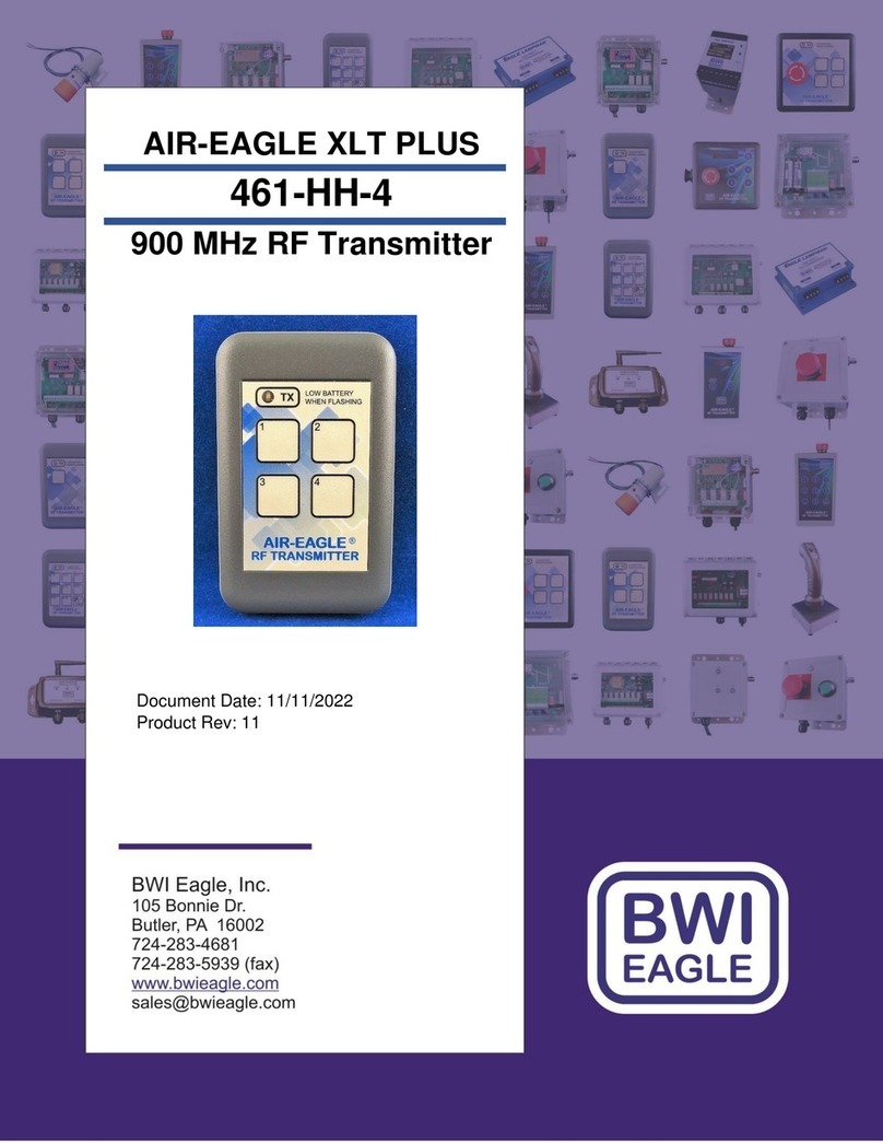
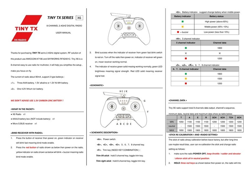
Tigo TS4-A-F User manual

©20231101 Tigo Energy, Inc.
*002-00157-00*
002-00157-00 Rev. 1.0
TS4-A-F/2F with
RSS Transmitters
Quick Start Guide
IMPORTANT SAFETY INFORMATION
LETHAL VOLTAGE MAY BE PRESENT IN ANY PV INSTALLATION
SAVE THESE INSTRUCTIONS
• AllPVRSEcomponentsmustbeinstalledandmaintainedbyqualiedpersonnelin
accordance with applicable electrical codes and instructions in the
TS4-A-F/2F with RSS Transmitters Installation Manual.
• Strictly adhere to all ANSI/NFPA 70 (North America) and local electrical codes.
• Improper installation may cause damage not covered by the warranty.
• Do not install TS4s that are physically damaged or have damaged or substandard wiring or connectors.
• Do not connect or disconnect TS4s under load.
• When used as a PVRSS solution, all solar modules in the array must be equipped with TS4-A-F/2F and RSS
transmitter PVRSE. Rapid shutdown is initiated upon AC power loss that stops power to the RSS transmitter.
TS4-A-2FTS4-A-F
RSS core
RSS transmitter
Install TS4-A-Fs
1. Connect the short input cables to the PV module.
2. Connect the long output leads to the adjacent TS4 to
create a string.
• Always assume that TS4s are in an ON state.
• Ensure cable glands face down and cannot
collect moisture.
• Disconnect TS4s from the array string before
disconnecting from a PV module.
•
Always connect short input cables
before connecting long output cables.
Failure to do so may void the warranty.
Install TS4-A-2Fs
If connecting a TS4-A-2F
to only one solar module,
connect the TS4 #2 input
cables to each other.
TS4 Mounting Options For frameless modules, use M8 bolts torqued to 10.2 Nm.
Frame
Frame thickness
Substrate
• Ifframethicknessis≤35mm(1.4in.),installwiththeTS4
label facing the PV module.
• NoportionoftheTS4maybe≤12.7mm(.5in.)fromthe
module substrate.
• Check PV module instructions for restrictions on mounting
devices under the module.
Output
cable
(long)
Output
cable
(long)
Removable
spring clips
M8 bolt holes
Input
cable
(short)
Input
cable
(short)

• All PVRSE components must be installed and
maintainedbyqualiedpersonnelinaccordancewith
applicable electrical codes and instructions in the
TS4-A-F/2F with RSS Transmitters Installation Manual.
• Improper installation may cause damage not covered
by the warranty.
• Adhere to ANSI/NFPA 70 (North America) and local
electrical code requirements.
The RSS Transmitter
Mount on a 35 mm DIN rail within a NEMA 1 (indoors)
or NEMA 4 (outdoors) enclosure.
• Transmitters must be on the same AC branch circuit as the inverter.
• Connect one standard, 100-240 V 12 V/1 A power supply per transmitter or connect one commercial, 180-
550 V/10 A power supply to up to ten transmitters with parallel connections.
Connect a Power Supply
100-240 V 12 V/1 A 180-550 V 12 V/10 A
TS4-A-F/2F with
RSS Transmitters
Quick Start Guide
Connect Signal Wiring
• Connect 14 – 22 AWG wires between
OUT/Tx
and
IN/Rx
terminals and between
OUT/COM
and
IN/COM
terminals.
• Check that Tx/Rx wires never contact
COM
terminals.
The maximum length of signal wire between
transmitters is 30.5 mm (100 ft.).
If connected correctly:
• The leader transmitter displays a
continuous red LED and a blinking
green LED.
• Follower transmitter LEDs blink green
simultaneously with no red.
Leader Follower Follower Last follower
Connect a Core
• Insert core wires into matching white/black core
terminals.
• Route up to ten negative PV conductors through a
core.
• The white side of the core must face the inverter.
• Maximum home run length is 300 m (985 ft.).
PV array White side Inverter
• All solar modules in an RSS string must be controlled
by a TS4-A-F or TS4-A-2F device. The rapid shutdown
system (RSS) controls all conductors.
• This RSS must be connected to an automatic system
that initiates rapid shutdown upon the activation of
the AC system disconnect. The RSS transmitter must
be powered from the same power that the rapid
shutdown initiator (RSI) will interrupt in order to
trigger a shutdown of the inverter.
• Rapid shutdown occurs within 30 sec. after an
AC disconnect (inverter or switch) disconnects AC
power to the inverter and RSS transmitter, ceasing
transmission of a keep-alive signal.
Model Max. Power Max. Input V Max. Input IMP Max. Input ISC Max. System V1
TS4-A-F 15 A 700 W 80 V 15 A 15 A 1000/1500 V
TS4-A-F 25 A 700 W 80 V 20 A 25 A 1000/1500 V
TS4-A-2F 15 A 1000 W 80 V 15 A 15 A 1000/1500 V
TS4-A-2F 25 A 1400 W 80 V 20 A 25 A 1000/1500 V
1Depending on connection method.
• Caution:Riskofreandshockhazard.Device(s)mustbeprotectedatsystemlevel(PVstring)withPVfuseratedmaximum20A,minimumvoltage
rating based on system voltage, 600 VDC, 1000 VDC, or 1500VDC.
• TS4-A-F/2F PV array (DC) conductors are 12 AWG.
• Normal operating temperature range is -30 °C to 70 °C.
• TS4-A-F/2Fs are compatible with the grid support function described in UL 1741 Tables SA9.1 and SA10.1: response to low- and high-voltage ride-
through (L/HVRT) and low- and high-frequency ride-through (L/HFRT) requirements.
• Connectorsfromdierentmanufacturerscannotbematedwitheachother.
• Modules must not be installed in readily accessible locations (Canada only).
WARNING – THIS PHOTOVOLTAIC RAPID SHUTDOWN EQUIPMENT (PVRSE) DOES NOT PERFORM ALL OF THE FUNCTIONS OF A COMPLETE
PHOTOVOLTAIC RAPID SHUTDOWN SYSTEM (PVRSS). THIS PVRSE MUST BE INSTALLED WITH OTHER EQUIPMENT TO FORM A COMPLETE PVRSS
THAT MEETS THE REQUIREMENTS OF NEC (NFPA 70) SECTION 690.12 FOR CONTROLLED CONDUCTORS OUTSIDE THE ARRAY. OTHER EQUIPMENT
INSTALLED IN OR ON THIS PV SYSTEM MAY ADVERSLY AFFECT THE OPERATION OF THE PVRSS. IT IS THE RESPONSIBILITY OF THE INSTALLER TO
ENSURE THAT THE COMPLETED PV SYSTEM MEETS THE RAPID SHUT DOWN FUNCTIONAL REQUIREMENTS. THIS EQUIPMENT MUST BE INSTALLED
ACCORDING TO THE MANUFACTURER’S INSTALLATION INSTRUCTIONS.
In accordance with Section 690.56(C)© of the NEC (NFPA 70), a rapid shutdown system label must be placed no more than 1 m (3 ft.) from the initiator
(AC disconnect) or service panel containing a means of disconnection if not at the same location.
Specications and Additional PVRSS UL 1741 Compliance Information
1 Core 1 terminals
2 Signal status LEDs
3 Core 2 terminals
4
IN Rx/COM
receive
terminals
5
OUT Rx/COM
receive
terminals
6 Power (– and +
12 V) terminals
1 2 3 4 5 6
Resources
Tigo Energy, Inc.
655 Campbell Technology Pkwy.
Campbell, CA 95008
+1 408 402 0802
Other manuals for TS4-A-F
2
This manual suits for next models
5
Other Tigo Transmitter manuals
Popular Transmitter manuals by other brands

Procare
Procare EF-6225 quick start guide
Converters.TV
Converters.TV CH-1107TX Operation manual
Hall Research Technologies
Hall Research Technologies UVA-WP manual
HK Instruments
HK Instruments DPT-Flow Series installation instructions

Broadata
Broadata LB-H2-E user manual
pyromation
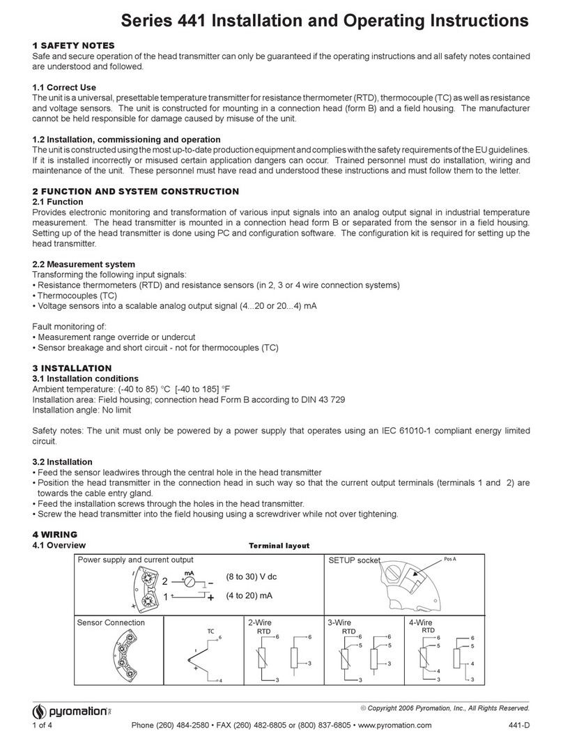
pyromation 441 Series Installation and operating instructions
