Tigo 490-00100-52 User manual
Ver. 1 July 14, 2022
PN: 002-00100-00 REV 1.0
RSS Transmitter with Pure Signal Technology (PST) - Quick Start Guide
Pg 1 of 3
1. General Information - Specications
!ATTENTION - READ THIS FIRST
1. This document is for quick guidance only. For details, please refer to the RSS Transmitter Installation and
Operations Manual.
2. WARNING: Do not energize the RSS Transmitter until all TS4's have been installed and all RSS
Transmitter Cores connections and communications have been established. Failing to adhere
to the Installation Manual and Quick Start Guide instructions will void the warranty and can
cause irreparable damage to the device.
3. TS4-A-F, TS4-A-2F and an RSS Transmitter are a solution to meet NEC 2017 & 2020 690.12 Rapid Shutdown
requirements. TS4-A-F and TS4-A-2F units automatically enter rapid shutdown mode when the RSS
Transmitter is switched off and resume energy production when power is restored to the RSS Transmitter.
Wait 30 seconds after rapid shutdown activation before disconnecting DC cables, or turning off DC
disconnect, or powering the RSS transmitter back ON.
1. 12VDC Power (+)
2. 12VDC Power (-)
3. Com ground (COM)
4. Transmit Signal (Tx)
5. Com ground (COM)
6. Receive Signal (Rx)
7. Core 1 input (RSS Core1)
8. LEDS
9. Core 2 input (RSS Core2)
10. Bi-colored RSS Core
1.1 Package Contents
1.3 RSS Transmitter with Pure Signal Technology Overview
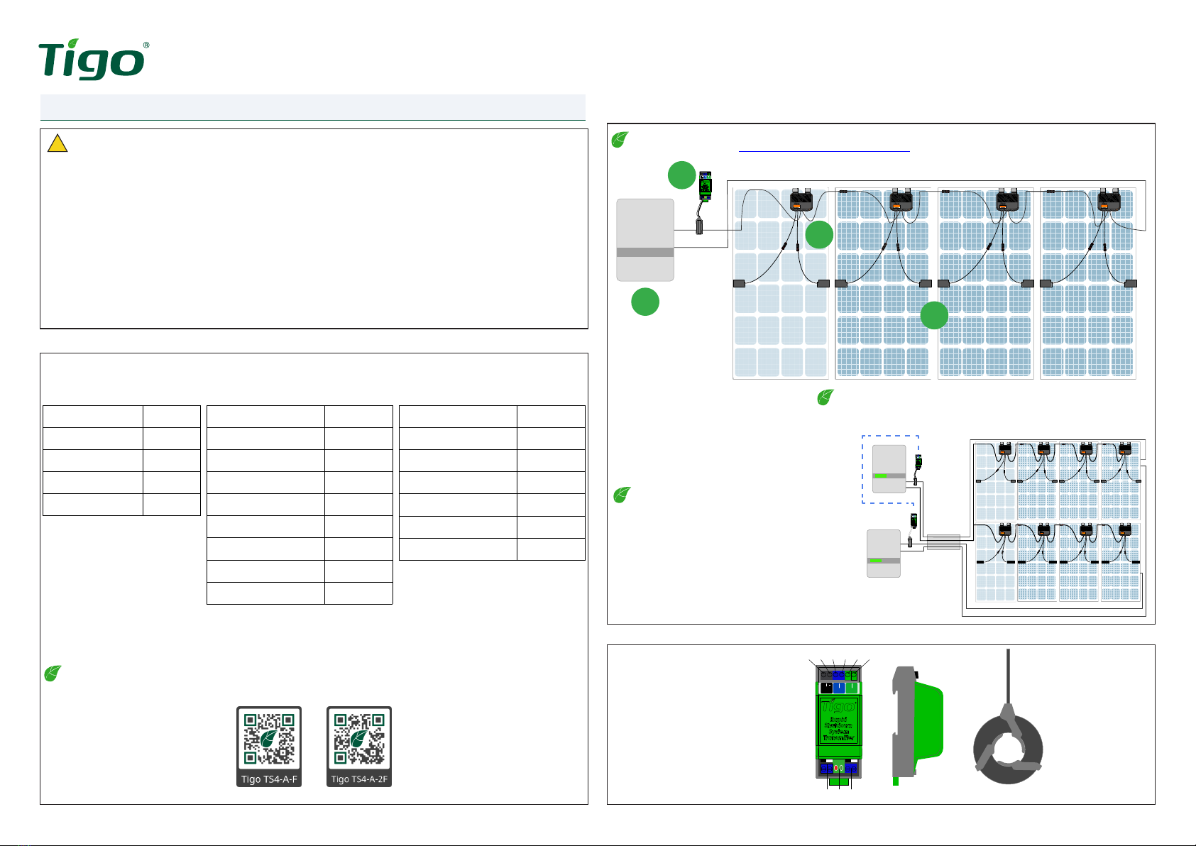
1.2 System Wiring Diagram
Item Quantity
RSS Transmitter w/ PST 1
RSS Core 2
Quick Start Guide 1
Rapid shutdown label 1
Item Quantity
RSS Transmitter w/ PST 1
RSS Cores 2
480/277Vac Power supply 1
35mm Din Rail 1
Quick Start Guide 1
Rapid shutdown label 1
Item Quantity
NEMA 4 Enclosure 1
RSS Transmitter w/ PST 1
RSS Core 2
Din Rail Ground Terminal 1
Power conductor 3
120/240Vac Power supply 1
Quick Start Guide 1
Rapid shutdown label 1
490-00100-52
RSS Transmitter
492-00000-52
RSS Transmitter Outdoor kit
493-00000-52
Commercial RSS Transmitter kit
Tigo TS4-A-F, TS4-A-2F are required for the proper operation of this rapid shutdown system.
For more information, scan the QR code here.
Many leading inverters integrate the Tigo RSS Transmitter. Look for the Tigo Enhanced label or check for Tigo
integration partners at https://www.tigoenergy.com/ul-pvrss
The RSS Transmitter with PST can link multiple
RSS transmitters together. This enables Tigo’s
Pure Signal Technology to provide one
coordinated keep-alive signal to the array.
A single Core can accommodate up to 10 conductors. If your
project exceeds the limit, refer to Installation and Operations
Manual.
System components:
1. PV inverter
2. Tigo PV RSS Transmitter (RRSx)
3. Tigo TS4-A-Fs
4. PV modules
+
12V
PWR
COM
Tx
OUT
COM
Rx
IN
TS4-A-F TS4-A-FTS4-A-F TS4-A-FTS4-A-FTS4-A-F TS4-A-FTS4-A-F
+
12V
PWR
COM
Tx
OUT
COM
Rx
IN
TS4-A-F TS4-A-F TS4-A-F TS4-A-F
TS4-A-F TS4-A-F TS4-A-F TS4-A-F
PWR
+
12V
PWR
COM
Tx
OUT
COM
Rx
IN
1
3
4
2
10
123456
789
+
12V
PWR
COM
Tx
OUT
COM
Rx
IN

Ver. 1 July 14, 2022
PN: 002-00100-00 REV 1.0
RSS Transmitter with Pure Signal Technology (PST) - Quick Start Guide
Pg 2 of 3
!POWER MUST BE DISCONNECTED THROUGHOUT THIS STEP.
2.2 Wiring multiple RSS Transmitters
2.3 Connecting the RSS Cores
If multiple RSS Transmitters exist in the system, the most effective way to mitigate crosstalk is to synchronize
the signal between the transmitters in a Leader-Follower method.
If only one transmitter is required, skip this step.
• Connect up to 10 RSS Transmitters
with PST.
• The total length of daisy-chain signal
wiring must not exceed 100ft (30m).
• Use 22-14 AWG twisted pair wire
(shielded recommended).
• Wire as shown
• Torque to 0.4Nm (3.5LB-in)
The RSS cores connect to the lower terminals of the RSS Transmitter.
1. Insert the wire with the white ferrule into the white terminal of
the Core 1 input (left side). Torque to 0.5 Nm max.
2. Insert the wire with the black ferrule into the black terminal.
Torque to 0.5 Nm max.
3. Repeat at Core 2 input (9) for two-core applications.
1. Using a red 22-14 AWG conductor, connect the 12V
output of the power supply to the + (1) and torque to
0.4Nm (3.5lb-in).
2. Using an 22-14 AWG black conductor, connect the 12Vdc-
of the power supply to the - terminal of the transmitter
(2) and torque to 0.4Nm (3.5lb-in).
3. Using an 22-14 AWG grounding conductor, connect the
AC and DC ground wires of the Power Supply to DIN rail.
!The RSS Transmitter MUST be on the same AC branch circuit as the inverter to meet NEC
690.12 Rapid Shutdown requirements.
You must complete Section 2.2 before powering on the RSS Transmitters.
2.4 Powering the RSS Transmitter
Each RSS Transmitter with PST requires 12VDC (+/-2%) and 1A from a DC power supply. The optional RSS
Transmitter Kits include a power supply. If sourcing a third party power supply, ensure the specication meet
the requirements found in the installation manual.
The RSS Cores are colored black and white to indicate signal directionality. The ends of the Core wires are
colored to match the RSSx and terminals.
At this time, the TS4-A-F/2F should be installed. No power is applied to the RSS Transmitter.
4. Route the PV array homeruns into the enclosure.
Pass only the negative homeruns through the RSS
Transmitter Core, with the black side of the Core
facing towards the PV array (polarity matters).
Continue the homeruns to the PV inverter. Each Core
can accommodate up to 10 homeruns. Use additional
Cores as necessary.
5. Pull conductors through the enclosure to the next
termination point (inverter).
1. Mount enclosure with appropriate mounting hardware for the surface.
2. Securely install the Ground terminal, power supply and RSS Transmitter with PST onto the 35mm Din Rail.
3. Route conduit to the enclosure. Use appropriate weather-tight ttings and bond conduit, as necessary.
Connect to ground terminal.
2.1 Installing the RSS Transmitter Kit
Prior to mounting, drill out all applicable conduit openings.
!Install the TS4-A-F and/or TS4-A-2F BEFORE powering on the RSS transmitter.
!The RSS Transmitter Kits include a DIN Rail power supply, RSS Transmitter with PST and a grounding
terminal. If not using a Tigo enclosure, conrm a 35mm DIN Rail can be installed and maintain the
environmental ratings of the equipment installed.
!Always use appropriate PPE.
!Always abide by prevailing codes/requirements to determine the number of PV
conductors that can t inside the 25.4mm (I.D.) core. Wire gauges and suppliers vary.
2. Installation
4
-12V
+
12V
PWR
COM
Tx
OUT
COM
Rx
IN
-12V
+
12V
PWR
COM
Tx
OUT
COM
Rx
IN
+
12V
PWR
COM
Tx
OUT
COM
Rx
IN
2 3
RSSx Leader RSSx Follower 1… ….RSSx Follower 10
-12V
-12V
-12V
+
12V
PWR
COM
Tx
OUT
COM
Rx
IN
+
12V
PWR
COM
Tx
OUT
COM
Rx
IN
+
12V
PWR
COM
Tx
OUT
COM
Rx
IN
Top view of RSS Tx with Pure Signal Technology
+
12V
PWR
COM
Tx
OUT
COM
Rx
IN +
12V
PWR
COM
Tx
OUT
COM
Rx
IN
Bottom view of RSS Tx
Class II double insulation
High Voltage
DANGER
E469960
Photovoltaic Rapid Shutdown System Equipment, QIJW
Ver. 1 July 14, 2022
PN: 002-00100-00 REV 1.0
RSS Transmitter with Pure Signal Technology (PST) - Quick Start Guide
Pg 3 of 3
7. Your Customer Service Contact
United States (HQ):
Tigo Energy, Inc.
655 Campbell Technology Pkwy
Campbell, CA 95008
EMEA Office:
Tigo Energy Italy
Srl Via Calamandrei 36 52025
Montevarchi Tuscany, Italy
Americas: +1 408 402 0802
International: 00800 2255 8446
https://support.tigoenergy.com/
LED Status Description Action
Red ON, Green Flashing Leader (transmitter 1) None; normal operation
Red OFF, Green ashing Follower (transmitters 2-10) None, normal operation
Red ON, Green OFF Error, not transmitting signal Remove power from all transmitters.
Verify all wiring is correct. Verify torque.
5. LED Status
Issue Check
Low string voltage
The TS4-A-F produces 0.6V per unit when the RSS Signal is not present. If the string Voc
is abnormally low (<100 volts), verify each RSSx has power and that the IN and OUT
connections are correct (if using multiple RSSx), and that the Cores are properly installed.
Lower voltage than expected One or more TS4s may not be connected properly. Use the RSS Signal Detector
(not included) to verify the TS4 is receiving the keep alive signal.
No output voltage at the string Verify all TS4s are connected to the modules and that all TS4s are connected to each
other.
6. Troubleshooting
!CAUTION – For personal safety always wear and use appropriate PPE.
3. Pre-Power Checklist
Check Item Acceptance Criteria
TS4 Installation All PV modules are connected to a TS4-A-F/TS4-A-2F.
Core directionality All Cores are facing the correct position (Black side towards the PV array).
Conductor signaling Only the negative conductors are run through the RSS cores and no more than 10
conductors per Core.
Distance The total round-trip distance of the PV conductors is <300m or <500m if Cores are
installed in series on the same strings for long distance applications.
Series transmitter wiring The transmitters are wired correctly and connections are secure.
Power supply Power supply is wired correctly, and connections are secure.
Conduit connections All conduit attachments are sealed and bonded, where necessary.
Workmanship Cable ties are secured evenly, have no sharp edges, the enclosure and installation
area are left clean and accessible.
Voltage check Check string voltage prior to powering up the system. Without the keep alive signal
the string voltage should equal 0.6V x # of PV modules in the string.
4. Commissioning
1. Follow the normal commissioning steps of the inverter(s) installed. Note - the RSS Transmitter must be
connected to the same AC branch circuit as the inverter to meet NEC 690.12 Rapid Shutdown requirements. By
connecting the inverter(s) to the grid, power is supplied to the RSS transmitter, turning it on.
2. The RSS Transmitter should now be powered and signaling the array to pass energy. Each string should now
have full voltage to the inverter.
!CAUTION – For personal safety always wear and use appropriate PPE.
This manual suits for next models
2
Other Tigo Transmitter manuals


Popular Transmitter manuals by other brands

AMG
AMG AMG4627B instruction manual

Wegener
Wegener DVT2000 instruction manual

Teledyne Analytical Instruments
Teledyne Analytical Instruments LXT-380 instructions

Firetide
Firetide HotPort 3203 Hardware installation guide

Rose electronics
Rose electronics UltraLink E Series Installation and operation manual

Lectrosonics
Lectrosonics SMB Series quick start guide


