Tilswall FY8233X User manual
Model: FY8233X
Digital Multimeter
User Manual

Manual Download
Q & A

Introduction
This digital multimeter is a small handheld digital instrument with
stable performance, high reliability and anti-drop performance. The
overall circuit design is centred on a large-scale integrated circuit
double-integral A/D converter and equipped with an overload
protection circuit, making it a compact instrument with superior
performance.
This meter can be used to measure DC/AC voltage, DC current,
resistance, diode, and continuity, non-contact AC voltage.
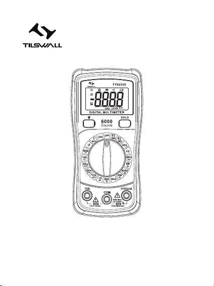
Panel Diagram
1. Non-contact voltage sensing area
2. LCD display
3. “ ” Backlight key
4. “HOLD” Data hold key
5. Function range switch
6. “10A” Input
7. “COM” Input
8. “ VΩmA ” Input
EN
-01-

-02-
Safety Information
This digital multimeter is designed according to IEC61010-1
600V(CATIII) and pollution degree 2.
To ensure that the meter can be used accurately and safely, please
read the instruction manual carefully.
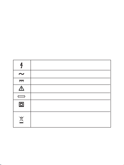
Safety Marks
High voltage warning
AC (alternating current)
DC (direct current)
Warning, important safety mark
Fuse
The instrument is protected by double insulation
or reinforced insulation.
This affixed product label states that this
electrical/electronic product must not be disposed
of in household waste.
-03-

Precautions for Use
• The meter can only be used with the provided test leads to meet
the requirements of safety standards. If the test leads are damaged
and needs to be replaced, you must replace with the test leads of
the same model or the same electrical specifications.
• Do not exceed the input limit specified for each range.
• Do not touch unused input terminals while the meter is measuring.
• When the range to be measured cannot be confirmed, set the
function range switch to the maximum range position.
• Before the function switch is switched, the test leads and the
circuit under test should be in open circuit state.
• Before measuring online resistance, please turn off all power in
the circuit and discharge all capacitors.
• When measuring voltages higher than DC60V and AC30V, be
careful and remember that your fingers can not exceed the
shielding part of test leads.
• When measuring TVs or switching power supplies, be aware that
there may be pulses in the circuit that can damage the meter.
-04-

Maintenance
• Before opening the back cover, the test leads should be
disconnected with the measuring circuit.
• In order to protect the internal circuit of the instrument, do not use
the meter until the resettable fuse is installed in this series of
instruments, the back cover is properly closed and the screws are
tightened.
• Use only a damp cloth and a small amount of detergent to clean
the meter, do not wipe the case with chemical solvents.
• If any abnormality is observed, immediately stop using the meter
and send it for repair.
Technical Specifications
Accuracy: ± (% of reading ± counts); Warranty period: 1 year
Environment temperature: 18°C to 28°C; Temperature humidity:
80%
General specifications:
Maximum voltage between any terminal and earth ground: CAT III
600V
Power: AAA batteries 1.5V x 2
Maximum display: 5999
Overrange indication: “OL”
Polarity display: negative polarity display “-”
Operating temperature: 0°C to 40°C
Storage temperature: -10°C to 50°C
Low voltage indication: display “ ”
Dimensions: 138x68x30 mm
Weight: about 170g (without batteries)
-05-
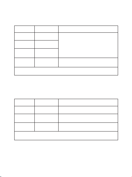
DC Voltage
Range Resolution Accuracy
± (0.5% of reading ± 2)
± (0.8% of reading ± 2)
Overload protection: PTC 600V DC/AC RMS
600mV
6V
60V
600V
0.1mV
0.001V
0.01V
0.1V
DC Current
Range Resolution Accuracy
± (1% of reading ± 2)
± (1.5% of reading ± 2)
± (3% of reading ± 2)
Overload protection: 10A: 10A fuse; mA: 600mA fuse
60mA
600mA
10A
10μA
100μA
10mA
-06-

AC Voltage
Range Resolution Accuracy
± (1.2% of reading ± 10)
Overload protection: 600V DC/AC RMS
Frequency range: 40Hz to 400Hz
Display: average value (RMS of sine wave)
600V 1V
Capacitance
Range Resolution Accuracy
± (4% of reading ± 10)
Overload protection: 600mA fuse
6000μF 100nF
AC Current
Range Resolution Accuracy
± (1.5% of reading ± 2)
± (3% of reading ± 2)
Overload protection: 10A: 10A fuse; mA: 600mA fuse
600mA
10A
100μA
100mA
-07-
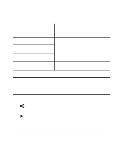
Resistance
Range Resolution Accuracy
± (0.8% of reading ± 2)
± (0.8% of reading ± 2)
± (1.0% of reading ± 2)
Overload protection: PTC 600V DC/AC RMS
600Ω
6kΩ
60kΩ
600kΩ
6MΩ
0.1Ω
1Ω
10Ω
100Ω
1kΩ
Diodes and Continuity Beeper
Range Description
Overload protection: PTC 600V DC/AC RMS
The on-resistance is less than 50Ω, the beeper
sounds.
Display approximate diode forward voltage
-08-

Live Wire Test
Turn the function knob to the Live position, and insert the red test
lead into the
VΩmA
, insert the red test lead into the power
socket, and the meter displays Live, which indicates that it’s the live
wire.
Usage
Precautions before operation:
1. Connect the power and check the 1.5V batteries first. If the
battery voltage is insufficient, “ ” will be displayed in the on the
screen, and the battery needs to be replaced. If “ ” is not displayed
on the screen, then follow the steps below.
2. The “ ” mark next to the test lead input jack indicates that the
input voltage or current should not exceed the indicated value,
which is to protect the internal circuit from damage.
3. Before measuring, the function range switch should be set to the
range you need.
DC Voltage Measurement
1. Insert the red test lead into the “
VΩmA
” jack, and the black
test lead into the “COM” jack.
2. Set the function range switch to the V and connect the test
leads to the power supply or load, the polarity of the red test lead
will be displayed on the screen at the same time.
-09-

Note:
DC Current Measurement
1. Insert the black test lead into the “COM” jack. When the
measured current does not exceed 600mA, insert the red test lead
into the “
VΩmA
” jack. If the measured current is between 600mA
and 10A, insert the red test lead into the 10A jack.
2. Set the function range switch to the V and connect the test
leads in series to the load to be measured, the polarity of the red
test lead connection will be displayed while the current value is
displayed.
1. When the voltage range to be measured cannot be confirmed in
advance, please set the function range switch to the maximum
range position, then reduce gradually until satisfactory resolution is
achieved.
2. If the display only shows “OL”, it means the range has exceeded
and the function range should be set to a higher range.
3. Do not input a voltage higher than 600V. It is possible to display
higher voltage, but it can trigger danger of damaging internal wiring
of instrument.
4. When measuring high voltage, pay special attention to avoid
electric shock.
-10-

Note:
1. When the current range to be measured cannot be confirmed in
advance, please set the function range switch to the maximum
range position, then reduce gradually until satisfactory resolution is
achieved.
2. If the display only shows “OL”, it means the range has exceeded
and the function range should be set to a higher range.
3. The “ ” mark next to the test lead input jack indicates that the
maximum input current (600mA or 10A) depends on the jack used,
excess current will burn out the fuse.
AC Voltage Measurement
1. Insert the red test lead into the “
VΩmA
” jack and the black test
lead into the “COM” jack.
2. Set the function range switch to V ~ and connect the test leads to
the power supply or load.
Note: See Notes 1, 2, 3, 4 for DC voltage measurement.
AC Current Measurement
Note: For the measuring method, see items 1, 2 for the DC current
measurement.
-11-

Note:
1. If the measured resistance exceeds the maximum value of the
selected range, the display will show “OL”. At this time, you should
select a higher range. When measuring resistance above 1MΩ, it
may take a few seconds for stable readings. This is normal for high
resistance measurements.
2. When there is no input, such as open circuit, the meter displays
“OL”.
3. When checking the online resistance, you must first turn off all
power in the circuit under test, and have all capacitors fully
discharged.
Resistance Measurement
1. Insert the black test lead into the “COM” jack and the red test
lead into the “
VΩmA
” jack.
2. Set the function range switch to the required Ω range position,
and connect the test leads to the measured resistance in parallel,
read the measurement results from the display.
-12-

Diode & Continuity Test
1. Insert the black test lead into the “COM” jack and the red test
lead into the “
VΩmA
”
jack. At this time, the polarity of red test lead is “+”.
2. Set the function range switch to position, connect the red
test lead to the anode of the diode under test and the black test lead
to the cathode of the diode, and read the approximate forward
voltage drop value of the tested diode on the display.
3. Connect the test leads in parallel to two points of the circuit under
test. If the resistance between these two points is lower than about
50Ω, the built-in beeper will sound to indicate that the two points are
conducting.
4. The instrument will recognize diode and continuity test automati-
cally without switching the function knob.
Capacitance Test
In order to avoid damage to the meter or the equipment under
test, before measuring the capacitance, you should cut off all the
power of circuit under test and have all high voltage capacitors fully
discharged. Use DC voltage range to make sure that the capacitors
have been discharged.
Do not measure any voltage higher than 250V DC/AC RMS to
prevent electric shock or damage to the meter.
-13-

Note:
1. Even if there is no indication, the voltage may still exist. Do not
rely on non-contact voltage detectors to determine whether there is
voltage on the wires, the detection operation may be affected by
the socket design, insulation thickness and different types, etc.
2. The interference sources of external environment (such as
flashlight, motor, etc.) may trigger non-contact voltage detection by
mistake.
1. Auto off: if the function key or range switch of meter is not in use
for about 20 minutes. The beeper will sound beep~beep to indicate
that the meter will enter sleep state soon before the meter is turned
off; before entering the sleep state, the beeper will sound beep
once then the meter enters the sleep state. Press any key or turn
the range switch to OFF to restart the meter to wake up the meter.
Non-contact AC Voltage
Measurement
Set the function range switch to the desired NCV range position,
the screen displays ---, place the top of the meter close to the
conductor. When the detected voltage is higher than 80V (RMS),
the beeper will make a Di~Di alarm sound, and the alarm sound will
change from slow to fast, the faster the closer to the conductor, the
screen displays “--L” at the same time to represent LOW (low
voltage), and “--H” to represent HI (high voltage).
Auto Off & Cancel Auto Off
-14-

2. Cancel auto off: before starting up, press the H button to turn the
meter on and release it after 2 seconds, the screen will automatical-
ly shut down and the symbol “ ” disappears, which indicates that
there is no automatic shutdown function. And this function can be
restored by starting up again after shutdown.
Please follow the steps below to replace the batteries:
1. Turn off the instrument power.
2. Unplug all test leads from the input jack.
3. Use a screwdriver to loosen the screws that fix the battery cover.
4. Remove the battery cover.
5. Take away old batteries or damaged fuses.
6. Replace with new 1.5V AAA batteries or new fuse.
7. Install the battery cover and tighten the screws.
Warning: To avoid electric shock, please check and confirm
that the test leads have been disconnected with the measuring
circuit before opening the back cover.
Before using the meter, please check that the back cover has been
tightened.
Battery Replacement
• User manual x1
• Test leads x 1 pair
• 1.5V AAA batteries x2
• Warranty card x1
• Cloth bag x1
Accessories
-15-


Made in China
Manufacturer: Huizhou FuYi Electronic Technology Co.,Ltd.
Work address: Dalou Iudustrial park, jinhu Road, Chenjiang
Town, Zhongkai High-tech District, Huizhou City,
Guangdong Province,China
EC REP
Prolinx GmbH
Brehmstr.56, 40239 Duesseldorf
Germany
Table of contents


