Unit UT151A User manual

P/N:110401102629

Item Page
I. Characteristics---------------------------------------------------------------------------------------- --------------3
II. Technical data------------------------------------------------------------------------------------------------------ 3
III. Operating method ------------------------------------------------------------------------------------------------9
IV. Maintenance of instrument ---------------------------------------------------------------------- ------------15
V. Accessories -------------------------------------------------------------------------------------------------------17
TABLE OF CONTENTS

3 1/2-bit DDM in the brand-new UT151 series is a kind of hand-held 3 1/2-bit digital
universal meter with stable performance and high reliability. The large-scale integrated circuits
and dual integral A/D transducer are the core design of circuits of the overall instrument and
overload protection with full range of functions is also provided. It can be used to measure the
DC voltage and AC voltage, electric current, resistance, capacitance, diode, triode, temperature,
frequency, battery and the circuit break-make. It's your ideal tool.
OVERVIEW
This instrument is designed and manufactured in strict accordance with safety requirements
of electronic measuring instrument in GB4793 as well as safety standards of IEC61010-1
and IEC100-2-O32. It also complies with the safety standards of double insulation, over
voltage CAT I 1000V, CAT II 600V and pollution class 2.Follow the instructions of this Manual,
or the protection of the instrument will be damaged.
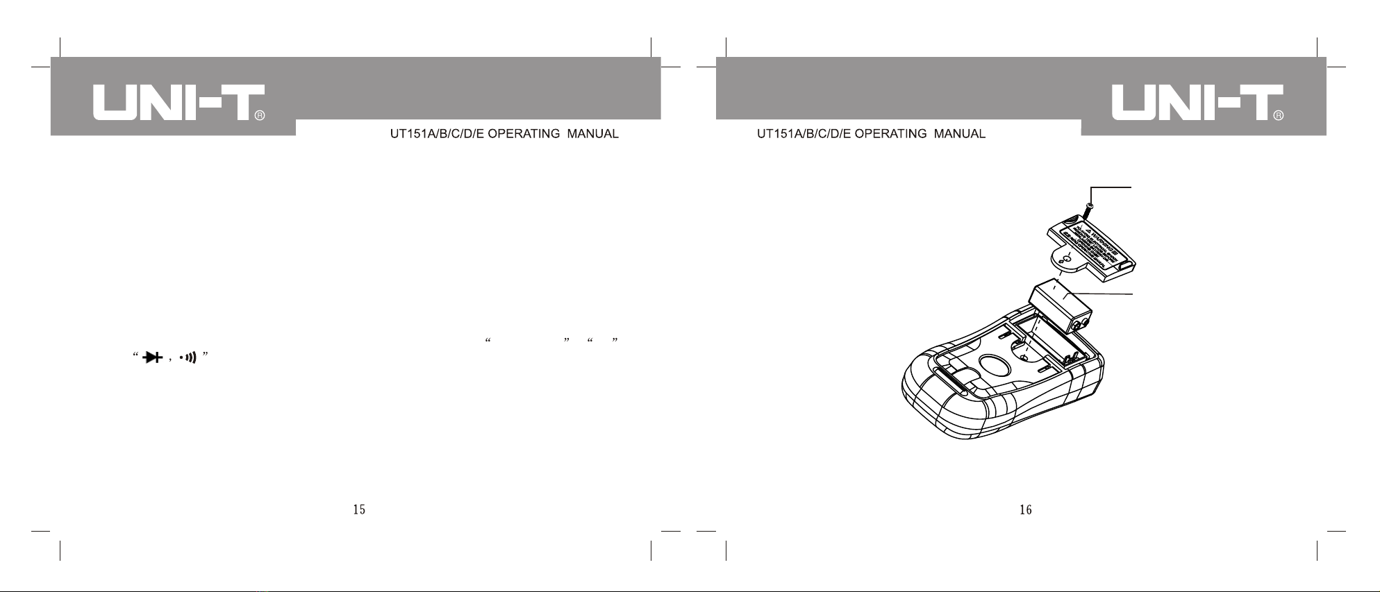
Ensure that it cannot be operated before the back cover is put in the place, otherwise there is
a risk of electric shock.
The range switch shall be installed at the correct position.
Check and ensure the insulation layer of the pen is in good condition without damage and
broken line.
The red and black pens should be inserted in the hole which meet the measurement
requirement; ensure well contact.
The input signal is not allowed to exceed the limit value to avoid electric shock and damage.
Changing range switch shift is strictly prohibited during the measurement of voltage and
current in order to avoid damaging the instrument.
SAFETY RULES AND PRECAUTIONS
If you want to change the bad fuse and you must use the one of the same type.
In order to avoid electric shock, the potential difference between common port COM and
the earth is not exceeded 1000V.
When the voltage to be measured is more than 60 DC or 30 Vrms AC, you must be careful
to avoid electric shock.
When the LCD shows the symbol of , you must change the battery in time to ensure the
measuring accuracy.
Turn off the power after finishing the measurement. If you do not use it for a long time, take
out the battery.
Don't operate this instrument under high temperature or high humidity. Especially, it cannot
be stored in damp environment. If the instrument is affected with damp, its performance will
be damaged.
Don't change the circuits of the instrument at random, otherwise, you will damage the
instrument and be in danger.
Maintenance: Clean the shell of the instrument with wet cloth or mild cleaning agent rather
than abrasive objects or solvent.
Symbols
Lower battery level
Buzzer
Fuse
Grounding
AC
Double insulation
Warning
DC
Diode

1. There are 30 ranges for function selection.
2. LCD display with visible zone 63 29mm
3. Over-range indication 1 .
4. The maximum value displayed of 1999(three and half digits)
5. Overload protection for the full range.
6. Automatic power cut-off
7. Temperature range Working temperature: 0 ~40 (32 ~104 ) Storage temperature:
-10 ~50 (14 ~122 )
8. Indication of lower battery level: The upper-left corner of LCD will show the symbol of
9. The function to keep number of all shifts.
10. Physical dimensions: 186mm x 91mm x 39mm
11. Weight: Approximate 300g (instrument +protection sleeve + bracket+ battery, excluding
pens)
I.CHARACTERISTICS
Accuracy: (a% reading +digit); the guarantee period is 1 year.
Ambient temperature: 23 5
Relative humidity: <75%
II.TECHNICAL DATA
2-1. DC voltage
nput impedance: 10MÙfor all ranges
Overloading protection: For 200mV range, 250V, DC or AC effective value. For other ranges,
750Vrms or 1000Vp-p peak value.
2-2. AC voltage
Range Resolution Accuracy
UT151A UT151B UT151C UT151D UT151E
(0.8%+3)
(1.5%+5)
1 mV
10mV
100mV
1 V
2 V
20 V
200 V
750 V
Input impendence: 10 MÙfor all ranges
Frequency range: 45Hz-400Hz
Overloading protection: 750 Vrms or 1000Vp-p peak
Display: Mean value (sine-wave effective value)
200 V
1000 V
100mV
1 V (0.8 %+2)
Range Resolution Accuracy
UT151A UT151B UT151C UT151D UT151E
2 V
20 V
1 mV
10mV (0.5%+1)
200mV 100µV

2-3 Direct current
Range Resolution Accuracy
UT151A UT151B UT151C UT151D UT151E
(0.8%+1)
(0.8%+1)
200 µA
2 mA
20 mA
200 mA
10 A
0.1µA
1µA
10µA
100µA
10 mA (2.0%+5)
(1.5%+1)
Overloading protection: uA, mA input: 200 mA /250V Ö5 × 20 mm
A input end: 10A/250V Ö6× 25mm
Maximum input current: 10A (For current over 5A, measuring time shall not exceed 15
seconds)
Measured voltage drop: 200mV for full range
2-4. Alternating current
Range Resolution Accuracy
UT151A UT151B UT151C UT151D UT151E
200 µA
2 mA
20 mA
200 mA
10 A
0.1µA
1µA
10µA
100µA
10 mA (3.0%+5)
(1.8%+3)
(1.0%+3)
(1.0%+3)
(1.0%+3)
Overloading protection: uA, mA input: 200 mA /250V Ö5 ×20 mm
A input end: 10A/250V Ö6× 25mm
Maximum input current: 10A (For current over 5A, measuring time shall not exceed 15
seconds)
Measured voltage drop: 200mV for full range
Display: Mean value (sine-wave effective value)
2-5. Resistance
Range Resolution Accuracy
UT151A UT151B UT151C UT151D UT151E
(1.2%+2)
(1.0%+2)
(1.2%+2)
200 Ù
2 kÙ
20 kÙ
200 kÙ
2 MÙ
20 MÙ
200 MÙ
0.1 Ù
1 Ù
10 Ù
100 Ù
1 kÙ
10 kÙ
100 kÙ[5.0% (reading-10)+10] [5.0% (reading-10)+10]
(1.5%+2)
Open circuit voltage: 700mV (for range of 200MÙ, the open circuit voltage is about 2.8V).
Overloading protection: 250V for all ranges, DC or AC effective value
Notice: At 200 MÙshift, the pen is short-circuited. It is normal for the display to show 10
digits. During measurement, these 10 digits shall be subtracted from the reading.
Relative humidity for measurement in 200MÙshift 65%
(0.8%+1)


2-11 Battery measurement (only for UT151A)
Range Resolution Accuracy Description
12 V
9 V
1.5 V
10 mV
10 mV
10 mV
(2.5%+2)
Built-in load resistance: 240Ù
Built-in load resistance: 1.8 KÙ
Built-in load resistance: 30Ù
Overloading protection: 500 mA/250V fuse
The damaged fuse must be replaced by the one of the same type.
III. OPERATING METHOD
Precautions before operation:
1) Press the POWER switch to check 9v battery. In case of lower battery voltage level,
will be shown on the display. In this case, you need to replace the battery.
2) symbol beside the pen hole means that input voltage or current shall not exceed the
indicated value so that the internal circuits can be protected from damage.
3) Prior to the testing, the functional switch shall be placed at the needed range.
4) Introduction of the instrument:
Power switch
LCD display
Data hold
Functional switch
Input socket
1
2
3
4
5
11
22
33
44
55

3-1 Measurement of DC voltage
1. Insert the black pen into the COM hole and the red pen into the V hole.
2. Place the functional switch at range scope; and connect the test pen to the power or load to
be tested. Polarity of the terminal connecting with the red pen will be shown at the same
time.
Notice
1) If the scope of voltage to be tested is not known, the functional switch shall be placed at the
maximum range which will be gradually lowered for testing.
2) If the display only shows 1 , it indicates over-range. In this case, the functional switch
shall be placed at higher range.
3) indicates that you must not input a voltage more than 1000 V. It is possible to show a
higher voltage, but it has a risk of damaging the internal circuits.
4) Special attention shall be given to measurement of high voltage to avoid electric shock.
3-2 Measurement of AC voltage
1. Insert the black pen into the COM hole and the red pen into the V hole.
2. Place the functional switch at V~ range scope; and connect the test pen to the power or load
to be tested.
Notice
1) Refer to Notice 1, 2 and 4 in the AC Voltage Measurement
2) indicates that you must not input a voltage more than 750 V. It is possible to show a
higher voltage, but it has a risk of damaging the internal circuits.
1. Insert the black pen into the COM hole. When the current for which the maximum value is
below 200 mA is measured, insert the red into mA hole. When the current for which the
maximum value is 10 A is measured, insert the red pen into 10 A hole.
2. Place the functional switch at range; and connect test pen to the circuit of load to be tested
in series. The polarity of red pen will be displayed together with the current.
3-3 Measurement of direct current
Notice
1) If the scope of current to be tested is not known, the functional switch shall be placed at the
maximum range which will be gradually lowered for testing.
2) If the display only shows 1 , it indicates over-range. In this case, the functional switch
shall be placed at higher range.
3) indicates that the maximum input current is 200Ma. The built-in fuse of 200mA/250V
Ö5 x 20 mm can effectively protect the circuit from burn-out. 10A range use fuse of 10A/250V
Ö6 x 25 mm for protection.
3-4 Measurement of alternating current
1. Insert the black pen into the COM hole. When the current for which the maximum value is
below 200 mA is measured, insert the red into mA hole. When the current for which the
maximum value is 10 A is measured, insert the red pen into A hole.
2. Place the functional switch at A~ range; and connect test pen to the circuit of load to be
tested in series.

Notice
1) Refer to Notice 1, 2 and 3 in the Direct Current Measurement.
1. Insert the black pen into COM hole and red pen into Ùhole.
2. Place the functional switch at Ùrange. Connect the test pen to the resistance to be test in
parallel.
Notice
1) If the resistance to be tested is more than the maximum value of the range selected, over-
range 1 will be shown. You shall select higher range. For resistance more than 1MÙand
above, the reading can become stable after several seconds; this is normal for high
resistance reading.
2) When input is not made, such as open-circuit conditions, the instrument shows 1 .
3) When you check the impendence of internal circuits, power supply to the circuit to be tested
must be cut off and capacitor charges must be totally discharged.
4) There are 10 digits at 200 MÙshort-circuit which shall be subtracted from the reading. For
example, 101.0 is shown in measurement of 100 MÙresistance and the 10 digits shall be
subtracted.
3-5 Resistance measurement
3-6 Capacitance testing
Prior to connection to the capacitance to be tested, note that time for zero reset is needed for
each change of range. Existing drift reading cannot influence the testing precision.
Notice
1) Although protection to the capacitance shift is set by the instrument, testing shall still be
carried out after capacitor discharge to avoid damage to the instrument or causing measuring
error.
2) In measuring capacitance, insert the capacitor into the capacitance testing seat.
3) In measuring large capacitance, it will take a certain time period to get stable reading.
4) Unit: 1pF=10 µF, 1nF=10 µF
-6 -3
3-7 Frequency measurement
1. Insert the red pen into the Hz hole and the black pen into COM hole.
2. Place the functional switch at kHz range; connect the test pen to the frequency source. You
can directly read the frequency from the display.
3-8 Temperature measurement
1. In measuring the temperature, insert the cold end (free end) of thermocouple sensor into the
temperature test seat and at the same time note the polarity. Place the working end
(temperature measuring end) on or inside the object to be tested. You read the temperature
directly from the display which is expressed in or .
3-9 Diode testing and buzzer continuity testing
1. Insert the black pen into COM hole and red pen into VÙhole (polarity of red pen + );
place the function switch at shift; connect the pen to the diode to be tested. The reading is
the approximate value of forward voltage of diode.
2. Connect the pen to both ends of circuit to be tested. If the resistance between both ends is
lower than about 10 Ù, the built-in buzzer rings.

3-11 Instructions for use of automatic power cut-off
1. Automatic power cut-off circuit is set for the instrument. When working time of the instrument
is about 15min, the power is automatically cut off. Then the instrument goes into sleeping
state. In this case, the instrument consumes about 7µA current.
2. If you want to restart the power after power cut-off to the instrument, press the power switch
twice.
IV. MAINTENANCE
This digital universal meter is an electronic precision instrument. Do not change circuits as
desired and note the following aspects:
1. Do not connect to DC voltage more than 1000V or AC effective voltage higher than 750V.
2. Do not connect to the voltage source when the function switch is at Current Shift , Ù
and .
3. Do not use this instrument when the battery is not well connected or its back cover is not
tightly installed.
4. You can only change the battery or fuse when the test pens are removed and power is cut-off.
Battery installation or replacement
This product adopts 9V battery. Refer to Fig. 2, install or replace the battery as per the
following sequence.
a. Shut down this product and remove the test bar at input end.
b. Place the product to make its panel face down; unscrew screws on the battery box cover;
remove the cover and take the battery out.
c. After the new battery is installed, install the battery cover and tighten the screws.
Screw
Battery

1. Operating Guide-------------------------------------------------------One book
2. Pen----------------------------------------------------------------------- One pair
3. Cross point-type thin-line K thermocouple sensor----------- One suit
(only for UT151C and UT151E)
V. ACCESSORIES
Content of this manual is subject to changes without notice.
This manual suits for next models
4
Other Unit Multimeter manuals