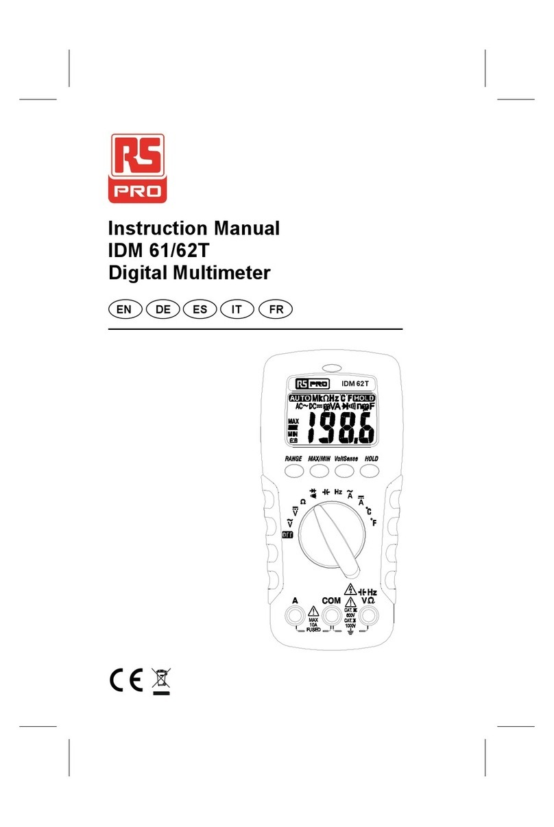
RS IDM 503 User manual

EN
Instruction Manual
IDM 503 & IDM 505
Digital Multimeters
IDM 505

IDM 503 / 505 English
2
SECTION 1 –SAFETY INFORMATION
Safety Information
Understand and follow operating instructions carefully.
Use the Instrument only as specied in this manual; otherwise, the protection provided
by the Instrument may be impaired.
WARNING
Identies hazardous conditions and actions that could cause BODILY HARM or DEATH
CAUTION
Identies conditions and actions that could DAMAGE the Instrument or equipment
under test
WARNING
- Examine the instrument and probes before use. Do not use the instrument
if it is wet or damaged
- When using test leads or probes, keep your ngers behind the nger guards.
- Remove the test lead from the instrument before opening the battery cover
or instrument case.
- Always use the correct terminals, switch position and range for measurements.
- Never attempt a voltage measurement with the test leads inserted into the
“A”input terminals.
- Verify the instrument is operating correctly by measuring a known voltage
- before use. If in doubt, have the instrument serviced.
- Do not apply more than the rated voltage, as marked on the instrument,
between terminals or between any terminal and earth ground.
- Do not attempt a current measurement when the open-circuit voltage is above
the fuse protection rating.
- Only replace a fuse with the correct type and rating as specied in this instruction
manual.
- Use caution when measuring voltages above 30 Vac rms, 42 Vac peak or 60
Vdc. These voltages pose a shock hazard.
- To avoid false readings that can lead to electric shock, replace the battery as
soon as the low battery indicator appears in the display.
- Disconnect the circuit power and discharge all high-voltage capacitors before
making resistance, current, continuity, diode or capacitance measurements.
- Do not use the instrument in a hazardous area or around explosive
gasses or vapours.
- Wear suitable personal protective equipment when working around or near
hazardous live conductors which could be accessible.

IDM 503 / 505 English
3
CAUTION
• Disconnect the test leads from the test points before changing the position
of the function rotary switch.
• Never connect a source of voltage with the function rotary switch in the
“Ω”, “ ” , “°C” , “mA”, or “A” position.
• Do not expose the instrument to extremes in temperature or high humidity.
• Never set the instrument in the “Ω”, “ ” , “°C” , “mA”, or “A” position to measure
the voltage of a circuit, this could result in damage the instrument and the
equipment under test.
Symbols as marked on the instrument and instruction manual
Maintenance
Do not attempt to repair this instrument. It contains no user serviceable parts.
Repair or servicing should only be performed by qualied personnel.
Risk of electric shock
See instruction manual
DC measurement
Equipment protected by double or reinforced Insulation
Battery
Fuse
Earth
AC measurement
Conforms to EU directives
Dispose of in accordance with local regulations.

IDM 503 / 505 English
4
Unsafe Voltage
To alert you to the presence of a potentially hazardous voltage when the rotary switch is in
V or mV position symbols are displayed as detailed in the table below:
Hazardous voltage in 503
IDM503
Function Range Input Mode
Auto Test AC DC AC+DC
mV
40.00mV
0 - 40mVac Reading Reading N/A Reading
>40mVac ‒OL N/A OL
0 - 40mVdc Reading N/A Reading Reading
>40mVdc ‒ N/A OL OL
400.0mV
0 - 40mVac ‒ Reading N/A Reading
40 - 400mVac Reading Reading N/A Reading
>400mVac OL OL N/A OL
0 - 40mVdc ‒ N/A Reading Reading
40 - 400mVdc Reading N/A Reading Reading
>400mVdc OL N/A OL OL
V
4.000V
0 - 4Vac Reading Reading N/A Reading
>4Vac ‒ OL N/A OL
0 - 4Vdc Reading N/A Reading Reading
>4Vdc ‒ N/A OL OL
40.00V
0 - 4Vac ‒ Reading N/A Reading
4 - 30Vac Reading Reading N/A Reading
30 - 40Vac Reading Reading N/A Reading
>40Vac ‒ OL N/A OL
0 - 4Vdc ‒ N/A Reading Reading
4 - 30Vdc Reading N/A Reading Reading
30 - 40Vdc Reading N/A Reading Reading
>40Vdc ‒ N/A OL OL
400.0V
0 - 30Vac ‒Reading N/A Reading
30 - 40Vac ‒ Reading N/A Reading
40 - 400Vac Reading Reading N/A Reading
>400Vac ‒ OL N/A OL
0 - 30Vdc ‒ N/A Reading Reading
30 - 40Vdc ‒ N/A Reading Reading
40 - 60Vdc Reading N/A Reading Reading
60 – 400Vdc Reading N/A Reading Reading
>400Vdc ‒ N/A OL OL
1000V
0 - 30Vac ‒Reading N/A Reading
30 - 400Vac ‒ Reading N/A Reading
400 - 1000Vac Reading Reading N/A Reading
>1000Vac OL OL N/A OL
0 - 30Vdc ‒ N/A Reading Reading
30 - 60Vdc ‒ N/A Reading Reading
60 - 400Vdc ‒ N/A Reading Reading
400 - 1000Vdc Reading N/A Reading Reading
>1000Vdc OL N/A OL OL
0
0
0
0 0
0
0
0
0
0 0
00
0
0
0
0
0
0
0
0
0
0
0
0
0
0
0
0 0 0
0
00
0
0
0
000
0
00
0
0
0
00
0
00
00

IDM 503 / 505 English
5
Note: This symbol “-” indicates that the measurement does not show in the display.
The symbol “N/A” indicates that the measurement is unspecied.
Hazardous voltage in 505
IDM505
Function Range Input Mode
Auto Test AC DC AC+DC
mV
100.00mV
0 - 100mVac Reading Reading N/A Reading
>100mVac - OL N/A OL
0 - 100mVdc Reading N/A Reading Reading
>100mVdc - N/A OL OL
1000.0mV
0 - 100mVac - Reading N/A Reading
100 - 1000mVac Reading Reading N/A Reading
>1000mVac OL OL N/A OL
0 - 100mVdc - N/A Reading Reading
100 - 1000mVdc Reading N/A Reading Reading
>1000mVdc OL N/A OL OL
V
10.000V
0 - 10Vac Reading Reading N/A Reading
>10Vac - OL N/A OL
0 - 10Vdc Reading N/A Reading Reading
>10Vdc - N/A OL OL
100.00V
0 - 10Vac - Reading N/A Reading
10 - 30Vac Reading Reading N/A Reading
30 - 100Vac Reading Reading N/A Reading
>100Vac - OL N/A OL
0 - 10Vdc - N/A Reading Reading
10 - 30Vdc Reading N/A Reading Reading
30 - 60Vdc Reading N/A Reading Reading
60 - 100Vdc Reading N/A Reading Reading
>100Vdc - N/A OL OL
1000.0V
0 - 30Vac - Reading N/A Reading
30 - 100Vac - Reading N/A Reading
100 - 1000Vac Reading Reading N/A Reading
>1000Vac OL OL N/A OL
0 - 30Vdc - N/A Reading Reading
30 - 60Vdc -N/A Reading Reading
60 - 100Vdc -N/A Reading Reading
100 - 1000Vdc Reading N/A Reading Reading
>1000Vdc OL N/A OL OL
0 0
00
000
000
00
00
00
00
000
000
0 0
0
0
0
0
000
0
000
0
000
0

IDM 503 / 505 English
6
Cleaning
Periodically wipe the case with a dry cloth and detergent.
Do not use abrasives or solvents.
SECTION 2 - METER DESCRIPTION
Instrument Description
Front Panel Illustration
1. LCD display : 4000/40000 counts for IDM503.
10000/100000 counts for IDM505.
2. Push-buttons.
3. Rotary switch to turn the power on or off and to select a function.
4. Input Terminal for “A” (current measurement)
5. Input Terminal for “V”, “Ω”, “ ”, Hz, and °C functions.
6. Common (ground reference) input terminal.
7. Input terminal for mA current measurement.

IDM 503 / 505 English
7
Making Basic Measurements
SECTION 3 – METER DESCRIPTION
Preparation and caution before measurement
Observe all warnings and cautions
When connecting the test leads to the device under test connect the common test lead
before connecting the live lead ; when removing the test leads remove the test live lead
before removing the common test lead.
The gures on the following pages show how to make basic measurements.
Measuring AC / DC Voltage

IDM 503 / 505 English
8
High Frequency Reject mode (HFR)
The HFR mode measures the voltage through a low pass lter to reject the high frequency.
The –3dB point of the low pass lter is 800 Hz. The HFR mode can be used when the
rotary switch is in the “V”, “mV” position. To use HFR mode, press the “HFR” button.
Measuring Resistance / Continuity / Diode Capacitance
Testing Continuity

IDM 503 / 505 English
9
Diode Testing
Measuring AC/DC Current
Press the blue button to select the measuring function (AC/DC/AC+DC)

IDM 503 / 505 English
10
Measuring Frequency
Press the blue button to select the measuring function. (Period/Duty)
Measuring Temperature °C / °F
Press the blue button to select the measuring function. (°C / °F)

IDM 503 / 505 English
11
DIGIT:
Press the “DIGIT” button to select the display digit.
AUTO HOLD
In the Auto Hold function, the instrument holds the reading and the current reading
appears on the upper display. When the difference of the held value and the current value
is above 20 counts, the instrument beeps and holds the new value. To use the Auto Hold
mode, press the “A-HOLD” button.

IDM 503 / 505 English
12
Peak HOLD (ACV / ACA Only)
In the Peak Hold function, the instrument records the peak minimum value and the peak
maximum value; when the inputs go below the recorded peak minimum value or above the
recorded peak maximum value, the Instrument records the new value. To use the Peak
HOLD mode, press the “P-HOLD” button.
Sub-Functions navigation option
Sub-Functions item
Navigation : Select the Sub-function item.
Buttons
Navigation : Select the Sub-function item.
ENTER : Enter the Sub-function.
CANCEL : Exit the function.

IDM 503 / 505 English
13
STORE and RECALL
The store function records the input values to memory and recalls them from
memory after. Up to 1000 readings can be stored and recalled.

IDM 503 / 505 English
14
MAX / MIN / AVG
The MAX/MIN/AVG mode records the minimum and maximum input values. When the
inputs go below the record minimum value or above the record maximum value, the
Instrument records the new value. The MAX/MIN/AVG mode can also calculate the
average of the maximum value and the minimum value.

IDM 503 / 505 English
15
dB and dBm (ACV / ACmV only)
The decibel (dB) is a logarithmic unit of measurement that expresses the magnitude of a
physical quantity relative to a specied or implied reference level. The dB and dBm are
dened below.
dB = 20 log
dBm = 20 log
VAC
1
VAC
0.7746

IDM 503 / 505 English
16
Relative mode
In the relative mode, the instrument records the current input value as the reference and
appears on the upper display. For subsequent input values the instrument will calculate the
difference (Δ) between the reference value and the input value or the difference percent
(%) between the reference value and the input value.

IDM 503 / 505 English
17
SECTION 4 – SETUP OPTIONS
Press ▲ or ▼ changes the instrument setting.
Press “ENTER” to store the setting in memory.
Press ◄ or ► select the instrument setting item.
Press “CANCEL” to exit this function.
Beeper
Set the beeper to be ON or OFF.
Auto Power Off (APO)
Setup the auto power off (APO) time from 1 to 60 minutes or off.

IDM 503 / 505 English
18
Back Light Auto OFF
Setup the back light Auto OFF time from 1 to 60 minutes.
HAZARD
Set the hazardous voltage (≧60VDC or ≧30VAC) alarm beeper to ON or OFF.
RESET
Reset all setup values to the factory default.

IDM 503 / 505 English
19
LOG RATE
Setup the logging rate from 0.5 to 600 seconds.
DATALOG
The datalog mode records successive input values to memory and recalls them from
memory afterwards. Up to 20000 values can be recorded in the memory.
Connection to a PC
1. Turn on the meter, and use the USB cable to connect the meter with PC.
2. Put the software CD into the CD-ROM of PC, then install the program
and USB cable driver.
3. Run the program, the program will auto connect with the meter.

IDM 503 / 505 English
20
Auto Power Off
Wake up the instrument by switching the rotary switch or by pressing any button.
Auto Backlight
The backlight is automatically turned on in a dark environment.
Buzzer
The instrument buzzer beeps once for every valid key-press, and beeps twice for every
invalid key-press.
Power On Options
Press the following button while turning the Instrument on from the “OFF” position.
“CANCEL” button : Clear all stored data
“RANGE” button : Display LCD test frame
“FUNCTION” button : Default °C / °F reading
“HFR” button : Display rmware version
“A-HOLD” button : Disable AUTO BACKLIGHT
AUTO BACKLIT AUTO BACKLIT
This manual suits for next models
1
Table of contents
Other RS Multimeter manuals