Timber Tuff Tools TMG-243PT User manual

Page 1of 26
STUMP GRINDER
OWNER’S MANUAL
WARNING: Read carefully and understand all INSTRUCTIONS before
operating. Failure to follow the safety rules and other basic safety
precautions may result in serious personal injury.
20230415 Model # TMG-243PT

Page 2of 26
TABLE OF CONTENTS
TABLE OF CONTENTS 1
INTRODUCTION 3
INTENDED USE 4
TECHNICAL SPECIFICATIONS 4
TOOLS REQUIRED 4
OVERALL DIMENSIONS 5
3-POINT HITCH DIMENSIONS 6
GENERAL SAFETY RULES 7
WORK AREA / PERSONAL SAFETY 8
MACHINE USE AND CARE 10
1. DEFLECTOR 10
2. MANUAL TUBE 11
SET-UP PROCEDURES 12
TRIMMING THE PTO SHAFT 13
PTO SHAFT CLUTCH RUN-IN 15
FLYWHEEL TOOTH TORQUING 16
EQUIPMENT OPERATION 17
STUMP GRINDING PROCEDURE 20
INCORRECT GRINDING PROCEDURES 21
PULLING THROUGHTHE CENTRE
21
GRINDING LEFT-TO-RIGHT
21
CHAINSAW HOLDER 22
STORAGE 22
MAINTENANCE 23
REPLACING TEETH 23
DIAGRAM & PARTS LIST 25
WARRANTY 25
NOTES 26

Page 3of 26
OWNER'S RECORD
Please take a moment to record the following information about your stump
grinder. If you need to call for assistance, please be ready to provide your
model and serial numbers. This information will allow us to help you more
quickly when you call.
MODEL NUMBER
SERIAL NUMBER
DATE OF PURCHASE
INTRODUCTION
Thank you very much for choosing this product! For future reference, please complete the owner’s
record below:
Save the receipt and these instructions. It is important that you read the entire manual to become
familiar with this product before you begin using it.
This machine is designed for certain applications only. We strongly recommend that this
machine not be modified and/or used for any application other than that for which it was
designed.If you have any questions relative to a particular application, DO NOT use the machine
until you have first contacted us to determine if it can or should be performed with the product.
For technical questions and replacement parts, please call 1-218-943-6290.

Page 4of 26
INTENDED USE
This stump grinder is designed for grinding stumps.
TECHNICAL SPECIFICATIONS
Item
Specification
Recommended Horsepower
20 - 45 hp
Flywheel Diameter
24" (610 mm)
Number of Teeth
34
Tooth
Grade 8.8 Carbide Steel, Bolt-in
Tooth Torque Specification
160 ft•lb (215 N•m)
Required PTO Speed
540 rpm
Maximum Cutting Depth Per Pass
5" (127 mm)
Maximum Depth Below Grade
6" (152 mm)
TOOLS REQUIRED
Tool
Specification
Use
Phillips Head Screwdriver
No. 3
Assembly
Wrench/Socket
13 mm (2X)
Assembly
Wrench/Socket
16 mm (2X)
PTO Clutch Run-In
Wrench/Socket
17 mm
PTO Clutch Lock Pin
Wrench/Socket
24 mm
Tooth Replacement
Torque Wrench
Capable of 160 ft•lb (215 N•m)
Multiple
Calliper*
Vernier, Dial, or Digital
PTO Clutch Run-In
Hacksaw**
PTO Trimming
Coloured Pencil/Marker
PTO Clutch Run-In
* Recommended but not required.
** Only if PTO shaft requires trimming. See Trimming the PTO Shaft section for more detail.
Page 5of 26
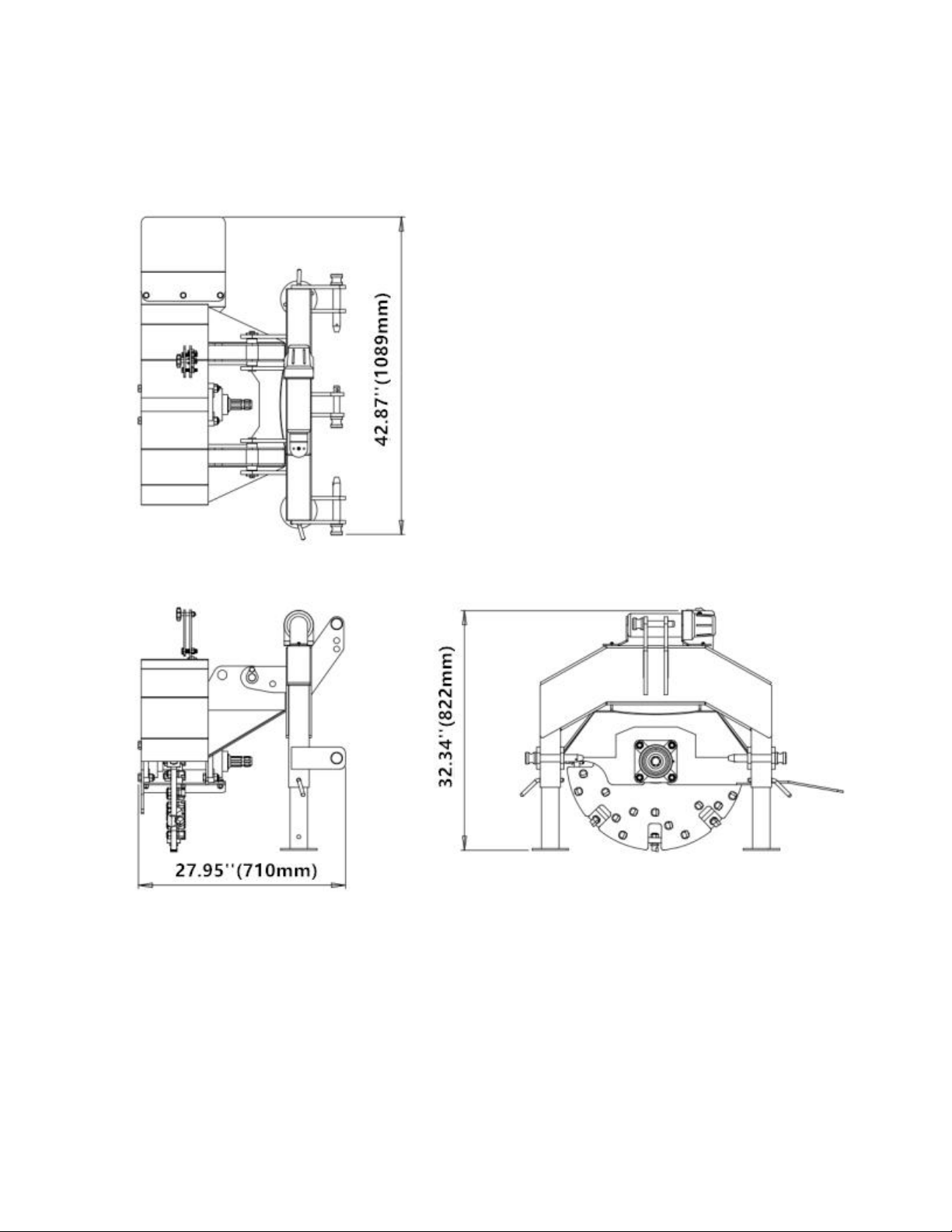
OVERALL DIMENSIONS
Page 6of 26
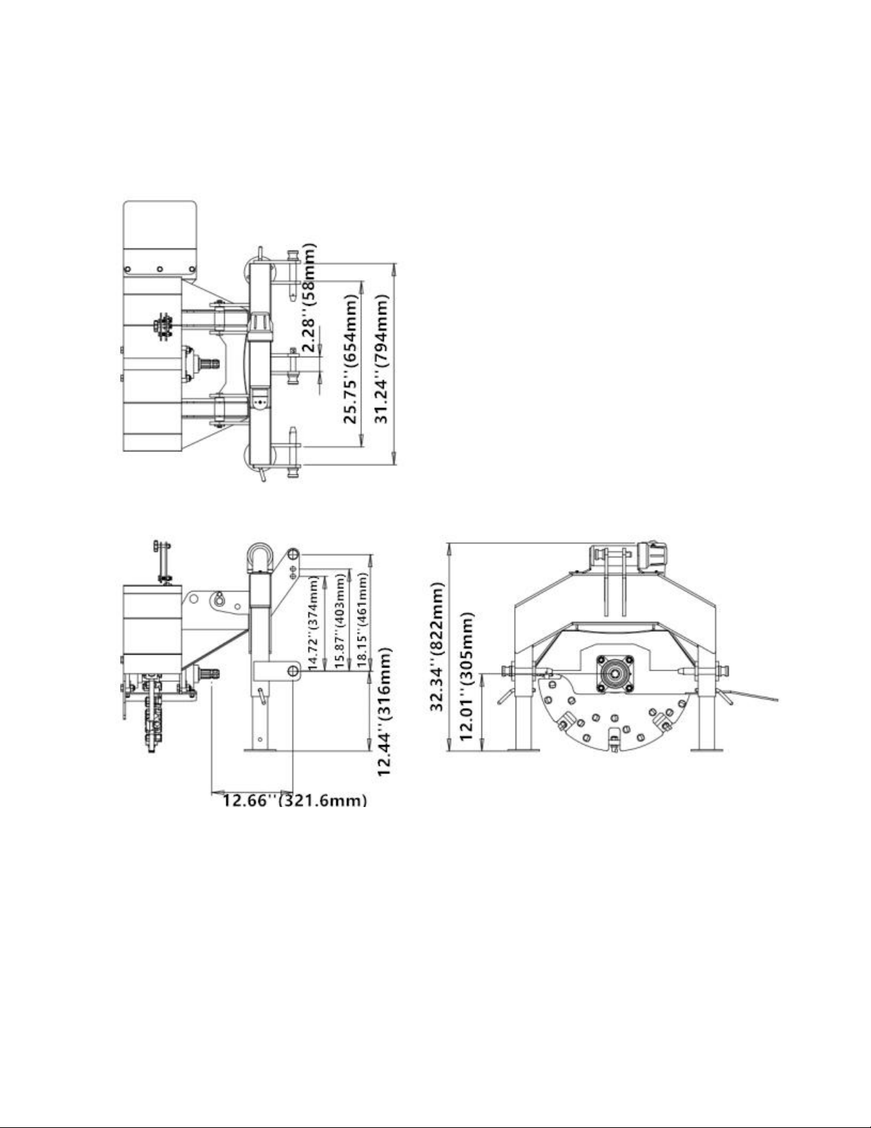
3-POINT HITCH DIMENSIONS

Page 7of 26
WARNING!
Read and understand all instructions. Failure to follow all instructions
listed below may result in electric shock, fire, and/or serious injury.
GENERAL SAFETY RULES
WARNING!
The warnings, cautions, and instructions discussed in this instruction
manual cannot cover all possible conditions or situations that could
occur. It must be understood by the operator that common sense and
caution are factors which cannot be built into this product but must be
supplied by the operator.
•All Federal and State laws and any regulation having jurisdiction covering the safety
requirements for use of the machine take precedence over the statements in this manual.
Users of this machine must adhere to such regulations.
•Only people that have read and understood these instructions are permitted to use the stump
grinder.
•Inspect the stump grinder and tractor at the beginning of every working day and repair any
defects.
•Stop the engine and make sure that the machine will not start accidentally while repairing
defects or performing maintenance.
•Do not disable or remove the stump grinder’s safety devices.
•Always locate and mark buried wires, cables, and pipelines prior to grinding.

Page 8of 26
WORK AREA
•Keep work area clean, free of clutter, and well lit. Cluttered and dark work areas can cause
accidents.
•Keep children and bystanders away while operating a machine. Distractions can cause you to lose
control, so visitors should remain at a safe distance from the work area.
•Be alert of your surroundings. Using a machine in confined work areas may put you dangerously
close to sharp tools and rotating parts.
PERSONAL SAFETY
•Stay alert, watch what you are doing and use common sense when operating machinery. Do
not use a machine when you are tired or under the influence of drugs, alcohol, or medication.
A moment of inattention while operating machinery may result in serious personal injury.
•Dress properly. Do not wear loose clothing, dangling objects, or jewelry. Keep your hair,
clothing, and gloves away from moving parts. Loose clothes, jewelry, or long hair can be
caught in moving parts. Air vents often cover moving parts and should be avoided.
•Use safety apparel and equipment. Use safety goggles or safety glasses with side shields
which comply with current national standards, or when needed, a face shield. Use a dust
mask in dusty work conditions. This applies to all persons in the work area. Also use non-
skid safety shoes, hardhat, gloves, dust collection systems, and hearing protection when
appropriate.
•Do not overreach. Keep proper footing and balance at all times.
•Remove adjusting keys or wrenches before connecting to the power supply or turning on
the machine. A wrench or key that is left attached to a rotating part of the machine may result
in personal injury.
•Never conduct any maintenance or make any other adjustments while the tractor
engine is running. Always shut the tractor engine off, remove the ignition key, and keep the
engine off before carrying out any of the following procedures. Consult your tractor’s operator
manual for safe shutdown procedures to prevent accidental ignition.
•Never allow passengers to ride on the stump grinder.

Page 9of 26
STUMP GRINDER USE AND CARE
•Always be sure the operator is familiar with proper safety precautions and operation
techniques before using the stump grinder.
•Do not force the stump grinder. Stump grinder do a better and safer job when used in the
manner for which they are designed.
•Storing the stump grinder. When the stump grinder is not in use, store it in a dry, secure
place or keep it well-covered and out of the reach of children. Inspect the stump grinder for
good working condition prior to storage and before each use.
•Maintain the stump grinder. It is recommended that the general condition of the stump
grinder be examined before it is used. Keep your machine in good working order by adopting
a program of conscientious repair and maintenance in accordance with the recommended
procedures found in this manual. If any abnormal vibrations or noise occurs, turn the machine
off immediately and have the problem corrected before further use.
•Cleaning. Use a pressure washer to clean the carbide teeth while taking care not to
pressure-wash the bearings as this could introduce water into areas of the stump grinder that
may cause malfunction or damage.
•Use only accessories that are recommended by the manufacturer. Accessories that may
be suitable for another machine may create a risk of injury when used on this stump grinder.
•Always operate the stump grinder with all safety devices and guards in place and in good
working order. DO NOT modify or make changes to safety devices. DO NOT operate the
stump grinder if any safety devices or guards are missing or inoperative.
•Never leave the stump grinder running unattended.
•Never use the machine to grind anything other than stumps or for any purpose other
than grinding stumps as described in this manual.

Page 10 of 26
ASSEMBLY
1. DEFLECTOR
Using the hardware listed below and two (2) 13 mm sockets/wrenches, assemble the deflector (#25) to
the flywheel housing as shown.
3x
M10 X 35 mm
Hex Bolt
#39
3x
M10 Flat
Washer
#47
3x
M10 Lock Nut
#52
1x
Deflector
#25

Page 11 of 26
2. MANUAL TUBE
Using the hardware listed below and a No. 3 Phillips head screwdriver, assemble the manual tube
(#46) to the back frame as shown. Remove the cap from the manual tube (#46) to gain access to the
center mounting hole.
2x
M6 X 20 mm
Phillips Pan
Head Screw
#50
2x
M6 Flat
Washer
#48
2x
M6 Split Lock
Washer
#49
1x
Manual Tube
#46

Page 12 of 26
A
SET-UP PROCEDURES
TRIMMING THE PTO SHAFT
The stump grinder is shipped with a slip clutch PTO shaft that can be fitted to most Category 1
tractors. The PTO shaft may need to be trimmed depending on your tractor and configuration.
Follow the steps below to ensure the PTO shaft is correctly fitted to your tractor.
**Note: the slip clutch end of the PTO shaft mounts to the stump grinder.**
1. Attach the stump grinder to the tractor’s 3-point hitch system. Do not install the PTO shaft.
2. Raise the stump grinder so that the shaft on the tractor is in line with the shaft on the stump
grinder.
3. Measure the distance between the locking grooves on the splined shafts of the tractor and
stump grinder (Dim A) as shown below:
Stump Grinder
Tractor

Page 13 of 26
B
Remove burrs from
inner edge of outer
telescoping shaft
after trimming
Remove burrs from
outer edge of inner
telescoping shaft
after trimming
4. Verify the distance between the locking pins on the PTO shaft while in the compressed state
(Dim B) as shown in the image below. It should measure 34” (862.5 mm).
5. If Dim A is at least 1” (25 mm) longer than Dim B, the PTO shaft does not require trimming.
It is recommended the shaft not be used if there is less than 6” (150 mm) of overlap
between the two halves of the PTO shaft when the equipment is in the operating position.
6. If Dim B is longer than Dim A, the PTO shaft will require trimming. Use this equation to
calculate the correct amount to trim:
(B - A) + 1 inch = C (Amount to Trim)
7. Once Chas been calculated, trim that amount from BOTH halves of the PTO shaft safety
cover first, then trim the same amount from both shafts. This will ensure the safety cover on
each end remains a few inches back from the ends of the shafts, otherwise PTO shaft
reassembly could be difficult.
8. After trimming both halves of the PTO shaft, use a file to remove any burrs or sharp edges
and slide the halves back together, ensuring they telescope in-and-out freely. The PTO
shaft is now ready to connect the stump grinder to the tractor for operation.
Page 14 of 26
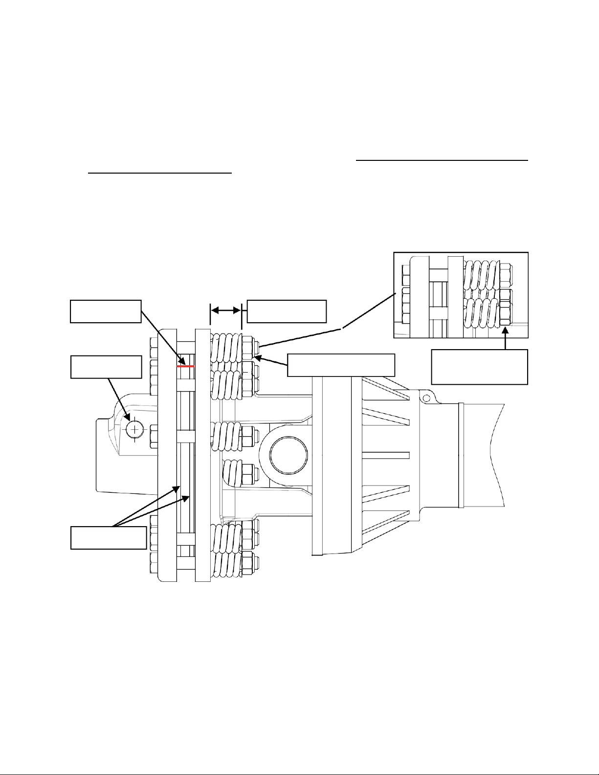
Spring Tension Nut
Spring Height
Fig. A: Nuts flush
with bolt ends
Clutch Plates
Locking Pin
Scribe Line
PTO SHAFT CLUTCH RUN-IN
The stump grinder is shipped with a slip clutch PTO shaft. Follow the steps below before using
your stump grinder to ensure the PTO shaft clutch plates are set properly.
1. Connect the PTO shaft to the stump grinder and tractor with the clutch end of the PTO shaft
mounted to the stump grinder. Insert the locking pin on the clutch yoke and tighten the nut
using a 17 mm wrench or socket.
2. Using a coloured pencil or marker, scribe a line across the exposed edges of the clutch
plates.
3. Using a 16 mm wrench or socket, loosen all 8 spring tension nuts uniformly until the ends of
the nuts are flush with the ends of the bolts (Fig. A).
4. Start the tractor and engage the PTO for 2-3 seconds to permit slippage of clutch surfaces.
Disengage the PTO then re-engage a second time for 2-3 seconds. Disengage the PTO
again, shut off the tractor, and remove the key. Wait for all components to stop rotating
before removing the PTO shaft from tractor.
5. Inspect the clutch and ensure that the scribed markings made across the clutch plates have
changed position. Slippage has not occurred if the two marks on the clutch plates are still
aligned. A clutch that has not slipped must be disassembled to separate the clutch plates.

Page 15 of 26
0
inch
0
1
2
8
3
9
4
5
6
0
1 2 3 4 5 6 7
10 11 12 13 14 15 16 17
cm
012345678901/20
Typical vernier calliper
1/128
8
4
6. Tighten all 8 nuts until the proper spring height dimension values are achieved per the “PTO
Shaft Clutch Spring Height vs. Horsepower” table for your PTO output horsepower. It is
recommended that a calliper (either digital, dial, or vernier—similar to the one shown below)
be used to accurately verify the spring height measurements. After setting all 8 spring
heights, the clutch is now ready for use.
PTO Shaft Clutch Spring Height vs. Horsepower
PTO Shaft Clutch Flange Dia PTO hp Spring Height
5S.FF2
7-⅝” (200 mm)
20 hp
1.26” (31.9 mm)
25 hp
1.25” (31.7 mm)
30 hp
1.24” (31.4 mm)
35 hp
1.22” (31.1 mm)
45 hp
1.20” (30.5 mm)
All ratings are at 540 rpm PTO speed
7. The clutch should be checked during the first hour of use and periodically each week
thereafter. Excessive clutch plate slippage, burning odor, or visible smoking should not be
observed during use.
Page 16 of 26
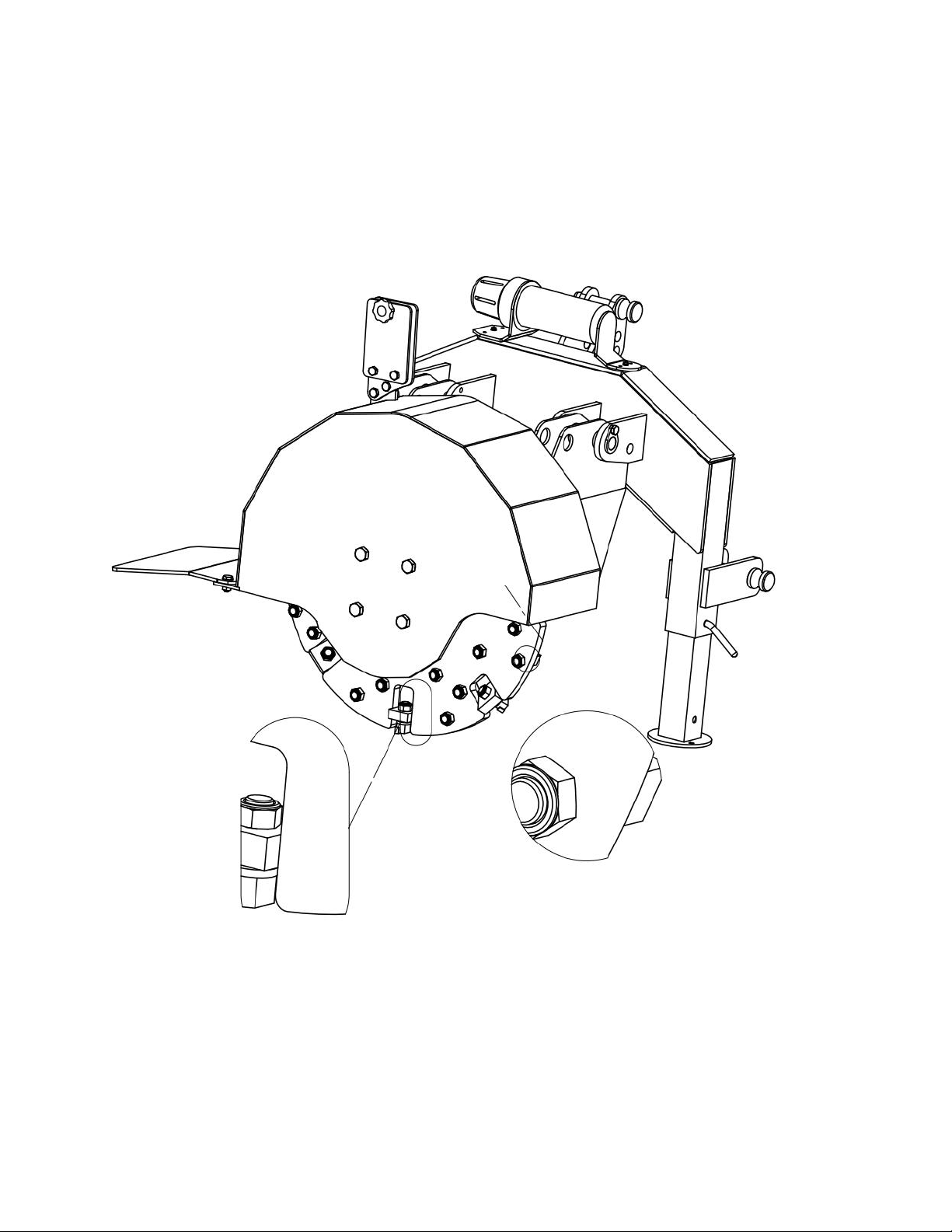
FLYWHEEL TOOTH TORQUING
Prior to operation, ensure all 34 teeth (#18) are torqued to 160 ft•lb (215 N•m) using a torque
wrench with a 24 mm socket.
Page 17 of 26
WARNING!
To avoid death or serious injury, do not grind stumps containing
embedded foreign objects such as nails, wire, metal fragments, etc.
EQUIPMENT OPERATION
1. Wear heavy-duty work gloves, ANSI-approved goggles behind a full face shield, steel-toed
work boots, and a dust mask.
2. Securely attach the stump grinder to the tractor’s 3-point hitch system and install the PTO
shaft.
3. Prior to each daily use, check all 34 teeth (#18) and ensure they are not loose, missing, or
damaged, and are torqued to the proper specification. Torque any undamaged loose teeth
to 160 ft•lb (215 N•m) using a torque wrench with a 24 mm socket.
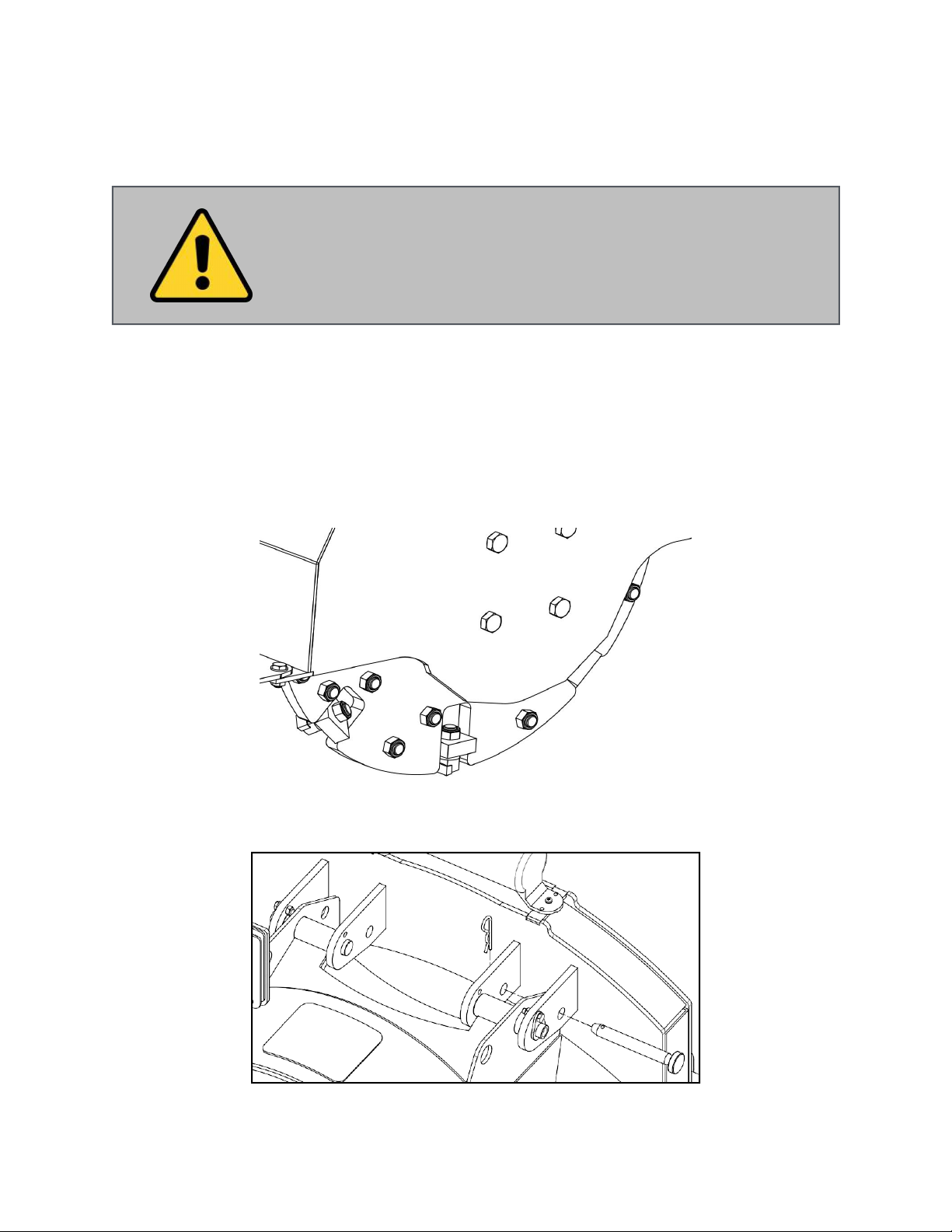
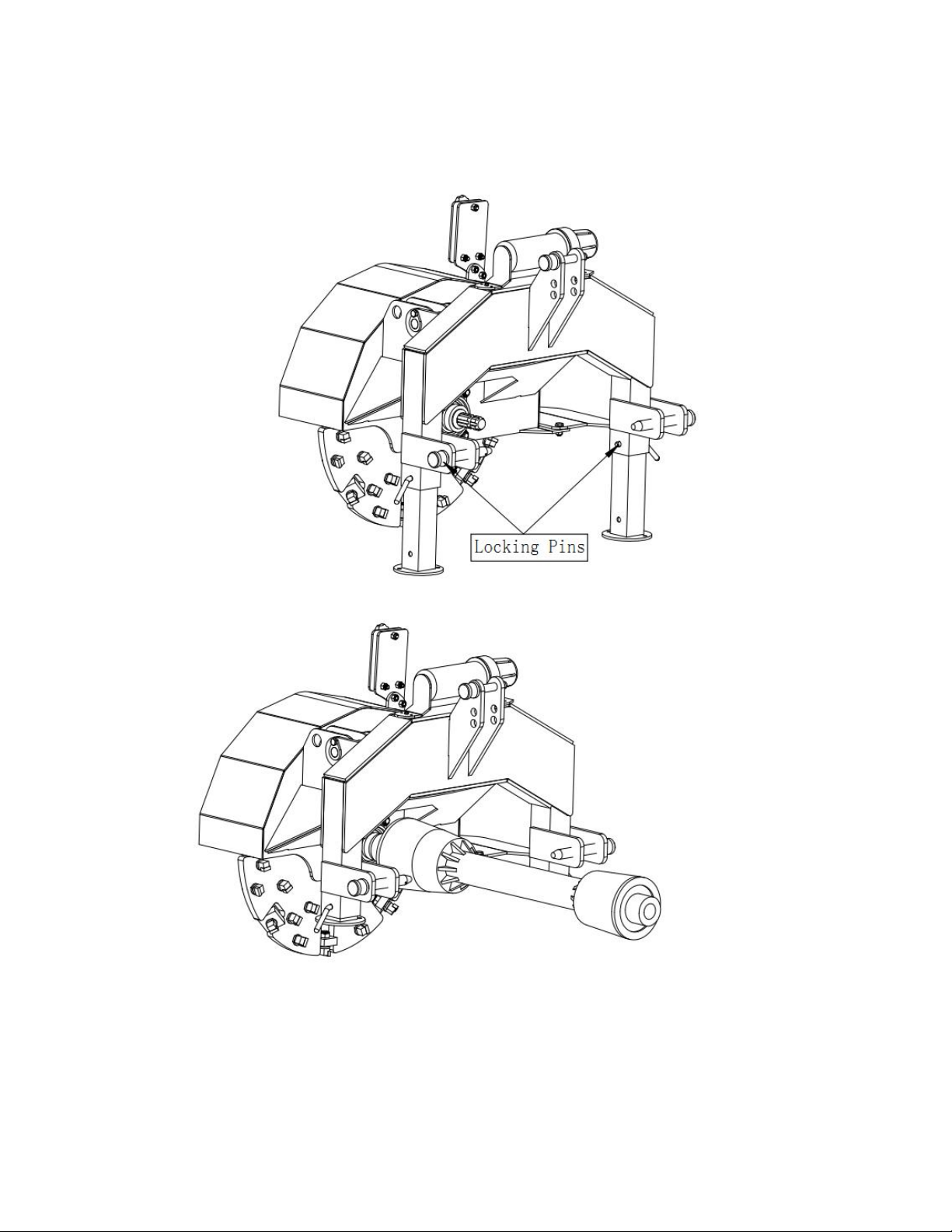
4. Remove the stabilizer pin (# 51) prior to operation as shown below:
Page 18 of 26
5. Remove the leg locking pins (#37), slide the legs (#13) up inside the tubes of the back
frame (#15), and reinstall the locking pins (#37) to secure them in place.
6. Reverse over a tree stump and lower the stump grinder so it will remove 2" (50 mm) per
pass. Always ensure the grinder is cutting properly and not jumping around erratically.
Read pages 20-21 on proper stump grinding procedures.
Page 19 of 26
7. Once the stump is at ground level, continue to take up to 2” (50 mm) deep passes until the
stump and roots are 4-6” (100-150 mm) below grade. Keep a watch out for foreign objects
below the soil like rocks or buried metal. These can damage or break the teeth resulting in
poor grinding performance.
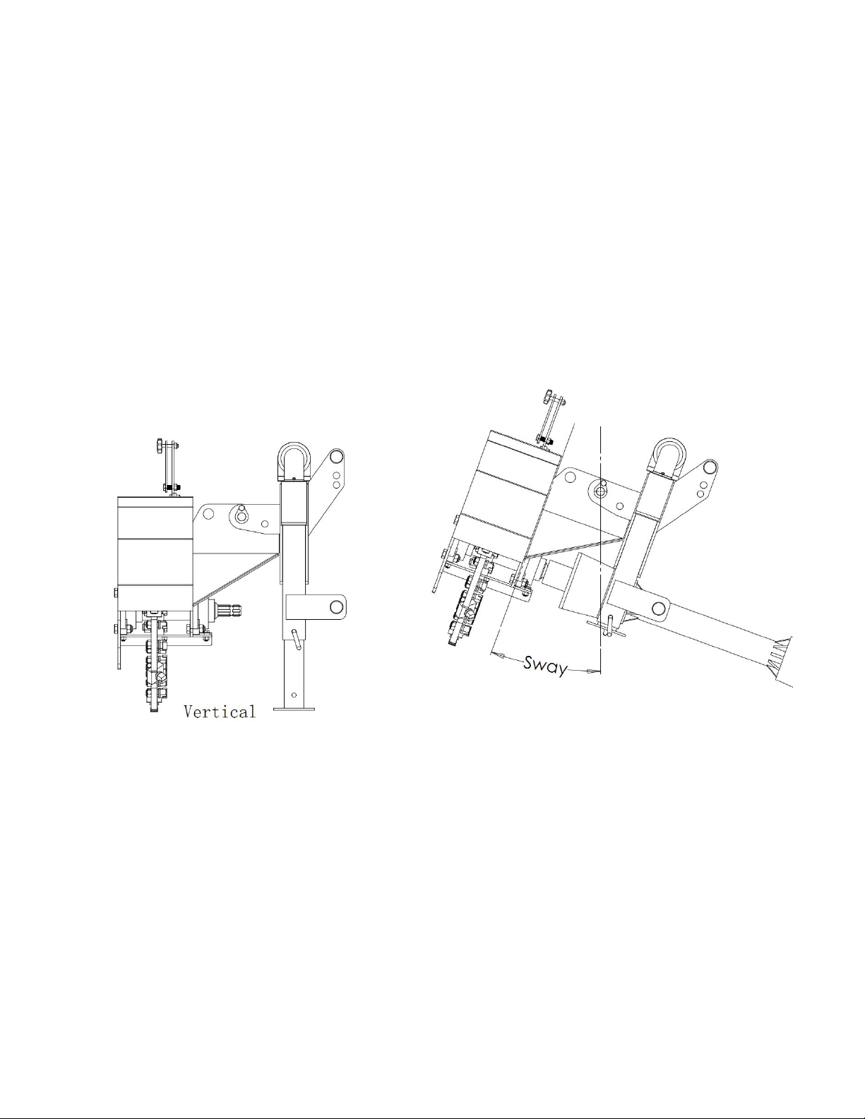
8. During use, it is important to never let the stump grinder sway beyond an angle that will
allow the PTO shaft to separate. Do not operate the stump grinder with less than 6” (150
mm) of overlap between the two halves of the PTO shaft. If the stump grinder begins to
sway, it means either the tractor is advancing faster than the grinder can remove material or
that too much material is being removed per pass. If this is observed, immediately stop
moving forward and position the tractor and stump grinder in a manner so that it is in the
vertical position. Take a slower pass and/or shallower cut if necessary.
Page 20 of 26
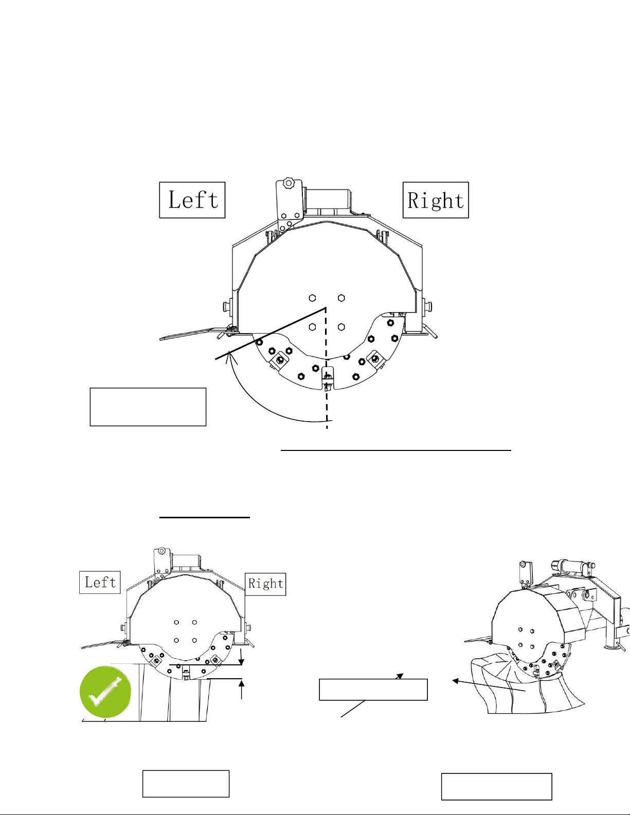
STUMP GRINDING PROCEDURE
The flywheel spins in a clockwise manner (when facing the rear of the machine) with the
effective cutting area in the lower-left quadrant as shown below:
Therefore, when grinding a tree stump, always start from the right side of the stump, moving
incrementally to the left, pulling the grinder straight forward through the stump on each pass.
When grinding softwoods like pine, spruce, or poplar, it may be permissible to remove upwards
of 2” (50 mm) of material per pass. However, hardwoods like oak, ash, and birch can be much
more dense and the depth of grind may only be up to 1” (25 mm). If the chassis is swaying like
described in the previous section, or the grinder is vibrating or bouncing, reduce the depth of
cut or feed rate accordingly.
Depth of Grind
Effective cutting
area
Direction of Grind
Grind Progression
Table of contents
Popular Grinder manuals by other brands

EINHELL
EINHELL bavaria BD 150 operating instructions

Bosch
Bosch GGS Professional 8 CE Original instructions

EINHELL
EINHELL TC-AG 18/115 Li Original operating instructions

Sunex HD
Sunex HD SX5245 instruction manual

Scheppach
Scheppach DS920X Translation of original instruction manual

tresnar
tresnar TAG-230/2380 instruction manual

Bosch
Bosch GWS 8-115 Professional Original instructions

Makita
Makita M9511 instruction manual

Scheppach
Scheppach bgs 700 Translation of original instruction manual

GÜDE
GÜDE GKS 150-25 Translation of the original instructions

Metabo
Metabo WQ 1400 Original instructions

Meister
Meister WS750-125M Translation of the original instructions


