TimberPro EXZ2610DL User manual

OWNER’S MANUAL
MODE D’EMPLOI
BEDIENUNGSANLEITUNG
GEBRUIKSAANWIJZING
MANUAL DEL PROPIETARIO
MANUALE D’ISTRUZIONI

DE 39-57
FR 20-38
GB 01-19
NL 58-76
ES 77-95
IT 96-114
BRUSHCUTTER
DÉBROUSSAILLEUSE
FREISCHNEIDER
BOSMAAIER
DESBROZADORA
DECESPUGLIATORE

Troubleshooting guide.......................................18
9. Storage..............................................................18
10. Disposal.............................................................18
7. Operation ........................................................ 10
18. Blade
17. Cutting line head
16. Angle transmisson
15. Cutting attachment guard
14. Air filter cover
13. Choke lever
12. Primer
11. Fuel tank
10. Starter knob
9. Spark arrester
3. Stop switch
8. Knob bolt
7. Shaft tube
6. Throttle set button
1. Parts location ................................................... 01
8. Maintenance......................................................15
6. Fuel and chain oil..............................................08
5. Set up.............................................. .................06
4. For safe operation.............................................03
3. Symbols on the machine..................................02
2. Warning labels on the machine........................02
le of Contents
11.
Tab
1. Handle
2. Suspension point
4. Throttle cable
5. Throttle trigger
1. Parts location
Limited Warranty................................................1912.
GB 1
9
13
10
12
14
1
2
3
4
5
6
7
8
11
15
16
17
18

3. Symbols on the machine
2. Warning labels on the machine
For safe operation and maintenance, symbols are carved in relief on the machine. According to these indications,
please be careful not to make a mistake.
The port to refuel the “MIX GASOLINE”
Position: FUEL TANK CAP
The direction to close the choke
Position: AIR CLEANER COVER
The direction to open the choke
Position: AIR CLEANER COVER
Never modify your machine.
We won’t warrant the machine, if you use the
remodeled brushcutter or if you don’t observe
the proper usage written in the manual.
If warning label peels off or becomes soiled and
impossible to read, you should contact the
dealer from which you purchased the product
to order new labels and affix them in the required
location(s).
15m (50ft)
(1) (2) (3) (4) (5) (6) (7)
(1) Read owner’s manual before operating this machine.
(2) Wear head, eye and ear protection.
(3) Wear foot protection.
(4) Wear gloves.
(5) Beware of thrown objects.
(6) Warning / Attention
(7) Keep all children, bystanders and helpers 15 meters away from the machine.
GB 2

4. For safe operation
1. Read this manual carefully until
you completely understand and
follow all safety and operating
instructions.
2. Keep this manual handy so that
you may refer to it later when-
ever any questions arise. Also
note, if you have any questions
which cannot be answered
herein, contact the dealer from
whom you purchased the prod-
uct.
3. Always be sure to include this
manual when selling, lending, or
otherwise transferring the own-
ership of this product.
4. Never allow children or anyone
unable to fully understand the
directions given in the manual
to use the machine.
WORKING CONDITION
1. When using the product, you
should wear proper clothing and
protective equipment.
(1) Helmet
(2) Ear protectors
(3) Protection goggles or face
protector
(4) Thick work gloves
(5) Non-slip-sole work boots
2. And you should carry with you.
(1) Attached tools
(2) Properly reserved fuel
(3) Spare blade
(4) Things to notify your working
area (rope, warning signs)
(5) Whistle (for collaboration or
emergency)
(6) Hatchet or saw (for removal of
obstacles)
3. Do not wear loose clothing, jew-
elry, short trousers, sandals, or go
barefoot. Do not wear anything
which might be caught by a mov-
ing part of the unit. Secure hair
so it is above shoulder length.
WORKING CIRCUMSTANCE
1. Never start the engine inside a
closed room or building. Exhaust
gases contain dangerous carbon
monoxide.
2. Never use the product,
a. when the ground is slippery
or when you can’t maintain a
steady posture.
b. At night, at times of heavy fog,
or at any other times when
your field of vision might be
limited and it would be diffi-
cult to gain a clear view of the
working area.
c. During rain storms, during
lightning storms, at times of
strong or gale-force winds, or
at any other times when
weather conditions might
make it unsafe to use the
product.
WORKING PLAN
1. You should never use the prod-
uct when under the influence of
alcohol, when suffering from ex-
haustion or lack of sleep, when
suffering from drowsiness as a re-
sult of having taken cold medicine
or at any other time when a pos-
sibility exists that your judgment
might be impaired or that you
might not be able to operate the
product properly and in a safe
manner.
2. When planning your work sched-
ule, allow plenty of time to rest.
Limit the amount of time over
which the product is to be used
continuously to somewhere
around 30 ~ 40 minutes per ses-
sion, and take 10 ~ 20 minutes of
rest between work sessions. Also
try to keep the total amount of
work performed in a single day
under 2 hours or less.
WARNING
1. If you don’t observe the working
time, or working manner (See
“USING THE PRODUCT”), Re-
petitive Stress Injury (RSI) could
occur.
If you feel discomfort, redness and
swelling of your fingers or any
other part of your body, see a doc-
tor before getting worse.
2. To avoid noise complaints, in gen-
eral, operate product between
8 a.m. and 5 p.m. on weekdays
and 9 a.m. to 5 p.m. on weekends.
NOTE
Check and follow the local regula-
tions as to sound level and hours of
operations for the product.
GB 3

for repair.
your authorized servicing dealer
4. For safe operation
BEFORE STARTING
THE ENGINE
1. The area within a perimeter of
15 m of the person using the
product should be considered a
hazardous area into which no one
should enter. If necessary, yellow
warning rope, warning signs
should be placed around the pe-
rimeter of the area. When work is
to be performed simultaneously
by two or more persons, care
should also be taken to constantly
look around or otherwise check
for the presence and locations of
other people working so as to
maintain a distance between
each person sufficient to ensure
safety.
2. Check the condition of working
area to avoid any accident by hit-
ting hidden obstacles such as
stumps, stones, cans, or broken
glass.
IMPORTANT
Remove any obstacle before begin-
ning work.
3. Inspect the entire unit for loose
fasteners and fuel leakage. Make
sure that the cutting attachment
is properly installed and securely
fastened.
4. Be sure the cutting attachment
guard is firmly attached in place.
5. Always use the harness. Adjust
the strap for comfort before start-
ing the engine. The strap should
be adjusted so the left hand can
comfortably hold the handlebar
grip approximately waist high.
STARTING THE ENGINE
1. Keep bystanders and animals at
least 15 m away from the operat-
ing point. If you are approached,
immediately stop the engine.
2. The product is equipped with a
centrifugal clutch mechanism, so
the cutting attachment begins to
rotate as soon as the engine is
started by putting the throttle into
the start position. When starting
the engine, place the product
onto the ground in a flat clear area
and hold it firmly in place so as to
ensure that neither the cutting
part nor the throttle come into
contact with any obstacle when
the engine starts.
WARNING
Never place the throttle into the
high-speed position when starting
the engine.
3. After starting the engine, check
to make sure that the cutting at-
tachment stops rotating when the
throttle is moved fully back to its
original position. If it continues to
rotate even after the throttle has
been moved fully back, turn off
the engine and take the unit to
USING THE PRODUCT
IMPORTANT
Cut only materials recommended by
the manufacturer. And use only for
tasks explained in the manual.
1. Grip the handles firmly with both
hands using your whole hand.
Place your feet slightly apart
(slightly further apart than the
width of your shoulders) so that
your weight is distributed evenly
across both legs, and always be
sure to maintain a steady, even
posture while working.
2. Keep cutting attachment below
waist level.
3. Maintain the speed of the engine
at the level required to perform
cutting work, and never raise the
speed of the engine above the
level necessary.
4. If the unit starts to shake or vi-
brate, turn off the engine and
check the whole unit. Do not use
it until the trouble has been prop-
erly corrected.
5. Keep all parts of your body away
from rotating cutting attachment
and hot surfaces.
6. Never touch the muffler, spark
plug, or other metallic parts of the
engine while the engine is in op-
eration or immediately after shut-
ting down the engine. Doing so
could result in serious burns or
electrical shock.
GB 4

er is designed to run on a mixed
The engine of the product we off-
4.
servicing dealer for assistance
from the store nearest authorized
3.
WARNING
Approaching or contacting elec-
tric power lines with pruning saw
may cause serious injury or death
from electrocution.
Electricity can jump from one
point to another by means of arc-
ing or may be conducted through
damp branches. Maintain a clear-
ance of at least 15m between Pole
saw and any electrical line carry-
ing live current.
• IF SOMEONE COMES
1. Guard against hazardous situa-
tions at all times. Warn adults to
keep pets and children away from
the area. Be careful if you are ap-
proached. Injury may result from
flying debris.
2. If someone calls out or otherwise
interrupts you while working, al-
ways be sure to turn off the en-
gine before turning around.
MAINTENANCE
1. In order to maintain your product
in proper working order, perform
the maintenance and checking
operations described in the
manual at regular intervals.
2. Always be sure to turn off the en-
gine and disconnect the spark
plug wire before performing any
maintenance or checking proce-
dures.
WARNING
The metallic parts reach high tem-
peratures immediately after stop-
ping the engine.
In the event that any part must be
replaced or any maintenance or
repair work not described in this
manual must be performed,
please contact a representative
Under no circumstances should
you ever take apart the product
or alter it in any way. Doing so
might result in the product be-
coming damaged during opera-
tion or the product becoming un-
able to operate properly.
HANDLING FUEL
1.
fuel, which contains highly flam-
mable gasoline. Never store cans
of fuel or refill the tank of the unit
in any place where there is a
boiler, stove, wood fire, electrical
sparks, welding sparks, or any
other source of heat or fire which
might ignite the fuel.
2. Never smoke while operating the
unit or refilling its fuel tank.
3. When refilling the tank, always
turn off the engine and allow it to
cool down. Take a careful look
around to make sure that there are
no sparks or open flames any-
where nearby before refueling.
4. Wipe spilled fuel completely us-
ing a dry rag if any fuel spillage
occurs during refueling.
5. After refueling, screw the fuel cap
back tightly onto the fuel tank and
then carry the unit to a spot 3 m
or more away from where it was
refueled before turning on the en-
gine.
TRANSPORTATION
1. When hand-carrying the product,
cover over the cutting part if nec-
essary, lift up the product and
carry it paying attention to the
blade.
2. Never transport the product over
rough roads over long distances
by vehicle without removing all
fuel from the fuel tank. If doing so,
fuel might leak from the tank dur-
ing transport.
4. For safe operation
GB 5

5. Set up
IMPORTANT
3())
*ÿ+(,)
ÿ
-'./ÿÿ01/ÿÿÿ233#ÿ!3ÿ!4ÿ/#ÿÿ
!4/ÿ52!6'ÿ78ÿÿ1/'
9'2ÿÿ!4ÿ!//%16ÿÿÿ1#!&ÿ!4ÿ32ÿÿ
233#ÿ!3ÿ:#ÿ'ÿ8ÿÿ!3ÿ/2#6'ÿ
INSTALLING CUTTING ATTACHMENT GUARD
• Put the cutting attachment guard on the gearbox, at-
tach it with the 2 screws and hardware provided.
8
BRUSH CUTTER AND EDGE TRIMMER
INSTALLING THE NYLON LINE (NYLON
CUTTER HEAD)
INSTALLING METAL BLADE
1- Place the collar rin
g
(3) on the shaft thread.
2- Insert the key wrench (1) into the
g
ear
case lockin
g
hole.
3- Secure metal blade (4) between collar rin
g
(3)
and washer (5).
4- Place the washer (6)
5- Screw the nut (7).
1- key ;
2-
g
ear case ;
3- collar rin
g
;
4- metal blade;
5- washer;
6- washer;
7- nut
1- Place the collar rin
g
(3) on the shaft thread.
2- Insert the key wrench (1) into the
g
ear case
lockin
g
hole.
3- Screw the nylon spool (8) on the shaft thread.
4- Check the spool is secured ti
g
htly
1- Key ;
2-
g
ear case ;
3-collar rin
g
;
8- nylon spool
Before using trimmer head, mount the trimming knife with
3 screws as illustrated below. When the machine is run-
ning, tap the trimmer head on the ground, the trimmer line
will come out automatically. The trimming knife will cut and
keep the trimmer line in correct length.
Trimming knife
•
CONNECTINHG THE SHAFT
A
B
C
To connect the working shaft to the main
shaft,
Loose the turnin
g
nut(A) and
p
ress the
“Push”button(B).
Insert the workin
g
shaft into the
connector and release the “Push ”
button(B),make sure the “Push ”
buttons locks the hole (C) on the
workin
g
shaft.
Secure the turnin
g
nut(A).
•
•
GB 6

5. Set up
(1)
HARNESS
(1)
WARNING
ALWAYS WEAR THE PROVIDED HARNESS WHEN
USING THE MACHINE!
Always make sure the machine is hooked securely
to the harness.
If you don't, you will be unable to control the machine
safely.This can result in injury to yourself or others.
Never use a harness with a defective quick release
or any other damage.
HOW TO WEAR
1. Wear the provided harness without twisted bands, with
the hanger on your right side.
(1) Hanger
BALANCE THE UNIT
1. Hook your machine to the hanger.
2. Adjust the bands of the harness to have the blade
parallel to the ground when standing in your normal
working position to provide you most effectiveness
and comfort on operating the machine.
3. In order to prevent the hanger position to change
during operation, turn up the extra part of the band
from the buckle.
QUICK RELEASE
The harness is equipped with a "QUICK RELEASE"devise.
To release the machine from the harness in emergency
situations, please follow the procedure as explained
below.
WARNING
Make sure to check proper working of the QUICK RE-
LEASE device BEFORE operating the machine.
Make sure to hold the unit securely when using the
QUICK RELEASE.
While holding the unit by your right hand securely, press
both sides of the
buckle. sides of the buckle.
(1) Buckle
4. When correctly adjusted, check the correct working
of the harnesses' QUICK RELEASE.
GB 7

6. Fuel and chain oil
■ FUEL
WARNING
• Gasoline is very flammable. Avoid smoking or
bringing any flame or sparks near fuel. Make sure
to stop the engine and allow it cool before refuel-
ing the unit. Select outdoor bare ground for fueling
and move at least 3 m (10 ft) away from the fueling
point before starting the engine.
25
- ONLY USE UNLEADED 95 FUEL (STANDARD) AND
SYNTHETIC 2-STROKE OIL FOR THE MIXTURE.
MIX 25:1 40:1
Gasoline Oil in ml Oil in ml
1,0 Liter 40 25
1,5 Liter 60 38
2,0 Liter 80 50
2,5 Liter 100 63
3,0 Liter 120 75
3,5 Liter 140 88
4,0 Liter 160 100
4,5 Liter 180 113
5,0 Liter 200 125
5,5 Liter 220 138
6,0 Liter 240 150
6,5 Liter 260 163
7,0 Liter 280 175
7,5 Liter 300 188
8,0 Liter 320 200
8,5 Liter 340 213
9,0 Liter 360 225
9,5 Liter 380 238
10,0 Liter 400 250
10,5 Liter 420 263
11,0 Liter 440 275
11,5 Liter 460 288
12,0 Liter 480 300
12,5 Liter 500 313
13,0 Liter 520 325
13,5 Liter 540 338
14,0 Liter 560 350
14,5 Liter 580 363
15,0 Liter 600 375
15,5 Liter 620 388
16,0 Liter 640 400
16,5 Liter 660 413
17,0 Liter 680 425
■RECOMMENDED MIXING RATIO
GASOLINE 25 : OIL 1
√
GB 8

3. DO NOT USE READY-TO-USE ALKYLATE PETROL, THESE
2. DO NOT USE FUEL TYPE SP95-E10 (10% ETHANOL) TO
6. Fuel and chain oil
•Exhaust emission are controlled by the funda-
mental engine parameters and components (eq.,
carburation, ignition timing and port timing) with-
out addition of any major hardware or the introduc-
tion of an inert material during combustion.
• These engines are certified to operate on unleaded
gasoline.
• If you use a gasoline of a lower octane value than pre-
scribed, there is a danger that the engine tempera-
ture may rise and an engine problem such as piston
seizing may consequently occur.
• Unleaded gasoline is recommended to reduce the
contamination of the air for the sake of your health and
the environment.
• Poor quality gasolines or oils may damage sealing
rings, fuel lines or fuel tank of the engine.
■ HOW TO MIX FUEL
WARNING
•Pay attention to agitation.
1. Measure out the quantities of gasoline and oil to be
mixed.
2. Put some of the gasoline into a clean, approved fuel
container.
3. Pour in all of the oil and agitate well.
4. Pour in the rest of gasoline and agitate again for at
least one minute. As some oils may be difficult to
agitate depending on oil ingredients, sufficient agi-
tation is necessary for the engine to last long. Be
careful that, if the agitation is insufficient, there is an
increased danger of early piston seizing due to ab-
normally lean mixture.
5.
Put a clear indication on the outside of the container
to avoid mixing up with gasoline or other containers.
6. Indicate the contents on outside of container for easy
identification.
■ FUELING THE UNIT
1. Untwist and remove the fuel cap. Rest the cap on a
dustless place.
2. Put fuel into the fuel tank to 80% of the full capacity.
3. Fasten the fuel cap securely and wipe up any fuel
spillage around the unit.
WARNING
1. Select flat and bare ground for fueling.
2. Move at least 10 feet (3 meters) away from the fu-
eling point before starting the engine.
3. Stop the engine before refueling the unit. At that
time, be sure to sufficiently agitate the mixed gaso-
line in the container.
■ FOR YOUR ENGINE LIFE, AVOID:
1. FUEL WITH NO OIL (RAW GASOLINE) – It will cause
severe damage to the internal engine parts very quickly.
4. OIL FOR 4-CYCLE ENGINE USE – It can cause spark
plug fouling, exhaust port blocking, or piston ring stick-
ing.
5. Mixed fuels which have been left unused for a pe-
riod of one month or more may clog the carburetor
and result in the engine failing to operate properly.
6. In the case of storing the product for a long period of
time, clean the fuel tank after rendering it empty. Next,
activate the engine and empty the carburetor of the
composite fuel.
7. In the case of scrapping the used mixed oil container,
scrap it only at an authorized repository site.
17,5 Liter 700 438
18,0 Liter 720 450
18,5 Liter 740 463
19,0 Liter 760 475
19,5 Liter 780 488
20,0 Liter 800 500
MAKE THE 2-STROKE MIXTURE.
TYPES OF FUELS ARE DIFFERENT IN COMPOSITION AND
NOT COMPATIBLE WITH OUR MACHINES AND CAN RESULT
IN EARLY DAMAGE OF THE ENGINE AND / OR CARBURETOR.
NOTE
As for details of quality assurance, read the description
in the section Limited Warranty carefully. Moreover, nor-
mal wear and change in product with no functional in-
fluence are not covered by the warranty. Also, be care-
ful that, if the usage in the instruction manual is not ob-
served as to the mixed gasoline, etc. described therein,
it may not be covered by the warranty.
GB 9
7. Operation
WARNING
The cutting head will start rotating upon the engine
starts.
1. Feed fuel into the fuel tank and tighten the cap se-
curely.
(1)
2. Rest the unit on a flat, firm place. Keep the cutting
head off the ground and clear of surrounding objects,
as it will start rotating upon starting of the engine.
3. Push the primer several times until overflown fuel flows
out in the clear tube.
4. Move the choke lever to the closed position.
6. While holding the unit firmly, pull out the starter rope
quickly until engine fires.
WARNING
The product is equipped with a centrifugal clutch
mechanism, so the cutting attachment begins to ro-
tate as soon as the engine is started by putting the
throttle into the start position. When starting the en-
gine, place the product onto the ground in a flat clear
area and hold it firmly in place so as to ensure that
neither the cutting part nor the throttle come into
contact with any obstacle when the engine starts.
IMPORTANT
•Avoid pulling the rope to its end or returning it by re-
leasing the knob. Such actions can cause starter fail-
ures.
(1)
(2)
(3)
(1) Choke lever (2) Close (3) Open
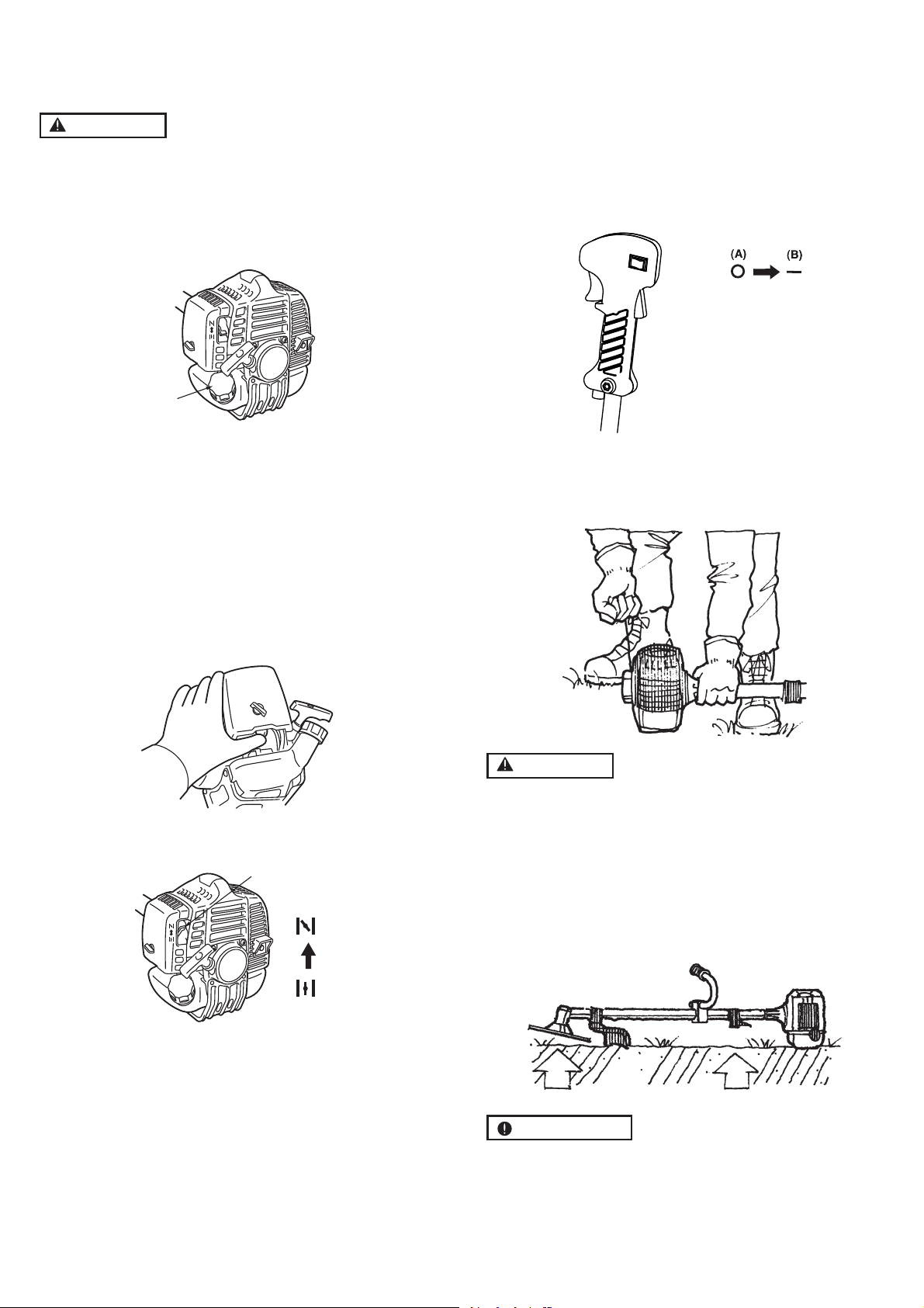
5. Set the stop switch to the “
-
” position. Set the throttle
trigger to the start position.
Place the unit on a flat, firm place.
Keep the cutting head clear of everything around it.
(A)Stop
(B)Run/start
GB 10
7. Operation
7. Move the choke lever downward to open the choke.
And restart engine.
(1) Choke lever (2) Close (3) Open
8. Allow the engine to warm up for a several minutes
before starting operation.
NOTE
1. When restarting the engine immediately after stop-
ping it, leave the choke open.
2. Overchoking can make the engine hard to start due
to excess fuel. When the engine failed to start after
several attempts, open the choke and repeat pulling
the rope, or remove the spark plug and dry it.
STOPPING ENGINE
1. Release the throttle lever and run the engine for half
a minute.
2. Shift the stop switch to the STOP position.
IMPORTANT
•Except for an emergency, avoid stopping the engine
while pulling the throttle lever.
IMPORTANT
•When it doesn’t stop at the stop switch, move the choke
level to the closed position.
(1) Choke lever
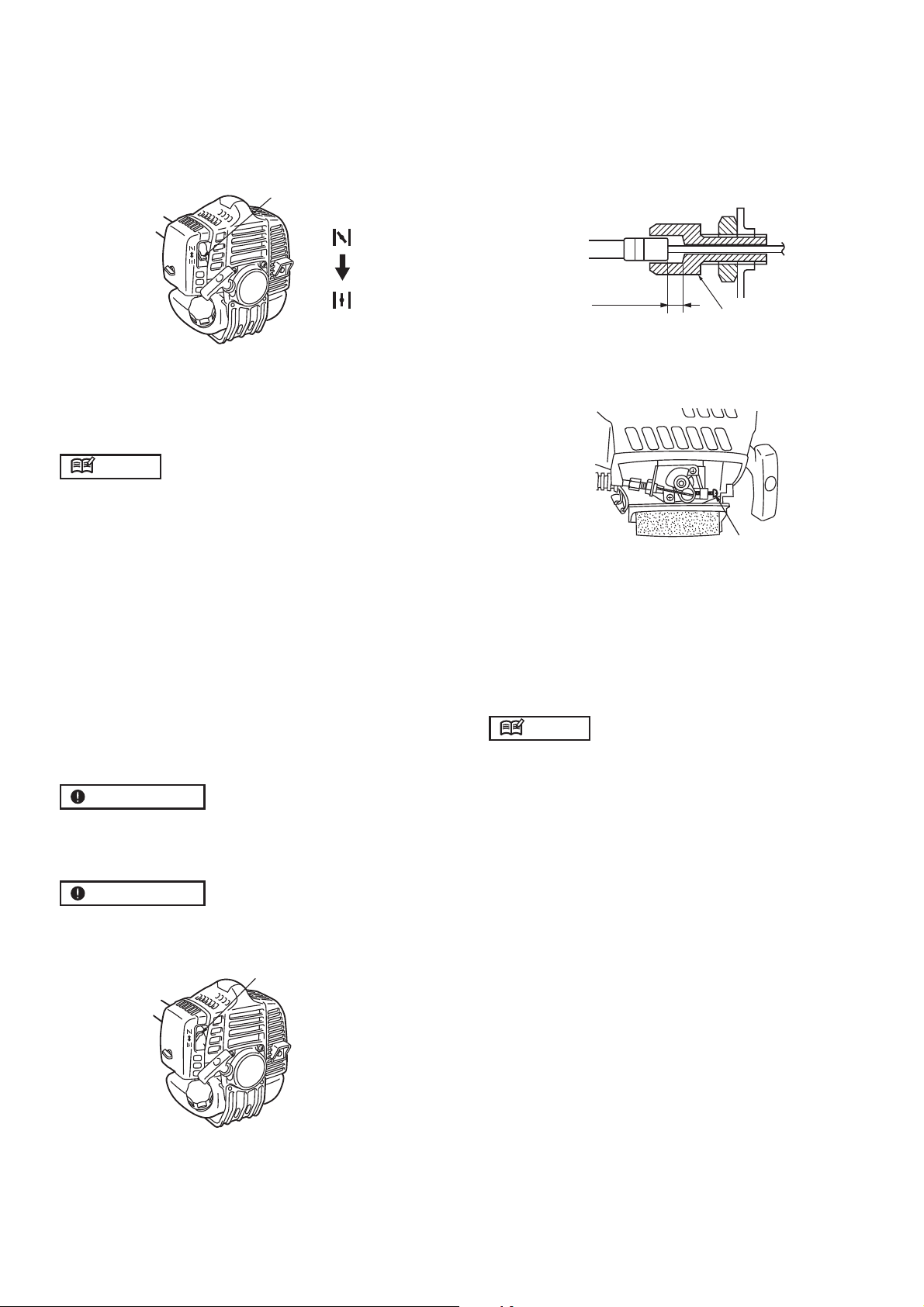
ADJUSTING THROTTLE CABLE
•The normal play is 1 or 2 mm when measured at the
carburetor side end. Readjust with the cable adjuster
as required.
(1)
(1) Cable adjuster
ADJUSTING IDLING SPEED
(1)
(1) Idle adjusting screw
1. When the engine tends to stop frequently at idling
mode, turn the adjusting screw clockwise.
2. When the cutting head keeps rotating after releasing
the trigger, turn the adjusting screw counter-clockwise.
NOTE
•W
arm up the engine before adjusting the idling speed.
1 ~ 2 mm
(1)
(2)
(3)
GB 11

7. Operation
G
B
CUTTING WORK (LINE HEAD USAGE)
WARNING
1. Always wear eye protection such as safety
goggles. Never lean over the rotating cutting head.
Rocks or other debris could be thrown into eyes
and face and cause serious personal injury.
2. Keep the cutting attachment guard in place at all
times when the unit is operated.
TRIMMING GRASS AND WEEDS
• Always remember that the TIP of the line does cut-
ting. You will achieve better results by not crowding
the line into the cutting area. Allow the unit to trim at
its own pace.
1. Hold the unit so the head is off the ground and is tilted
about 20 degrees toward the sweep direction.
2. You can avoid thrown debris by sweeping from your
left to the right.
3. Use a slow, deliberate action to cut heavy growth.
The rate of cutting motion will depend on the material
being cut. Heavy growth will require slower action than
will light growth.
4. Never swing the unit so hard as you are in danger of
losing your balance or control of the unit.
5. Try to control the cutting motion with the hip rather
than placing the full workload on the arm and hands.
6. Take precautions to avoid wire, grass and dead, dry,
long-stem weeds from wrapping around the head
shaft. Such materials can stall the head and cause
the clutch to slip, resulting in damage to the clutch
system if repeated frequently.
ADJUSTING THE LINE LENGTH
•Your brush cutters are equipped with a semi- auto
type nylon line head that allows the operator to ad-
vance the line without stopping the engine. When the
line becomes short, lightly tap the head on the ground
while running the engine at full throttle.
• Each time the head is bumped, the line advances
about 1 inch (25.4 mm). For better effect, tap the head
on bear ground or hard soil. Avoid bumping in thick,
7. Operation
CHOOSE THE BLADE
Choose a suitable recommended cutting attachment
according to the object to be cut.
Heavy
weeds
Light
weeds
Grass
Nylon
CUTTER
APPLICATION
TABLE
3 teeth blade Trimmer
GB 12

replace with a new one.
7. Operation
STARTING THE ENGINE
WARNING
The product is equipped with a centrifugal clutch
mechanism, so the cutting attachment begins to ro-
tate as soon as the engine is started by putting the
throttle into the start position. When starting the en-
gine, place the product onto the ground in a flat clear
area and hold it firmly in place to ensure that neither
the cutting part nor the throttle come into contact
with any obstacle when the engine starts.
CUTTING METHOD
a) Use the front left side cutting.
b) Guide the blade from your right to left with it tilted
slightly to your left.
c) When mowing a wide area, start working from your
left end to avoid interference of cut grass.
d) The blade may be seized by weeds if the engine
speed is too low, or the blade cuts too deep into
weeds. Adjust the engine speed and cutting depth
according to the condition of object.
WARNING
•If the grass or other object gets caught in the blade,
or if the unit starts to shake or vibrate, turn off the
engine and check the whole unit. Change the blade
if it has been damaged.
•Turn off the engine and make sure the blade has
completely stopped before checking the blade, and
removing any object got caught in.
OPERATION
1. Check the bolt to fasten the blade and be sure the
bolt has no fault, and no abrasion.
2. Be sure that the blade and the holder have been fas-
tened according to instruction and that the blade turns
smoothly without abnormal noise.
WARNING
•The rotating parts fastened incorrectly may cause
serious accident to the operator.
•Make sure that the blade is not bent, warped,
cracked, broken or damaged.
•If you find any error to the blade, discard it and
By using the shoulder strap, hang the unit on your right
side. Adjust the strap length so that the cutting head
may become parallel to the ground.
GB 13

7. Operation
WARNING
Make sure to use shoulder strap and cutting attach-
ment guard. If not, it is very dangerous when you slip
or lose your balance.
WARNING
CONTROLLING BLADE BOUNCE
Blade thrust can cause serious personal injury. Care-
fully study this section. It is important that you un-
derstand what causes blade thrust, how you can re-
duce the chance of blade thrust and how you can
remain in control of the unit if blade thrust does oc-
cur.
1. What causes blade thrust:
• blade thrust can occur when the moving blade
contacts an object that it cannot cut. This contact
causes the blade to stop for an instant and then
suddenly move or “bounce” away from the object
that was hit. The operator can lose control of the
unit and the blade can cause serious personal
injury to the operator or any person nearby if the
blade contacts any part of the body.
2. How you can reduce the chance of blade thrust:
a. Recognize that blade thrust can happen. By un-
derstanding and knowing about bounce, you can
help eliminate the element of surprise.
b. Cut fibrous weeds and grass only. Do not let the
blade contact materials it cannot cut such as hard,
woody vines and bushes or rocks, fences, metal,
etc.
c. Be extra prepared for bounce if you must cut where
you cannot see the blade making contact such as
in areas of dense growth.
d. Keep the blade sharp. A dull blade increases the
chance of bounce.
e. Avoid feeding the blade too rapidly. The blade can
bounce away from material being cut if the blade
is fed faster than its cutting capability.
f. Cut only from your right to your left.
g. Keep your path of advance clear of material that
has been cut and other debris.
3. How you can maintain the best control:
a. Keep a good, firm grip on the unit with both hands.
A firm grip can help neutralize bounce. Keep your
right and left hands completely around the respec-
tive handles.
b. Keep both feet spread apart in a comfortable
stance and yet braced for the possibility that the
unit could bounce. Do not overreach. Keep firm
footing and balance.
TRANSPORTING THE UNIT
• When you finish cutting in one location and wish to
continue work in another spot, turn off the engine, lift
up the unit and carry it, paying attention to the blade.
• Never forget to place the protective cover over the
blades.
• When transporting the unit over long distances, de-
tach the blade and fasten the unit by ropes.
GB 14

eplace if
8. Maintenance
WARNING
•Make sure that the engine has stopped and is cool
before performing any service to the machine. Con-
tact with moving cutting head or hot muffler may
result in a personal injury.
AIR FILTER
• The air filter, if clogged, will reduce the engine perfor-
mance. Check and clean the filter element in warm,
soapy water as required. Dry completely before in-
stalling. If the element is broken or shrunk, replace
with a new one.
(1)
(1) Air filter
FUEL FILTER
•When the engine runs short of fuel supply, check the
fuel cap and the fuel filter for blockage.
(1)
(1) Fuel filter
Every Every Every
25 50 100
System/components Procedure Before hours hours hours Note
use after after after
fuel leaks, fuel spillage wipe out ✔
fuel tank, air filter, fuel filter inspect/clean ✔✔ replace, if necessary
see adjusting replace carburetor
idle adjusting screw idling speed (p. 22) ✔if necessary
clean and readjust GAP: .025 in (0.6 ~ 0.7 mm)
spark plug plug gap ✔replace, if necessary
cylinder fins, intake air cooling vent
clean ✔
muffler, spark arrester, cylinder exhaust port
clean ✔
throttle trigger, stop switch check operation ✔
r
cutting parts something’s wrong ✔
transmission grease ✔
screws/nuts/bolts tighten/replace ✔✔not adjusting screws
cutting attachment guard make sure to attach ✔
ENGINE
SHAFT
GB 15

placement plug, use the correct type.
8. Maintenance
SPARK PLUG
•Starting failure and misfiring are often caused by a
fouled spark plug. Clean the spark plug and check
that the plug gap is in the correct range. For a re-
IMPORTANT
•Note that using any spark plug other than those des-
ignated may result in the engine failing to operate prop-
erly or in the engine becoming overheated and dam-
aged.
•To install the spark plug, first turn the plug until it is
finger tight, then tighten it a quarter turn more with a
socket wrench.
MUFFLER
WARNING
•Inspect periodically, the muffler for loose fasten-
ers, any damage or corrosion. If any sign of ex-
haust leakage is found, stop using the machine
and have it repaired immediately.
•Note that failing to do so may result in the engine
catching on fire.
0.6 ~ 0.9mm
TIGHTENING TORQUE: 9.8 ~ 11.8 N.m.
(1 ~ 1.2 kg.m.)
8. Maintenance
IMPORTANT
•If waste gets stuck and causes blockage around the
intake air cooling vent or between the cylinder fins, it
may cause the engine to overheat, and that in turn
may cause mechanical failure on the part of the
brushcutter.
(1)
(2)
(1) Cylinder
(2) Intake air cooling vent (back)
PROCEDURES TO BE PERFORMED AFTER
EVERY 100 HOURS OF USE
1. Remove the muffler, insert a screwdriver into the vent,
and wipe away any carbon buildup. Wipe away any
carbon buildup on the muffler exhaust vent and cylin-
der exhaust port at the same time.
2. Tighten all screws, bolts, and fittings.
3. Check to see if any oil or grease has worked its way
in between the clutch lining and drum, and if it has,
wipe it away using oil-free, lead-free gasoline.
GB 16

8.
Maintenance
REFILLING TRIMMING LINE
1. For replacement line, use a diameter of 2.4mm(.095in).
The spool is capable for a line upto 6m(20ft) on the
10cm(4”) head. Avoid using a larger line as it may cut
down the trimming performance.
WARNING
• For safety reasons, do not use metalreinforced line.
2. Pinch the slotted area on the both sides of the spool
housing to unhook the bottom cap.
3. Take out the spool and pull off the old line. Put one
end of new line through the spool holes and pull it
until the length is equal between each part of the line.
4. Wind up the line in the correct direction as indicated
on the spool.
5. Hook each end of the line in the slot on the edge of
the spool, and then put the ends through the eyelets
on the housing. Make sure that the spring and the
washers are in place.
6. While holding the spool against the housing, pull the
line ends to release them from the slot.
7. Line up the slot on the bottom cap with the hook on
the housing, press the cap against the housing until it
clicks.
8.
8.
Maintenance
BLADES
•When refilling the tank or resting, it is often a good
idea to use the time to oil the cutting blades.
• If a gap exists between the upper and lower blades,
follow the procedure below to adjust them so that they
fit more closely together.
(1) Upper blade (2) Lower blade
1. Loosen lock nut (A) as shown in the diagram.
2. Tighten screw (B) fully, and then turn one-third to one-
half of a rotation backward.
3. While holding onto the screw to keep it in position,
tighten the lock nut.
4. Check to make sure that the flat washer (C) is loose
enough so that it may be turned by pressing on it with
a finger.
Maintenance
ANGLE TRANSMISSION
•The reduction gears are lubricated by multipurpose,
lithium-based grease in the angle transmission. Sup-
ply new grease every 25 hours of use or more often
depending on the job condition.
• Remove the cutter holders before installing new
grease to arrange for old grease to exit.
GB 17

11. Troubleshooting guide
10. Disposal
9. Storage
Aged fuel is one of major causes of engine starting fail-
ure. Before storing the unit, empty the fuel tank and run
the engine until it uses all the fuel left in the fuel line and
the carburetor. Store the unit indoor taking necessary
measures for rust prevention.
Case 1. Starting failure
CHECK PROBABLE CAUSES ACTION
fuel tank →incorrect fuel →drain it and use correct fuel
fuel filter →fuel filter is clogged →clean
carburetor adjustment screw →out of normal range →adjust to normal range
sparking (no spark) →spark plug is fouled/wet →clean/dry
→plug gap is incorrect →correct (GAP: 0.6 ~ 0.7 mm)
spark plug →disconnected →retighten
Case 2. Engine starts but does not keep running/hard re-starting
CHECK PROBABLE CAUSES ACTION
fuel tank →incorrect fuel or staled fuel →drain it and use correct fuel
carburetor adjustment screw →out of normal range →adjust to normal range
muffler, cylinder (exhaust port) →carbon is built-up →wipe away
air cleaner →clogged with dust →wash
cylinder fin, fan cover →clogged with dust →clean
When disposing your machine, fuel or oil for the machine,
be sure to allow your local regulations.
GB 18
Table of contents
Languages:


