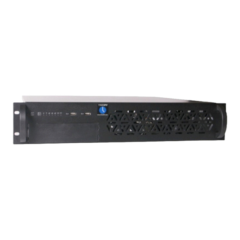
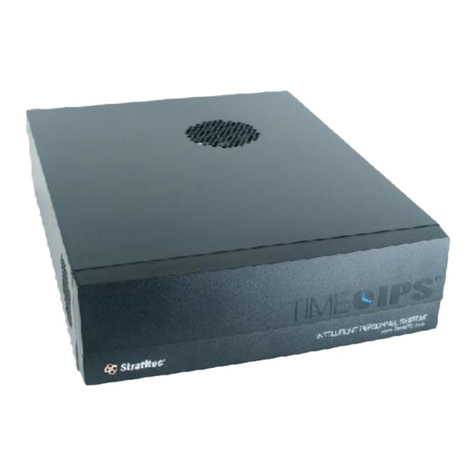
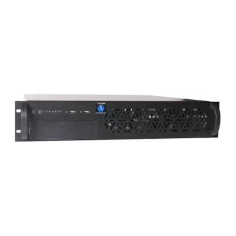
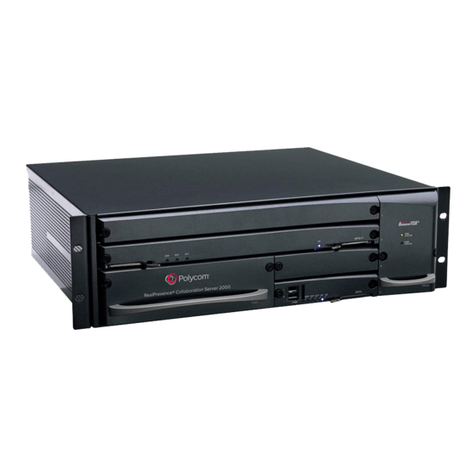
TimeIPS IPS200T User manual

IPS200T
TimeIPS Network Time Clock
Small-Business Server
Installation Guide

FCC Declaration of Conformity (DoC)
Compliance Information (according to FCC 2.1077)
(1) Product: IPS200T.
The above device complies with Part 15 of the CC Rules.
Operation is subject to the following conditions: (1) these devices may not cause harmful
interference, and (2) these devices must accept any interference received, including
interference that may cause undesired operation.
(2) The above device contains the following modular components authorized under their own
DoC.
Modular Component
Model Number
System Board
EPIA800
Power Supply
PSM200A-89
(3) The responsible party is TimeIPS, Inc. 3522 North Comotara, Wichita KS, 67226. Phone
316.264.1600
Notice to Users
The components in this system have been tested and found to comply with the limits for a
Class B digital device, pursuant to Part 15 of the CC Rules. These limits are designed to
provide reasonable protection against harmful interference in a residential installation. The
device generates, uses and can radiate radio frequency energy and, if not installed and used in
accordance with the instructions, may cause harmful interference to radio communications.
However, there is no guarantee that interference will not occur in a particular installation. If this
equipment does cause harmful interference to radio or television reception, which can be
determined by turning the equipment off and on, try to correct the interference by one or more
of the following measures:
•Reorient or relocate the receiving antenna.
•Increase the separation between the equipment and receiver.
•Connect the equipment into an outlet circuit other than the one to which the receiver is
connected.
•Consult the dealer or an experienced radio/TV technician for help.
These devices have been tested to comply with the limits for a Class B computing device,
pursuant to CC rules. In order to maintain compliance with CC regulations, shielded cables
must be used with the equipment if not connected directly to the system. Operation with
unshielded cables is likely to result in interference to radio and television reception.
CAU ION: Changes and modifications made to the device without the approval of the
manufacturer could void the user's authority to operate this device.
Page 2 http://support timeips com 316 264 1600 TimeIPS

able of Contents
Prepare and Plan 3
Layout and Installation Considerations 4
IPS200T Series Overview 5
Network Requirements 5
Ports and Connections 6
Mounting the TimeIPS System 7
Power-up and Determine IP Address 8
Network Connection Verification 9
Initial Login Using IP Address 10
Backups 11
Local Backups 11
Off-Site Backups 12
Network Troubleshooting 13
Network Settings in Windows 14
Additional Components 15
Technical Support 16
System Specifications 16
Prepare and Plan
TimeIPS installations consist of one "master" system and, optionally, one or more
additional "client" systems Initial configuration and periodic administration require
a computer with a network connection and a web browser Optional client systems
can be connected on a LAN (Local Area Network) or at remote locations connected
on a WAN (Wide Area Network) via secure VPN (Virtual Private Network) These
stations can be located at any door or entrance to your facility, or at any location
that is convenient for your employees to clock in and out If you only have one
TimeIPS station in your business, this will be the “master” station and will be used
by employees to clock-in and clock-out
We recommend a TimeIPS station at each employee entrance to your facility and/or
in your central break-room Each station will require an AC power outlet and a
connection to your local area network The master station can be connected to any
location on your network (wall plate jack, switch or hub)
Please examine the diagram on the next page to assist in planning your TimeIPS
installation Most installations will have the first station at the main employee
entrance Additional client stations can be added at any time to other entrances or
any location within your business
TimeIPS http://support timeips com 316 264 1600 Page 3

Layout and Installation Considerations
Page 4 http://support timeips com 316 264 1600 TimeIPS
LCD Display /
System Speaker
Employee
Identification
device
Power Source
(Wall outlet)
ecommended
UPS Power
Backup
(not included)
TimeIPS
station
Not e: Station can be
installed in the ceiling
or behind the wall.
Overall Installation Notes:
Installation of the TimeIPS system normally takes about an hour Our Technical Support Department
is available to assist if you have installation questions
TimeIPS systems can be clocks (client stations) or servers (masters) with additional network clock(s)
attached The number of attached clocks is limited by model If you are using the IPS200T as a
master, and need more than a single additional client, please call your TimeIPS sales representative
for assistance
The TimeIPS system should be installed in an indoor location, out of direct sunlight, meeting the
temperature requirements listed on the back cover of this guide
Possible Primary and Remote Facility Installation
E xisting E thernet
10/100 Network
E xisting E thernet
10/100 Network
Primary
Facility
Administratio n
and
Repo rting
(Passwo rd
Pro tected)
Side
Door
Front
Door
Back Door
Remot e
Facilit y
Typical Door Area Installation
TimeIPS master or
client stations
Any PC with a web
browser
Permanent network
connection
Permanent or
temporary network
connection

IPS200T Series Overview
TimeIPS systems can be used in either of the following applications:
•As a network Time Clock Station ("client"), connected to a TimeIPS Server
("master") system As a client, the system does not store data, as it is only
used to clock employees in and out
•As a TimeIPS server ("master") In this application, this system operates as
a total time and attendance solution to effectively manage time tracking
The IPS200T is designed to be used as a server ("master") for small businesses, or
as a Time Clock ("client") when a separate server is present on the network
Network Require ents
TimeIPS is an Ethernet TCP/IP appliance A standard RJ-45 Ethernet network cable
connects TimeIPS to your network The master/server station requires a Static IP
Additional client stations can be set to Static IP addresses, or can be dynamically
addressed with DHCP Client stations send a broadcast packet to look for a Master
on the same subnet Clients on different networks or subnets will need to be
manually configured (this is done by visiting http://<IP address of the
client>/quickset_ip php)
Ports Used By Ti eIPS
The following ports are used by TimeIPS on the Internet (if available) for the
reasons described below:
80 (HTTP) Required for update downloads
25 (SMTP) Recommended for email reports and messages
53 (DNS) Required for name resolution
123 (NTP) Recommended for time synchronization
443 (TimeIPS) Required for update and backup authorization
Please visit http://support timeips com for additional network and port information
Best practice: Configure all TimeIPS systems with Static IP addresss, provide an
always-on Internet connection (broadband) to all TimeIPS systems with all the
above outbound ports available
TimeIPS http://support timeips com 316 264 1600 Page 5

Ports and Connections
Page 6 http://support timeips com 316 264 1600 TimeIPS
USB Port s: Connect
to optional LCD Display
or USB input device
such as keypad,
proximity reader,
scanner or swipe reader
Power Swit ch: See
Power State table below.
Power State Action Effect
Powered OFF Press and release Power
Button
System will power on
Powered ON Press and HOLD Power
Button for 10 seconds
System will force emergency
power down This is not
recommended as it can cause data
loss Always shutdown from the
Administration interface option
Optional Large
Display
PS 2 Port : Connect to
optional PS/2 input
device, such as
keyboard, scanner or
swipe reader
Parallel Port : Connect
to optional LCD Display
Audio Out : Connect
to optional LCD Display
or to your own
amplified speakers
Net work Port : Connect to your
network with an J-45 Cable
Power Light : On when
the system is running.
Cooling Fan: Keep clear
for air circulation.
Serial Port : Connect to
optional LCD Display,
modem, power-backup UPS
Power Cord: Connect
to 110-240VAC.
Link and Act ivit y Light s:
Verify network connection

Mounting the Ti eIPS Syste
TimeIPS http://support timeips com 316 264 1600 Page 7
The Ti eIPS station can be ounted
vertically or horizontally on the wall.
The mounting brackets can be attached with
the mounting star visible, or hidden behind the
case
Visible/Hidden Mounts
Visible
Mount
Hidden
Mount
IMPORTANT: We recommend configuring the
system before mounting to the wall
(1) Choose Vertical or Horizontal orientation
and measure/mark mounting locations on the
wall
(2) Push the anchors into the wall until the
cutting blades penetrate the surface Using firm
forward pressure, rotate the anchor with a
Phillips head screwdriver until the collar sets
flush into the wall
(3) Insert the screws and tighten until screw
remains out about 1/4” from the wall surface
(4) Hang the TimeIPS station
Wall Mounting
and
Assemble Mark Locations
(E xi s ti ng wa l l ) (E xi s ti ng wa l l )
(E xi s ti ng
wa l l )
The station can be horizontally or
vertically mounted with the included
brackets.
Wall Mount Orientation

Power-up and Deter ine IP Address
Page 8 http://support timeips com 316 264 1600 TimeIPS
After the display and network cable are attached, power-on the station by plugging
in the power cord and pressing the Power Button if needed.
Step 1) Power On TimeIPS
Attention: The station may power on
immediately upon connecting the power cord
Note: If your display does not show text,
adjust the contrast knob until text appears
Cont ras t
knob
Powe r But t on
(Pre s s s ide labe le d “1”
brie f ly t o f orce powe r-on)
Powe r
light Volume knob
For aster station:
If the network is connected, the following messages will display in 1-2 minutes:
Write the IP address shown on the LCD display (Fig A/A1) below
http://_____._____._____._____
Fig. A
Welcome t o T imeIPS
Browse t o ht t p:
169.254.50.251
T o conf igure
Step 2) Network Connection Verification
If you DO NOT see the message above on your LCD display (Fig A), proceed to step 3
Th e actual IP address sh own on you r
LCD display will be different from t hi s
exam ple.
For client station:
If the client station is properly connected to your network, the following message
will appear on the display after it has found the master station on your network:
Fig. B
2008-01-01 12:00PM
T ype or scan your ID
Th is m essage in dicates th at t he
stat ion 's con figu rati on is
com plet e.
Note: If you see the message (Fig B) above and you only have one TimeIPS station, this is your
master station and it has already been configured It is now ready to accept clock-in/clock-out
events
If you DO NOT see the message above on your LCD display (Fig B), proceed to step 3
Fig. A1
Conf igure at ht t p:
169.254.50.251
Ent er or swipe badge
t o rest art net work

TimeIPS http://support timeips com 316 264 1600 Page 9
If no network connection is detected, Ti eIPS will display:
If no network connection is detected, check the network cable on the back of the
TimeIPS station Unplug and reconnect the network cable at both ends and/or try a
different network cable
For aster station:
If you're trying to connect a master station, write the IP address shown on the LCD
display (Fig C) in the space provided below
http://_____._____._____._____
Although the message on the LCD display (Fig C ) has not changed, you will proceed
with instructions on the next page to begin configuring the TimeIPS master station
For client station:
Unplug the power cord from the station, wait 1 minute and then plug it back in This
will allow the client station to search for a master station If a master station is located,
the TimeIPS LCD will display:
If the client station is still unsuccessful in locating the master station, please contact
technical support for further assistance
Note: After a client has connected to a Master at least once, you will see the following
display if the Master subsequently becomes unavailable
Fig. D
2008-01-01 12:00 PM
T ype or scan your ID
Fig. C
Welcome t o T imeIPS
Net work
disconnect ed
Please check cables
T ry 169.254.34.161
Step 3) Network Connection Verification (cont )
Th e actual IP address sh own on you r
LCD display will be different from t hi s
exam ple.
Note: The above message (Fig C) will remain on the LCD display after reconnecting the network cable
Th is m essage in dicates th at t he
stat ion 's con figu rati on is
com plet e.
Note: If you see the message (Fig D) above and you only have one TimeIPS station, this is your
master station and it has already been configured It is now ready to accept clock-in/clock-out events
Fig. E
IP: 169.254.34.161
MAST ER NOT FOUND
Press Ent er or swipe
badge t o t ry again
If you see this message (Fig E) it indicates that the client is no longer
able to reach the master station Pressing Enter or swiping a badge
will restart networking and the connection to the master If you
continue to get this message, check your network, master and/or
restart the client system

Initial Login Using IP Address
Page 10 http://support timeips com 316 264 1600 TimeIPS
Go to a PC on your
network with a web
browser
In your web browser,
enter the IP address
located on the TimeIPS
display to configure
TimeIPS
Beginning with the
screen shown here,
follow the instructions
that appear on each
screen
The setup process will
include creating the first
employee, who will
have access to all areas
of TimeIPS and who
will be able to designate
other employees as
administrators and/or
managers
Once you complete the
configuration, you can add and edit all settings and employees as needed
For assistance with further configuration and use of TimeIPS, please visit our
support web site at http://support timeips com If you do not find the information
you need there, call our Technical Support Department at 316 264 1600
IMPORTANT: During the configuration process, we recommend you update the
system and set a static IP address These two functions can also be done at a later
time under the Administration -> System Administration section in TimeIPS
Configuration Screen
Note: When you have successfully connected to TimeIPS from your
PC, the screen on your PC should look like the screen above After
reading the information at the bottom of this page, you will be ready to
proceed with the guided setup process
Not e : The actu al IP
address shown on you r
LCD display will be
different from t hi s
exam ple.

Backups
TimeIPS http://support timeips com 316 264 1600 Page 11
FOR YOUR PROTECTION, SECURITY AND BUSINESS OPERATING
EFFICIENCY, WE STRONGLY RECOMMEND REGULAR AND FREQUENT
DATA BACKUP
TimeIPS will store important personnel management data and it's critical for this
data to be backed up regularly We recommend daily backups
TimeIPS will allow you to make manual backups at any time If you would like the
enhanced security and protection of automatic off-site backups, we provide an off-
site backup service that allows you to send backups automatically to our servers
and/or to your own servers with FTP or SFTP each day
Local Backups
TimeIPS can generate local backups at any time You may choose to save these as
an archive on your local machine, or have them emailed to a specified email
address We recommend you use our off-site backup option in addition to local
backups for the highest data security
If you only choose to email your backup files to a chosen email address, you must
monitor the backup file size to ensure your email server and inbox have sufficient
space allocated for the size of the TimeIPS backup data To access local backups,
click on “Backups” in the “System Administration” section of the
“Administration” Menu
Note: The data stored in TimeIPS (and the resulting size of backups) grows as a result of
additional clock events, edits and payroll calculations added each day
“Administration” > “System Administration” > “Backups"

Off-Site Backups
Page 12 http://support timeips com 316 264 1600 TimeIPS
The best way to protect the TimeIPS data is to use an automatic, off-site backup system A
loss of just a few days of data can take hours or days of work to re-enter and re-create
The TimeIPS off-site backup service is designed for businesses that are looking for password-
protected, automatic, off-site backups at an affordable price Utilizing our off-site backup
service will allow a TimeIPS master system to be rebuilt using the data from the last available
backup file on our secure servers in the unlikely event of system malfunction, data corruption
or loss A backup will get your business back up and running as quickly as possible
To use the TimeIPS off-site backup service, you must have a backup account Use our
“Account Management” page to sign up for your backup account, check your backup account
status, or upgrade your backup account You may access this page by clicking the link
“TimeIPS Off-site Backup Account Management” located in the “Off-site Backup” section of
the “Backups” page, and follow the instructions on this page The “Backups” page is
accessible from the “System Administration” section of the “Administration” menu
A security password is used to encrypt off-site backups This password should be chosen
carefully and MUST NOT BE LOST OR FORGOTTEN Recovery of a lost or forgotten
security password requires sending the TimeIPS station to our service department and paying
a service fee In the unlikely event that the TimeIPS station is lost in a natural disaster, fire, is
destroyed, completely corrupted, or suffers total failure, you must have your security
password to restore your data from the off-site backup Contact our Technical Support
Department if you have any questions
I portant: An Internet connection is required to use off-site backups
“Administration” > “System Administration” > “Backups"

Network Troubleshooting
TimeIPS http://support timeips com 316 264 1600 Page 13
If you have trouble accessing TimeIPS from a PC, you may be having network related issues Follow this
checklist to verify your network settings and connectivity
✔If the System’s “network activity indicator” lights (shown on page 8) are not lit, then check all wires,
hubs and switches to verify the physical connections If cables are disconnected, you will need to
reconnect these for proper network functionality After reconnecting network cables, you may need to
restart your PCs and/or TimeIPS station(s) to reestablish the network connection
✔Check the power light to verify that the TimeIPS master station is powered on and that the LCD
display indicates that it is ready for use (see page 6)
✔Enter the TimeIPS IP address (the IP address can be located on the system configuration page) into a
web browser on another PC on your network (see page 10) If you see the TimeIPS setup page, then
your network and TimeIPS are working properly
The IP address assigned to your desktop PC must be reachable by the TimeIPS IP address as shown on the
TimeIPS display For example, if the address on the TimeIPS display begins with 169 254 ___ ___, then
your PC must also have a 169 254 ___ ___ IP address with a “netmask” of 255 255 0 0 in order to connect
to the TimeIPS station (see System Configuration page) The last two numbers you choose should be a
number between 1 and 254 If you need to change your PC's IP Address to reach the TimeIPS master
station, follow the instructions for your PC's operating system
Setting or changing your PC's IP Address:
If you are not able to connect, you may need to change your PC's IP address to connect to the TimeIPS
Master station When making changes to your PC's Network settings, be sure to record any previous
settings, so that you may restore them after you have set your TimeIPS Master station to the correct IP
Address for your network
To change your IP address in Windows, follow the instructions on the following page (page 14) For help
changing your IP Address from any other Operating System, please use an Internet search engine to look
for "IP settings" and your operating system name and version
Note: After initial configuration and guided setup is complete, the System Administrator can shut down
or restart the master station from the “System Settings” page accessible from the “System
Administration” section of the “Administration” menu Wait for the power indicator light to turn off
before unplugging the power cord
Obtains an address automatically? (DHCP) [ Yes / No ]
If set, what is the IP Address of your PC? [ _____ _____ _____ _____ ]
If set, what is the Subnet of your PC? [ _____ _____ _____ _____ ]

Network Settings in Windows
Page 14 http://support timeips com 316 264 1600 TimeIPS
To configure the IP address of your PC
or notebook running the Windows XP or
Windows 2000 operating system:
1 Open Windows “Start” menu
2 Open “Control Panel”
3 Classic view: Open “Network
Connections”
Category view: Select “Network and
Internet Connections,” and then
“Network Connections”
4 Double-click on your active “LAN or
Internet connection”
5 Click “Properties”
Windows XP/2000
"Start" Menu
“Control Panel”
Classic view
“Control Panel” Category view
“Control Panel” Category view
“Network
Connections”
“TCP/IP Properties”
“Connection
Properties”
To configure the IP address of your PC
or notebook running the Windows
95/98/98se or Windows ME (Windows
Millennium) operating system:
1 Open Windows “Start” menu
2 Open “Control Panel”
3 Open “Network”
4 Select the TCP/IP protocol (NOT
dial-up adapter) and Click
“Properties”
Windows 95/98/ME
"Start" Menu
“Control Panel”
“Network”
“TCP/IP Properties”

Additional Co ponents
TimeIPS http://support timeips com 316 264 1600 Page 15
Keypad
The keypad can be used to clock in/out with a PIN number,
check status, enter numeric clock notes, provide job tracking
numbers, and perform system maintenance codes
Barcode Reader
The barcode badge reader can be used to clock in/out with bar-
code based employee badges and/or to scan job codes
Proxi ity Badge Reader
The proximity badge reader allows
employees to clock in/out by simply bringing their
badge close to the reader Offers convenience and
higher-security employee identification
Additional Proxi ity Badges
For additional employees, purchase badges in packs
Large Display
The large display can provide additional information
including an optional list of “Who's Clocked-in” at your
facility (on supported TimeIPS models) Use a VGA
compatible monitor or flat screen supporting 1024x768
Magnetic Swipe Badge Reader
The magnetic swipe badge reader allows employees to
clock in/out quickly by simply swiping their badge
Additional Magnetic Swipe Badges
For additional employees, purchase badges in packs,
or in bulk quantities for large deployments

Technical Support
Technical Support Resources:
1 Our support web site at http://support timeips com offers extensive
resources including documentation and our knowledge-base Please check
our support web site first, as it provides complete answers and instructions
on almost everything In the "Knowledge Base Search:" box, enter a few
words describing your question For example, if you have a question on
payroll, enter "payroll" and browse the articles listed Our knowledge-base
works so well that, if you call us, we're likely to search it ourselves to find
the answer you need
2 If you have a question not answered on our support site, you can call or
email us A period of limited email/phone support is included with your
system A serial number or registration number is required for this service
Additional support can be purchased by calling TimeIPS, or by visiting our
web site at http://secure timeips com
3 If you have a simple question, or need direction on how to use our support
resources, feel free to email us at support@timeips com If your question
is quick, we'll be happy to help If it's not, we'll let you know that you
need to purchase additional support
Support website http://support.ti eips.co
Support e- ail support@ti eips.co
Support phone nu ber 316.264.1600
This manual is copyright 2008 TimeIPS, Inc TimeIPS and the TimeIPS logos are registered trademarks of
TimeIPS, Inc All other trademarks are the property of their respective owners
Thank you for reading this manual carefully If you noticed errors, have any suggestions or found
typographical problems, we want to know! Please send an email with the version code below and your
feedback to documentation@timeips com We appreciate your time Version: IPS200T_1 0 0 080130
Page 16 http://support timeips com 316 264 1600 TimeIPS
System Specifications:
Approximate dimensions:
11in (28cm ) x 1.7in (4.3cm) x 7in (17.9cm)
Approximate weight:
5.3lb (~2.4kg)
Power: 100-240VAC, 25W (typical)
Operating environment:
Clean and dust free,
Proper air circulation around unit,
3in (7.62cm) ventilation clearance,
32° - 90°F (0° - 33°C) non-condensing
System Administration Requirements:
PC with modern OS.
(Linux™, MacOS™ or Windows™)
A network port and an up-to-date
version of Firefox™ IE™ web browser.
Network Requirement:
10/100Base-T Ethernet,
Internet connection required for email
notifications, time synchronization,
updates and off-site backups
Table of contents
Other TimeIPS Server manuals
