Tippmann BOSS User manual

TIPPMANN
HAND STITCHER
OPERATOR'S MANUAL
THE TIPPMANN
"
BOSS
"
INDUSTRIAL PRODUCTS, INC.
BACK COVER
Rev: 06-06-07

WARNING
READ THROUGH THIS MANUAL THOROUGHLY AND BECOME FAMILIAR
WITH THE TIPPMANN “BOSS” PARTS, OPERATION, AND SAFETY
PRECAUTIONS BEFORE YOU ATTEMPT TO OPERATE THIS MACHINE.
CONGRATULATIONS on your purchase of the Tippmann "BOSS"
hand stitcher sewing machine
3518 Adams Center Road, Fort Wayne, IN 46806
260/441-9603 • 866/286-8046 • FAX: 260/441-8264
INTERNET: www.tippmannindustrial.com
1
TIPPMANN
INDUSTRIAL PRODUCTS, INC.
INDEX
Index: Table of Contents ..................................................................................... 1
Standard Equipment ........................................................................................... 1
Warning / Liability Statement .............................................................................. 2
Safety Is Your Responsibility ............................................................................. 2
General Description ............................................................................................ 2
Specifications ...................................................................................................... 2
Setup Instructions ............................................................................................... 3
Installing the Needle............................................................................................ 4
Installing Bobbin In Bobbin Shuttle ..................................................................... 5
Threading the Machine ....................................................................................... 6
Threading The Needle ........................................................................................ 7
Drawing Bobbin Thread Up Through Needle Plate ..........................................7/8
How To Sew........................................................................................................ 8
Presser Foot Adjustment..................................................................................... 9
Stitch Length Adjustment .................................................................................. 10
Schematic View Detailed Illustration with part numbers .............................. 10/11
Adjusting the Stitch (Needle & Bobbin Thread Tension)................................... 12
Recommended Thread & Needle Specifications .............................................. 13
Trouble Shooting.......................................................................................... 14/15
Gear Rack Replacement & Timing Instructions ........................................... 16/17
Cleaning and Lubricating The Machine............................................................. 18
Warranty & Repair............................................................................................. 19
Additional Tippmann Products & Accessories ............................................. 20-22
• 2 Bobbins
• Assortment of 10 Needles*
• Standard Presser Foot*
• Shuttle
• Allen Wrench Set
• Thread Stand
• Bobbin Winder - (Attaches to electric drill)
• Needle Plate
*See Additional Products & Accessories pages for options.
STANDARD EQUIPMENT

2
1. To Secure machine to existing work bench use three (3) 3/8"
bolts or lag screws of suitable length.
2. Attach the Stitching Handle to
the BOSS. Slide the Stitching
Handle onto the shaft & secure the
handle in position with bolt (HS
100-3).
3. Attach the Thread Stand.
1) Insert the Thread Stand Post
into the center of the thread stand
base and secure with nut.
2) Insert the bolt through the
thread guide and thread stand
plate and carefully start it into the
provided hole on the top of the
sewing machine. Position the
thread guide to allow the thread
to feed into thread guide B
unobstructed and tighten the bolt
to secure.
CAUTION: Always keep your free
hand clear of presser foot and
needle foot during operation -
including during the following
tests. MOUNTING
HOLES
(3)
NEEDLE
FOOT
PRESSER
FOOT
THREAD
STAND
PLATE
THREAD
STAND
POST
THREAD
GUIDE
THREAD
GUIDE
"B"
PRESSER
FOOT
LIFTING
HANDLE
STITCH
HANDLE
• To Check* the Presser Foot Lift:
(*Always be sure the presser foot path
is clear of hands, tools etc.)
With machine secured to a stable work
bench, lift the Presser Foot by
squeezing the Presser Foot Lifting Handle.
The Presser Foot should lift approximately 7/8 inch.
• To Check* the Stitching Handle:
(*Always be sure needle foot path is clear of hands, tools etc.)
Withmachine securedto astable workbench, Cyclethe NeedleFoot:
(by pulling the Stitch Handle completely down and then return it
completely to the upright position).
• To Insert Needle -See page 4
•To Thread Machine -Seepage 6
HS 100-3
GUIDE
PIN
HOLE
3
THREAD
GUIDE
Bolt
This Tippmann "BOSS®" hand stitcher sewing machine is surrendered by
Tippmann Industrial Products, Inc., with the understanding that the purchaser
assumes all liability resulting from unsafe operation. Tippmann Industrial
Products, Inc., shall not be liable for personal injury resulting from the use of
this machine under any circumstances.
All information in this manual is subject to change without notice and in no way
represents a commitment on the part of Tippmann Industrial Products, Inc. We
reserve the right to make changes and improvements to products without
incurring any obligation to incorporate such improvements in products previously
sold.
The ownership of this machine places upon you the total responsibility of its
safe operation. You must observe the same safety precautions as you would any
piece of equipment to assure the safety of not only yourself but everyone around
you.
Outlinedhere are somegeneral precautions tobe aware of: theoperator should at
alltimes use commonsense when usingthis machine and be sure others who may
operate are also familiarized, responsible and safety conscious. Do not attempt to
operatethis machine untilyou have readand are familiarwith this manual. Common
sense includes reading, reviewing and understanding these written instructions
before operating or setting up this machine including but not limited to:
• Before changing needles.
• Before threading needles.
• Before changing bobbin.
• Before disassembly of machine. • Before moving machine.
• Do not attempt to operate this machine until it is securely fastened to a sturdy
work surface.
• Do not operate this machine when parts have been removed as damage to the
machine and/or injury to operator may result.
• Keep hands clear of presser foot and needle at all times.
Make .........................................................................................TIPPMANN
Model ............................................................................................"BOSS2"
Type Feed.............................................Needle Feed/Lower Needle Guide
Type Stitch .................................................................................Lock Stitch
Type Bed........................................................................... 3 " Cylinder Bed
Throat Depth .........................................................................................6.5"
Stitch Cycle Rate.........Variable - 1 to 100 Stitches (1" to 15"+ per minute)
Presser Foot Clearance ..................................................................7/8 inch
Maximum Sewable Thickness ........................................................3/4 inch
Needle System...............................................................794 Series & 7 x 3
Thread Sizes................................................................................ 69 to 415
Stitch Length Adjuster.......................................... 4 per inch to 16 per inch
Machine Weight ......................................................................... 25 Pounds
The Tippmann "BOSS" hand stitcher sewing machine is a needle-feed, lock-
stitch machine. The "BOSS" is designed and built to achieve precision quality
stitching, extreme durability of the machine itself and maximum owner
satisfaction for many years.SPECIFICATIONS
GENERAL DESCRIPTION
SAFETY IS YOUR RESPONSIBILITY!
WARNING / LIABILITY STATEMENT SETUP INSTRUCTIONS

4
• Lower the needle foot
by pulling the stitch
handle until the
needle set screw
is visible.
• Loosen needle set
screw with furnished
allen wrench to allow
needle to be inserted
into needle bar hole.
• Insert needle
shank first,
fully into
needle bar
hole with
scarf spot
facing the
needle
set screw.
• With needle fully
inserted and
scarf spot facing
the needle set screw,
tighten set screw
firmly with the
allen wrench.
NEEDLE
FOOT
NEEDLE
BAR
NEEDLE BAR HOLE
NEEDLE
SHANK
Needle
Scarf
Spot
Towards
Set Screw
NEEDLE
SET SCREW
ALLEN
WRENCH
ACCESS
POINT
5
• Locate the bobbin shuttle in the end
of the cylinder bed. Press the shuttle
release latch to release the bobbin
cylinder (point A).
• Remove the empty bobbin spool
and wind with thread.
Do not fill bobbin to the point that is
has to be forced into bobbin shuttle!
• Insert wound bobbin with
6 - 8 inches of thread kept out
counterclockwise as pictured.
• Hold bobbin in place to keep it from
turning. Now pull thread down the
tension spring slit (B) until thread
reaches thread slot in the shuttle.
• Secure shuttle by snapping the bobbin
cylinder back into place. There should
be 6 - 8 inches of thread hanging out
of the Bobbin Shuttle at the end of the
cylinder bed at this point.
(Bobbin Thread Tension Adjustment
Instructions on page 12)
A
Bobbin Shuttle
INSTALLING THE NEEDLE INSTALLING BOBBIN IN BOBBIN SHUTTLE

6
Place selected thread on thread
stand. Lead thread through all
threading points as shown. Thread
Guide
Thread
Thread
Stand
Thread
Guide
Thread
Take-Up
Arm
Primary
Tensioner
Wheel
Secondary
Tensioner
Wheel
Thread
Guide Guide
Post Guide
Post
1. Loop thread over thread stand - Thread Guide .
2. Pass thread through 2 holes in Thread Guide .
3. Weave thread around guide post as shown above.
4. Loop the thread counterclockwise once around back side
of Secondary Tensioner Wheel as shown above.
NOTE: Wheel shown from top view.
5. Loop thread clockwise once around the Primary Tensioner
wheel as shown above. NOTE: Wheel shown from top view.
6. Pass thread through guide post as shown above.
7. Pass thread thread through Take-up Arm as shown above.
(NOTE: The primary tensioner wheel should rotate clockwise as
thread is drawn through the thread take-up arm).
8. Continue thread through thread guide asshown aboveand
down edge of machine through needle foot as shown above.
Youarenowreadytothread the needle. (Above Needle — shown
threaded.)
7
• Pass the thread down through needle
foot then thread through the needle eye
from left to right as shown in illustration.
• Pull about 6 - 8 inches of thread
through the eye of the needle.
(Continued on page 8)
THREADING THE MACHINE THREADING THE NEEDLE
DRAWING BOBBIN THREAD UP THROUGH NEEDLE PLATE
STEP 2: Looping bobbin and needle
threads.
• Hold the needle thread lightly to the
rear as shown and cycle the handle
(pull down & up completely one time
without releasing the end of the needle
thread. This action loops the bobbin
and needle threads together inside the
cylinder bed.
If it does not loop, be sure to hold the
thread gently to the rear as outlined in
Step 1 and try again. NOTE: Be
careful not to pull the thread tightly or
the loop will not form and the shuttle
will not be able to pass through the
loop as required.
STEP 1:
• Place the thread under the presser
foot and hold very lightly to the back .

How do I start and finish locking a stitch?
• You will want to make sure that your sewing machine is on a
sturdy work surface before starting any set up or maintenance
of ........................... your machine.
• Start on your material about ¼” from where you would normally
start.
• Sew to where you would normally start, then turn your material
around and sew back through the previous holes and continue on.
• When you are to the end of your stichline, lift your presser foot
and move your material back, to line up your needle with the
previous hole and then repeat.
• If you are in need of additional assistance feel free to call us Toll
Free: 866-286-8046 8
Adjust the stitch length with the Stitch
Length Adjustor.
• For a larger stitch.
Turn the Stitch Length Adjustor clockwise .
• For a smaller stitch.
Turn the Stitch Length Adjustor
counterclockwise .
• When the material thickness is
increased, the stitch length
shortens.
Length of stitch is proportional to thickness
of material. To maintain an even stitch
length adjust accordingly. Turn the stitch
length adjustor approximately 1/4 turn
clockwise for 1/4 inch climb (increased
thickness). 9
The Presser Foot Adjustor adjusts the Presser Foot Pressure.
A properly adjusted Presser Foot will
advance the material without slipping.
Stitch
Length
Adjustor
Presser Foot
Adjustor
Stitch
Length
Adjustor
Presser
Foot
Adjustor
• Use a piece of the material to be sewn.
• Insert the sample material under the
Presser Foot and sew a couple stitches.
•Observe thetest materialduringstitching.
- If the material is not advanced by the
Presser Foot, the pressure needs to be
increased.
- If the presser foot leaves a deep
impression on the material, the pressure
needs to be decreased.
To determine the proper pressure for
the material to be sewn, perform the
following test.
To increase the Pressure.
• Turn the Presser Foot Adjustor clockwise . Re-test as before and
adjustuntilthematerialisadvancedbythePresserFootwithoutslipping.
To decrease the Pressure.
• Turn the Presser Foot Adjustor counterclockwise . Re-test and
adjust until the material is advanced by the Presser Foot without
leaving a deep impression.
STEP 4: Aligning threads to sew.
STEP 3: Drawing up the bobbin thread.
• Lift the presser foot and pull the needle
thread up. The bobbin thread will
come up with it through the needle
plate.
• Align both threads under the presser
foot to the back as shown.
• You are now ready to sew. NOTE: It is
necessary to hold thread ends to begin
stitching.
DRAWING BOBBIN THREAD UP THROUGH NEEDLE PLATE
HOW TO SEW:
PRESSER FOOT ADJUSTMENT
STITCH LENGTH ADJUSTMENT

11
10

TENSION
ADJUSTOR
SCREW
(FLATHEAD)
12
NEEDLE THREAD
A PERFECTLY LOCKED STITCH
results with upper and lower
tensions balanced so that needle
and bobbin threads are drawn into
material equally.
NEEDLE THREAD
BOBBIN THREAD
NEEDLETHREADISNOTBEING
DRAWN INTO MATERIAL
Needle thread tension may be to
tight.
• Lower needle thread tension by
adjusting the Primary Tensioner.
- Turn the Primary Tensioner
adjusting nut counterclockwise
to lesson the needle thread tension.
NEEDLE THREAD IS BEING
DRAWN THROUGH MATERIAL
Needle thread tension may be too
loose.
•Tighten needlethread tension by
adjusting the Primary Tensioner.
- Turn the Primary Tensioner
adjusting nut clockwise to
increasethe needlethread tension.
NEEDLE THREAD
BOBBIN THREAD BOBBIN THREAD
BOBBIN THREAD IS NOT
BEING DRAWN INTO FABRIC
Bobbin thread tension may be
too tight.
• First loosen locking screw.
• Loosen bobbin thread tension by
turningbobbintensionadjustorscrew
counterclockwise.
• Tighten locking screw to hold
adjustment.
NEEDLE THREAD
BOBBIN THREAD
BOBBIN THREAD IS BEING
DRAWN THROUGH FABRIC
Bobbin thread tension may be
too loose.
• First loosen locking screw.
•Tightenbobbin threadtensionby
turning bobbin tension adjustor
screw clockwise.
• Tighten locking screw to
hold adjustment.
Material
BOBBIN THREAD
NEEDLE THREAD
Material
Material
LOCKING
SCREW
(X-HEAD)
(Recommend
7 X 3 & 794s Series Needles)
After selecting desired thread
and needle point, place thread
through eye of needle and hold
thread as pictured with hands
about 10 inches apart. If needle does not
slide freely down
the thread —
select larger needle.
Thread ROUND POINT CHISEL POINT
Size 7 x 3 Needle ................ Part # 794s Serv 1Needle . Part #
69 7 X 3 110 .................. 7x3110 -.....................................-
99 7 X 3 110 .................. 7x3110 -.....................................-
138 7 X 3 130 .................. 7x3110 -.....................................-
207 7 X 3 160 .................. 7x3110 794s Serv 1 160......SM 53-9
7 X 3 180 .................. 7x3110 794s Serv 1 180......SM 53-7
7 X 3 200 .................. 7x3110 794s Serv 1 200......SM 53-4
346 7 X 3 230 .................. 7x3110 794s Serv 1 230......SM 53-5
415 7 X 3 230 .................. 7x3110 794s Serv 1 230......SM 53-5
Recommended Thread and Needles for Tippmann Boss
277
NOTE: Round Point Needles Are For General Purpose - Including Leather.
Chisel Point Needles Are Generally Used For Leather.
13
RELATIVE SIZES OF NEEDLES & THREAD
THREAD SPECIFICATIONS
ADJUSTING THE STITCH
NEEDLE THREAD TENSION — ADJUSTMENTS
BOBBIN THREAD TENSION — ADJUSTMENTS

14
TROUBLE SHOOTING YOUR BOSS HAND STITCHER:
The following instructions are illustrated in the trouble shooting section of your
instructional and trouble shooting video, which was provided with your machine.
Refer to the machine schematic on pages11 and 12 as you review these trouble
shooting tips.
BEFOREDOING ANY MAINTENANCE OR ADJUSTING OF YOUR BOSS HAND
STITCHER, MAKE SURE THAT YOUR MACHINE IS MOUNTED ON A STURDY
WORK SURFACE.
1. I SEEM TO BE MISSING STITCHES. If you are missing stitches:
• Check to make sure that you have the correct needle size for the size thread
which you are using.
• If you have found that your needle size and thread are correct, try turning your
needle to the left or to the right a couple of degrees, using the allen wrench
provided in your accessory kit.
• If you are still missing stitches, you will want to adjust your rack stop 1 to 2 full
turns. The rack stop is located in the lower left hand corner behind cover.
TO ADJUST THE RACK STOP (AR-100-4), DO THE FOLLOWING:
1. Remove back cover
2. Loosen Hex Nut
3. Turn your bolt 1 to 2 full turns
4. Replace back cover
2. MY THREAD IS BINDING OR JAMMING. If your thread is binding or jamming,
the first thing you should do is check your primary and secondary tensions. Refer
to your schematic to locate your primary and secondary tensions.
TO ADJUST THE TENSIONS, DO THE FOLLOWING:
1) Back the nut off until it is no longer touching the spring.
2) Secondary tensions should be set at 2 full turns from the time the nut touches
the spring.
3) Primary tensions should be set at 1&1/2 turns from the time the nut touches
the spring.
3. I HAVE CHECKED MY TENSION, BUT MY THREAD IS STILL JAMMING
AND DOUBLE LOOPING, WHAT SHOULD I DO?
• Make certain that the lever thread take up (AR-12) is coming up all of the way.
• Take the thread out of the needle.
• Hold the stitching handle all of the way forward, while holding your hand on the
stitching handle.
• Apply pressure on the handle and with your other hand, try to move the lever
thread take up, up and down.
• If the lever thread take up (AR-12) moves up and down, while applying pressure
to the handle, you will want to remove the back cover and follow these steps.
1) Look for the shaft needle bar (AR-44) . You will notice there is a bracket on
the shaft itself. You will find the ARM bracket (CAR-11) - thread take up,
attached to the roller.
2) When pressure is being applied to the handle, the roller should be touching
the bottom of the thread take up arm (AR-12).
3) If the roller is not touching the bottom of the thread take up arm (AR-12) ,
loosen the bolt which goes through the thread take up bracket 2 to 3 turns and
rotate until it touches.
4) You will thenwanttoretightenthe boltwhich goes throughthethread takeuparm
bracket (CAR-11).
(CONTINUED ON PAGE 15) 15
You may have to experiment by turning your adjustment a couple of times.
• Make sure your bobbin tension is very loose.
• If you are still having problems, you should go to a larger needle. You will want
to try 1 to 2 sizes larger than the needle you are currently using.
• You will then want to try wrapping the thread another time on the secondary and
primary tensioners.
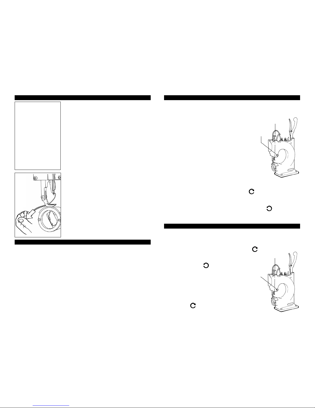
5. MY TIMING MAY BE OFF, WHAT SHOULD I DO TO REMEDY THIS?
• Make sure the tip of the long ear of the shuttle driver (AR-42) is right at or right
before 12 o’clock when the stitching handle is all of the way forward.
6. MY THREAD IS FRAYING, HOW DO I STOP IT FROM FRAYING?
• Check your thread and make sure that you are using a nylon or polyester thread.
• If you are using a nylon or polyester thread and it is fraying, make sure that it is
not frayed off of the spool. If the thread is frayed off of the spool, call the retailer
where you purchased the thread and let them know.
• If your thread is not frayed off of the spool, you may need to make a minor
adjustment on your machine. You will want to call Tippmann’s toll free service
line and speak to a technician.
7. I AM MISSING STITCHES WHILE SEWING SHEEPSKIN, WHAT SHOULD I DO?
• The easiest way to fix this problem is to put a piece of duct tape over the needle
plate (AR-41), this will to keep the wool out of the cover area.
• You will then want to cut a slot into the duct tape, directly into the slot of the
needle plate.
8. HOW DO I INSTALL MY NEEDLE FOOT?
1) Remove needle from needle bar.
2) Remove presser foot (SM-16-1)
3) Remove needle plate (AR-41)
4) Remove the retainer ring screws (AR-160-5) and the retainer ring (AR-02). You
will notice the shuttle (SM-59) comes out with the retainer ring.
5) Remove the front cover screws (SM-100-3) and the front cover (AR-30).
6) Pull the stitching handle (HS-31) down
7) Remove the 5/64 set screw, located above the slot window in the needle bar.
8) Hold the needle foot (AR-20) while raising the stitching handle, then remove
the needle foot (AR-20), along with the spring.
9) You will replace the spring (AR-52) and the new needle foot (AR-20).
10) Place your small standard screwdriver in the slotted window on top of the
spring (AR-52) and push the needle foot (AR-20) up, then insert the 5/64 set screw.
11) The final step is to replace all other parts.
1. Replace front cover (AR-30).
2.Replace shuttle (SM-59) and retainer ring 9 (AR-02) by:
- Place shuttle (SM-59) into the retainer ring (AR-02).
- Put retainer ring (AR-02) back on.
3. Replace needle plate (AR-41). Note, do not lock down all of the way, leave it
a bit loose.
4. Replace presser foot (SM-16-1).
5. Replace needle.
6.Finally, once your needle is in: align the needle in the center of the slot on the
needle plate (AR-41).
Feel Free to call Tippmann’s Toll Free service line 866-286-8046 for further
instruction on how to repair your Boss Hand Stitcher.
(CONTINUED FROM PAGE 14)
TROUBLE SHOOTING TROUBLE SHOOTING

• Take a small rubber mallet, and then, while holding the needle bar (CAR-56) in,
tap the needle bar shaft towards the front of the machine. NOTE: You May Have To
Take The Rubber Mallet And Tap The Back Towards The Needle Bar.
• Next, with a punch, 5/32 or larger, apply to back of needle bar shaft (AR-44).
• Tap the needle bar shaft (AR-44) until it is flush or slightly recessed with the casting.
• Now, your (AR 10) gear should pop off.
• Loosen the screw (SM100-3) that holds the keeper rack (HS-09). NOTE:
THE RACK KEEPER WILL SWING OUT OF THE WAY.
• Remove the rack assembly (CAR-08)
• After you have received your new rack assembly (CAR-08):
- Make sure that the 2 pieces of the rack assembly (CAR-08) are offset as
shown below .
- If they are not offset, loosen the screw (AR 100-2), slide halves offset and
tighten the screw . (Note: If they are offset, there is no need to loosen the
screw.)
• Install new rack gear (CAR-08)
• NOTE: ALLEN HEAD SHOULD BE FACING YOU.
•Make Surethat thetip ofthe rackgear (CAR-08) is touching the flat washer ,
and hold in place.
• While holding the rack gear (CAR-08) in place.
-Make sure that the tip of thelong ear on the driver shuttle (AR-42) is at12:00 .
- If the long ear is not at 12:00 pull the rack gear (CAR-08) out toward you.
- With the other hand, rotate the driver (AR-42) to get the tip around 12:00 .
-Then shove gear (CAR-08) back in.
• Next, tighten the rack keeper screw (SM100-3).
• Reinstall gear needle shaft (AR-10)
- Count up to 13 slots on gear rack (CAR-08) from
where to the 2 pieces join together.
NOTE: This will be the 12th tooth and the 13th slot .
• Take the gear (AR-10)
- Go to the 13th slot on the gear rack (CAR-08)
- Hold the gear (AR-10) on left side of (AR-10) gear.
- Make sure the gear (AR-10) is all of the way up.
• Take a rubber mallet and line up gear (AR-10) with the hole in the
casting and then tap the needle shaft (AR-44) , while making sure
that the knuckle (CAR-28) and the knuckle (CAR-27) are lined up.
• Take Bolt (HS 100-3) and line it back up with (AR-10) and the
hole in the needle shaft (AR-44).
• Screw bolt (HS 100-3) back in.
• REPLACE FRONT COVER PARTS:
• Put the pressor foot lifting arm (CAR-24) back on.
• Reattach spring (HS-39).
• Replace cam driver (CAR-29) by first putting spring (HS-37) over hook on
knuckle (CAR-27)
• Then, put spring on pin on (CAR-29) .
• Next, put the cam driver (CAR-29) over the pin (CAR-28).
• You will then replace the CAM (AR-26).
• Replace the snap ring (HS-47)
• Replace front cover (AR-30) and 4 front cover bolts ///(SM-160-3).
• Replace handle (HS-31) and the handle bolt (100-3).
• Replace back cover (HS-16) and reassembly is complete.
CallTippmann’s Toll Freeservice line 866-286-8046for furtherassistance if needed.
BEFORE DOING ANY MAINTENANCE OR ADJUSTING OF YOUR BOSS HAND
STICHER, MAKE SURE THAT YOUR MACHINE IS MOUNTED ON A STURDY
WORK SURFACE. The following instructions are illustrated in the trouble shooting
section of your instructional and trouble shooting video, which was provided with
your machine. The schematic illustration below has callout numbers to help you
locate the parts quickly, and part numbers to refer to the larger schematic on pages
10 and 11 as necessary. While the schematic below shows the machine in a fully
disassembled view, it is not necessary to disassemble the machine any more than
specified in the following instructions.
REPLACING THE GEAR RACK:
• Clamp your machine down to the table or work bench.
• Pop off the back cover (HS-16).
• Remove the handle bolt (100-3).
• Remove the handle (HS-31); (You May Have To Tap With A Rubber Mallet.)
• Take gear bolt (HS100-3) off.
• Turn machine around so that you are facing the machine front.
• Clamp the machine down to the work bench.
• Go the front cover (AR-30) and remove 4 front cover bolts (SM-160-3).
• Remove snap ring (HS-47) with snap ring pliers.
• Remove cam presser feet (AR-26).
• You will then remove the drive presser foot cam (CAR-29).NOTE: SPRING
(HS-37) WILL COME OFF.
• Remove springs /(HS-39) off of the lifting arm (CAR-24).
• You will then remove the lifting arm presser foot (CAR-24).
16 17
RACK GEAR INSTALLATION & TIMING ADJUSTMENT

19
Tippmann Industrial Products, Inc., is dedicated to providing you
with the precision manufactured Tippmann "BOSS®" hand stitcher
sewing machine and the quality support necessary for the utmost
satisfaction in its use. In the event warranty or other non-warranty
related repairs are required, we are here for you. We are open
Monday - Friday - 8:30 to 5:00 “Eastern Time and available 24/7
with warranty and repair call 1 (260) 441-9603.
Tippmann Industrial Products, Inc. warrants that this product is found
free from defects in materials and workmanship for a period of 1 year
from the original date of purchase by the initial owner/purchaser. On
claims submitted as outlined in "WARRANTY OR REPAIR
PROCEDURE" Tippmann Industrial Products, Inc. will repair or
replace, without charge, any parts that have failed through defect in
material or workmanship.
Forwarranty andnon-warrantyrepair, aftercontactingTippmann, ship
ordeliver your sewingmachine orspecificparts toTippmannIndustrial
Products, Inc., with a brief statement regarding the requested repair,
yourname, address andtelephone numberwhereyou canbereached
during normal business hours, if possible.
SHIP TO:
TIPPMANN INDUSTRIAL PRODUCTS, INC.
3518 Adams Center Road,
Fort Wayne, IN 46806
TIPPMANN
INDUSTRIAL PRODUCTS, INC.
18
Your Tippmann "BOSS" should always be kept clean from lint and
dust buildup to insure proper operation. Periodically check the
external and internal components of the machine to remove any
buildups which may have occurred.
• After cleaning any lint or dust buildups, place a drop or two of oil
at the wear points such as those indicated below...
NOTE: Use a quality sewing machine oil when oiling the "BOSS".
Pivot boot of
Thread Take Up
Arm
Top &
Bottom of
Rack
Assembly
Down Beside
Presser
Foot Cable
Needle
Bar
Presser
Foot
Bar
Where
Shaft Enters
Castings
Where
Bobbin
Shuttle
Contacts
Cylinder
Bed
CLEANING AND LUBRICATING THE MACHINE
WARRANTY AND REPAIR POLICY
WARRANTY STATEMENT
WARRANTY OR REPAIR PROCEDURE

➤
➤
➤
➤
24”
12”
20
SPECIFICATIONS:
Make ................................................................TIPPMANN
Cutting Pressure .................................................... 15 Ton
Cutting Beam ......................................................12" x 24"
Cutting Area ........................................................12" x 24"
Recommended Die Height........................................1.25"
Approximate Shipping Weight ..............................560 lbs.
Operating Pressure .........................................80-110 PSI
Overall Dimensions............................ 25"W, 20"D, 14"H
SPECIFICATIONS:
Make ............................................................... TIPPMANN
Cutting Pressure ...................................................... 7 Ton
Cutting Beam ..................................................... 12" x 12"
Cutting Area ....................................................... 12" x 12"
Recommended Die Height....................................... 1.25"
Approximate Shipping Weight ............................. 260 lbs.
Operating Pressure ........................................ 80-110 PSI
Overall Dimensions............................12"W, 19"D, 13"H
➤
➤
➤
➤
12”
• Compact size
• Large cutting capacity
• Heavy cast iron C frame
construction permits easy
side or front loading
• Very low maintenance
Attractive Clicker Features
12”
TIPPMANN CLICKERs
are air
operated die cutting machines that
deliver tons of pressure at the touch
of a button. No electricity or hydrau-
lics required. These machines
operate off of 80-120 lb. psi Air
Pressure (Standard 1 HP Air
Compressor). They die cut leather,
fabric, gasket material, plastic,
paper/card stocks, etc.
$3025.00
Prices Effective January 1, 2003. Prices shown with cash discount. All prices subject to change.
ADDITIONAL TIPPMANN PRODUCTS & ACCESSORIES
For more information
Call us at 1-866-286-8046
www.tippmannindustrial.com
The Tippmann 7 TON "CLICKER"
The Tippmann 15 TON "CLICKER"
The Tippmann Embosser is a
hand operated embossing,
creasing and cutting machine.
The Tippmann Embosser is
designed and built to achieve
precision quality embossing,
creasing and cutting of leather.
Tippmann Industrial Products,
Inc.has designed the Embosser
for extreme durability of the
machine itself and maximum
owner satisfaction for many
years.
HAND POWERED EMBOSSING, CREASING
AND CUTTING MACHINE
The Tippmann “EMBOSSER”
SPECIFICATIONS:
Make......................................................................Tippmann
Model................................................................ EMBOSSER
Approximate Shipping Weight ...................................... 30 lbs.
Overall Dimensions .................. 20"Wide, 6"Deep, 9 1/2"High
Standard Embossing Die Size ............ Outside Diameter 1 1/2”
Optional Embossing Die Size ...................Outside Diameter 2”
Power Requirements ...................................... Hand Powered
Thread
Black
or
Color
$30.80
per
1 lb.
Spool
$26.95
21
NEEDLE
PLATE
(General Purpose)
Thread
White
$26.40
per
1 lb.
Spool
FLAT BED
ATTACHMENT
MATERIAL GUIDE
ATTACHMENT
(Retractable)
$119.99
$74.99
STIRRUP
ATTACHMENT
$134.99
CSM 38 HS 60
SM 55 CMG 1
CAR 41 NYLON SAMPLE KITNYLON THREAD
SM 16-1 NYLON SAMPLE KITSM 16-2 SM 16-4
RIGHT
PRESSER
FOOT
STANDARD
PRESSER
FOOT
LEFT
PRESSER
FOOT
CENTER
PRESSER
FOOT
$37.00 $37.00 $37.00
SM 16-3
$37.00
SM 16-5 NYLON SAMPLE KITSM 52
FLEECE &
PADDED
MATERIAL
FOOT
BOBBINS
$5.00 Each
$37.00
MADE TO MATCH
YOUR PATTERNS
Quote Item
CUSTOM DIE BLADES
$995.00
$1,495.00
$2,995.00
5 or
more
$4.00
Each
$25.00
FLAT BED
MATERIAL
GUIDE Shown
Open
Shown With HS 60
Flat Bed Material Guide
(Sold as seperate item)
ADDITIONAL TIPPMANN PRODUCTS & ACCESSORIES
THE TIPPMANN
EMBOSSER

22
HEAVY DUTY TABLE With Raised Work
Surface
for
15 TON
CLICKER
BOSS
"BENCH"
$214.50
All prices subject to change.
MISCELLANEOUS
CHS 210
DESCRIPTION................................ PART #..............PRICE
Needle 7 X 3 110 ......................... 7X3110............. $ 1.99*
Needle 7 X 3 130 ........................ 7X3130............. $ 1.99*
Needle 7 X 3 160 ......................... 7X3160............. $ 1.99*
Needle 7 X 3 180 ........................ 7X3180............. $ 1.99*
Needle 7 X 3 200 ......................... 7X3200............. $ 1.99*
Needle 7 X 3 230 ......................... 7X3230............. $ 1.99*
Needle 7 X 3 250 ........................ 7X3250............. $ 1.99*
Needle 794s Serv 1 160 .................794160............. $ 1.99*
Needle 794s Serv 1 180 ................ 794180............. $ 1.99*
Needle 794s Serv 1 200 .................794200............. $ 1.99*
Needle 794s Serv 1 230 .................794230............. $ 1.99*
Needle 794s Serv 1 250 ................ 794250............. $ 1.99*
*(10 or more needles of 1 size $1.25 each)
NEEDLES
23
Allows you to slide material in and out
of Clicker with ease.
CCLK 50
$450.00
DESCRIPTION (Not Pictured) ...... PART # ............ PRICE
CLICKER Cutting Bed Tape............CLK 33 ......... $ 22.00
7 TON CLICKER Cutting Bed
( 1/2"X12"X12" Replacement).... CL 7 - 15 ......... $ 30.00
15 TON CLICKER Cutting Bed
( 1/2"X12"X24" Replacement)......... CL 15 ......... $ 45.00
Allows you to
slide material
in and out of
Clicker with
ease.
CL7-STAND
$250.00
HEAVY DUTY TABLE With Raised Work Surface
for
7 TON CLICKER
SLIDE DECK
The slide deck allows you to
slide the entire cutting deck
in and out of the machine in
order to load the material
and die. This will allow you
to view the exact location
when loading your die.
$220.00
2 HAND - NO TIE DOWN -
DUAL PALM CONTROLS
If your company mandates
OSHA compliance, we can
handle it. Our dual palm
controls will bring your Clicker
up to standard. The dual palm
controls will not let the
machine operate unless both
the left and right buttons are
held simultaneously.
$400.00
OSHA COMPLIANT
CL - 34
CL - 2H
CCL 33
TIPPMANN CLICKER ACCESSORIES CLK - 69
CASTERS
You can turn your
Tippmann Clicker
Press into a mobile
work station by
adding easy glide
casters to either
your Clicker 700
(CL7-Stand)oryour
Clicker 1500 (CCLK
50 stand).
(set of 4)
$120.00
15 TON CLICKER
AIR ACCUMULATOR SYSTEM
$400.00
Mounts to
back
as shown.

22
INSIDE BACK COVER
Available in popular sizes
for just the effect
you want.
For more
information
Call us at
1-866-286-8046
www.tippmannindustrial.com
CREASING ROLL SETS
EM-48 1 1/4” EAGLE
Choose from a wide selection of patterns to fit your taste.
EM-47 1” HORSE HEAD
EM-40A 3/4” BASKET WEAVE
EM-40B 1 1/4” BASKET WEAVE
EM-40C 1 1/2” BASKET WEAVE
EM-46 1” MAPLE LEAF
EM-45 1 1/4” OAK LEAF
EM-43 1” CHEVRON
EM-41 1/4” SERPENTINE
EM-42 1/4” ROPE
EMBOSSING ROLL DIES
EM-44 1 1/4” MORNING GLORY
We Offer a Complete
Steel Rule Die Service.
(1) Send us a line diagram or pattern.
(2) We will call you with a quote.
(3) Upon your final approval, we will ship
your completed die within 5 working days.
CUSTOM DIE BLADES
Other manuals for BOSS
2
Table of contents
Other Tippmann Sewing Machine manuals
Popular Sewing Machine manuals by other brands

Alfa Network
Alfa Network Next 20 Service manual and parts list

Janome
Janome JEM GOLD 660 Instruction book

Garudan
Garudan GPS/F-1006 Series User programming manual

Singer
Singer 6-8 Instructions for using and adjusting

Pfaff
Pfaff ClassicStyle 1525 instruction manual

KAULIN MFG. CO.
KAULIN MFG. CO. Siruba C007K manual