tirak XA 300 Series User manual
1
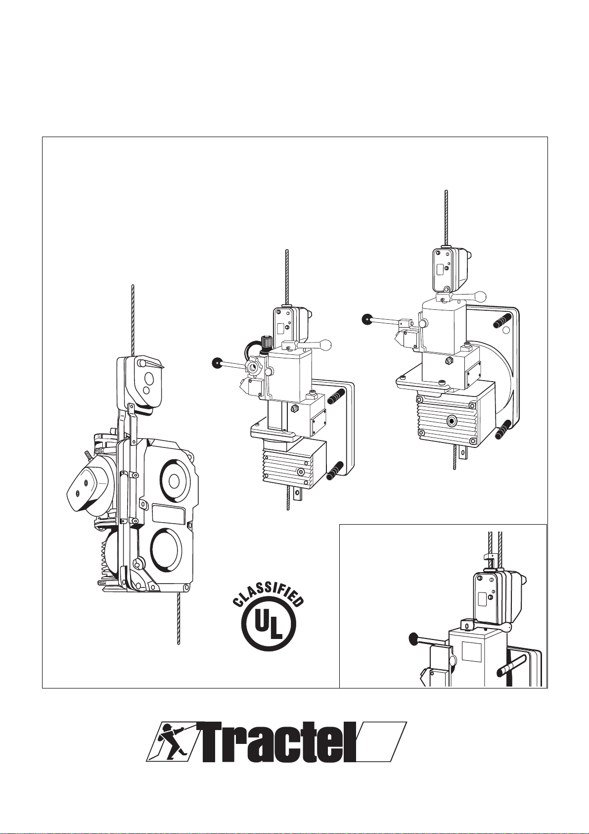
tirak®
Scaffolding Hoist
Instruction Manual
Inc.
XA 300/500/700 series
including BLOCSTOP®
BS/BSO on
2 wire rope
system
TA 1000 P
including
BLOCSTOP®BSO
XA 300 P
including
BLOCSTOP®BSO
XA 500 P
XA 700 P
XA 1020 P
including
BLOCSTOP®BSO
Griphoist
®
Division
www.tractel.com
®
2
Explanation of Symbols used in this manual
INTRODUCTION
...............................................................
3
1. GENERAL WARNING
.............................................
4
2. DESCRIPTION
2.1 Motor and Primary Brake........................................6
2.2 Gear Reducer .......................................................... 6
2.3 Secondary Brake .....................................................6
2.4 Emergency Descent without power .......................6
2.5 Wire Rope Driving Mechanism............................... 6
2.6 Wire Rope ................................................................6
2.7 Technical Data.........................................................7
3. RIGGING INSTRUCTIONS
3.1 General
3.1.1 Scope ............................................................8
3.1.2 Checks before rigging..................................8
3.2 Air supply and hoist control
3.2.1 Air supply ......................................................9
3.2.2 Air preparation unit ......................................9
3.2.3 Air hoses.......................................................9
3.2.4 Hoist Control...............................................10
3.3 Hoist Mounting
3.3.1 TIRAK
®
X-Series ........................................11
3.3.2 TIRAK
®
T-Series.........................................11
3.3.3 Connection to the air supply .....................12
4. WIRE ROPE
4.1 Wire Rope Specification .......................................13
4.2 Wire Rope Rigging Instructions............................13
4.3 Wire Rope Reeving ...............................................15
4.4 De-Rigging .............................................................16
5. OPERATING INSTRUCTIONS
5.1 General ...................................................................16
5.2 Normal Operation ................................................... 17
5.3 Emergency descent................................................18
5.4 BSO Secondary Brake Action................................18
6. TROUBLE SHOOTING
6.1 Mechanical .............................................................19
6.2 Motor troubles ........................................................19
6.3 BLOCSTOP BSO secondary Brake.......................20
7. INSPECTIONS and MAINTENANCE
7.1 Inspections
7.1.1 Daily Inspections.........................................21
7.1.2 Monthly Inspections ....................................22
7.1.3 1/2-Year Inspection.....................................23
7.2 Maintenance
7.2.1 TIRAK
®
Hoist ............................................... 22
7.2.2 Wire Ropes .................................................22
7.2.3 BLOCSTOP BSO Secondary Brake...........22
ADDITIONAL INSTRUCTIONS for
TIRAK®including BLOCSTOP BS/BSO
.........21 to 43
8. NAMEPLATES & LABELS
.................................38
9. WARRANTY INFORMATION
.............................
40
10. ADDITIONAL SOURCES AND TRAINING
...
41
SCAFFOLD SAFE PRACTICE GUIDELINES
.....42
TABLE OF CONTENTS
Safety advice
Symbol Code word Meaning Possible consequence of non-compliance
IMMEDIATE or
WARNING possibly imminant Fatal or serious injuries!
danger:
CAUTION possibly dangerous Injuries to persons
situation: or damage to property
Other advice
NOTE possibly dangerous Damage to equipment
situation: or its surroundings
Instruction to execution/
(none) documentation in writing (none)
(i.e. record keeping)
3
INTRODUCTION
Based on an original design, TIRAK
®
wire rope scaf-
fold hoists are specially manufactured for lifting
personnel in a suspended platform system.
For that purpose they are UL classified.
TIRAK
®
hoists are composed of the fol-
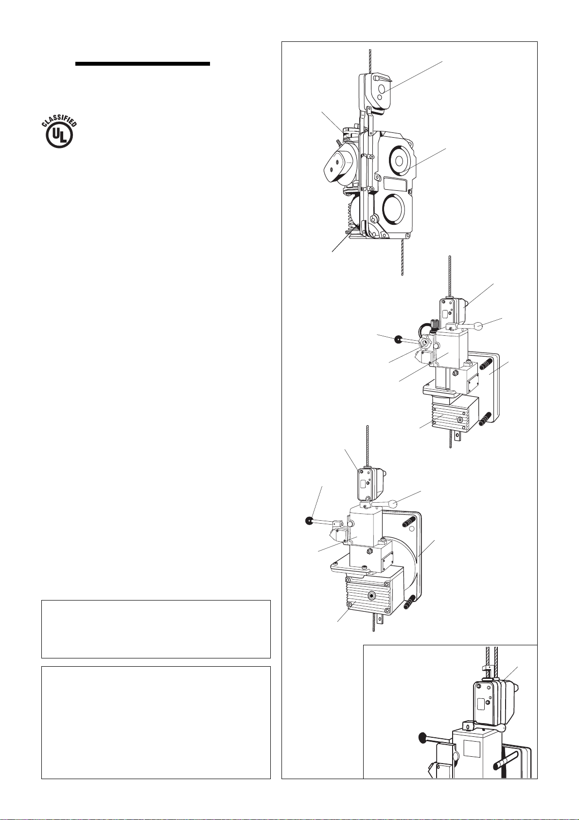
lowing main assemblies (Fig. 1):
A Wire rope driving mechanism
B Gearbox
C Air motor with primary brake
D BLOCSTOP
®
BSO secondary brake, or
E BLOCSTOP BS/BSO secondary brake
F Air hose coupling
G Control lever
H Brake release lever
The main advantages of TIRAK
®
hoists are:
– PowerfuI, fast, and lightweight.
– Simple, rugged, and reliable.
– Unlimited lifting height.
– Constant speed on any height.
– Gentle for its wire rope.
– Mechanical emergency descent device.
The secondary brake (D) or (E), marked
BLOCSTOP
®
BSO or BS/BSO MUST ALWAYS BE
ATTACHED AND USED.
The original design requires, for safety and
efficiency, that it be used with a special TIRAK
®
wire rope specified by the Manufacturer
1)
.
TIRAK
®
hoists are intended to be used for work
going up and down a vertical hanging wire rope.
TIRAK
®
hoists are designed to be rigged to a
compatible platform, workcage or bosun’s chair.
This manual gives the required information for
rigging, operating and maintaining the TIRAK
®
hoists. Responsibility for the complete suspended
platform system lies upon the rigger of that system.
1) “Manufacturer” definition:
Greifzug Hebezeugbau GmbH
Postfach 20 04 40
51434 Bergisch Gladbach Germany
Fig. 1
TA 1000 P
A
XA … series
incl. BLOCSTOP®
BS/BSO on
2 wire rope
system
D
C
A
BD
B
C
A
C
B
E
XA 500 P
XA 700 P
XA 1020 P
XA 300 P
F
GH
H
G
D
“Supplier” definition regarding contact advice in this manual:
TRACTEL Inc. Griphoist® Division
110 Shawmut Rd. P.O. Box 68 • Canton, MA 02021
Tel.: (800) 421-0246 • Fax: (781) 828-3642
Email: [email protected]
Branch office:
315 Cloverleaf Dr., Unit E • Baldwin Park, CA. 91706
Tel.: (800) 675-6727 • Fax: (626) 937-6730

4
1. General Warning
READ THIS GENERAL WARNING FIRST
IN SUSPENDED SCAFFOLD OPERATIONS, SAFETY IS A MATTER OF LIFE OR DEATH
FOR RIGGERS, OPERATORS AND BY-STANDERS.
THIS WARNING IS YOUR SHARE OF DUTIES FOR ACHIEVING SAFETY.
1. It is the rigger’s and the operator’s responsibil-
ity, and their employer’s responsibility, if they
operate under an employer’s control, to strictly
conform to the following warnings.
2. It is imperative for safety and efficiency of the
operations that this manual be read and fully
understood by the rigger and the operator
before rigging or operating the TIRAK
®
. ALL
instructions contained herein must be carefully
and strictly followed, including applicable S.I.A.
guidelines for safe practice (see pages 41 and
42).
3. Should you hand over a TIRAK
®
, under what-
ever conditions, to any party operating out of
your control, you must join a clean copy of this
manual and draw other party’s attention that
strictly following all the instructions therein is
a matter of life or death.
4. Before rigging and operating this TIRAK
®
hoist, the rigger and the operator must
become aware of all the requirements of
federal, state, provincial and local safety
regulations not only applicable to the TIRAK
®
hoist but also to the entire suspended scaffold
system and any component of it.
5. Never use the TIRAK
®
hoist for any job other
than lifting personnel on suspended scaffold
according to the instructions of this manual
6. Never load the TIRAK
®
hoist above its rated
load.
YOUR DUTY TO UNDERSTAND AND COMPLY
7. Keep this manual available at all times for easy
reference whenever required. Extra copies are
available from the supplier.
8. Carefully take notice of all the labels affixed to
the TIRAK
®
. Never rig or operate the hoist if any
label, normally fixed on the hoist is obscured or
missing (see page 38 and 39). The supplier will
supply extra labels on customer’s request.
9. Every time the hoist is to be rigged or used,
check that the hoist, wire rope and other
components of the suspended scaffold system
are complete and in good working condition,
prior to proceeding.
10. A careful and regular inspection of the TIRAK
®
hoist, its wire rope and other components of
the installation is part of the safety
requirements. If you have any questions, call
the supplier.
11. After each de-rigging and before re-rigging,
the TIRAK
®
must be inspected by a competent
person familiar with the TIRAK
®
hoist and
professionally trained for the purpose.
YOUR DUTY TO INSPECT AND MAINTAIN
12. An operator must not be assigned to a sus-
pended job or to rigging for a suspended job, or
to de-rigging after the job, if that person is not:
a) mentally and physically fit for the purpose,
specially at heights,
b) competent for the job to be performed,
c) familiar with all applicable safety rules and
requirements,
d) familiar with the scaffold equipment as rigged,
e) provisionally trained for working under the
above requirements.
13. Never disassemble the TIRAK
®
by yourself or
by your staff. People’s life may be at risk.
Except for the operations described in this
manual, the maintenance of the TIRAK
®
hoists, as well as disassembly and repair,
must be exclusively done by qualified repair-
ers authorized in writing by the supplier.
TIRAK
®
spare parts in accordance with the
serial number of each machine must be ex-
clusively utilized. No substitutions are allowed.
14. Never let the TIRAK
®
hoist and other equip-
ment of a suspended scaffold system be
managed or operated by a person other than
authorized and assigned to the job. Keep the
equipment, either rigged or unrigged, out of
reach of unauthorized persons, while out of
operation.
YOUR DUTY TO TRAIN AND CONTROL PEOPLE

5
23. The BLOCSTOP
®
BSO or BS/BSO secondary
brake located at the upper part of the unit is an
integral piece of the TIRAK
®
hoist. It is strictly
forbidden to detach it from the main body of the
hoist for whatever reason. Doing so would be a
misuse creating an extreme hazard and placing
operators and by-standers in danger of death
resulting from the possible fall of the suspended
equipment: scaffold, workcage, bosun’s chair or
any other items or components.
24. Once the suspended scaffold, work-cage or
bosun’s chair has been lifted off its initial support
(ground or any other level), it is imperative not to
release, remove, alter or obstruct any part of the
equipment under load.
25. NEVER allow any condition which would result
in a suspension wire rope becoming SLACK
during the operation, unless …:
YOUR DUTY TO AVOID TAKING CHANCES
a) … the suspended scaffold, work-cage or
bosun’s chair is supported on a safe surface
giving a safe access to the operator in
compliance with safety regulations, or
unless …
b) … another suspension wire rope has been
safely rigged to the suspended scaffold,
workcage or bosun’s chair.
26. For any job to be performed on the suspended
equipment, consider and control the specific
risks related to the nature of the job.
27. Should you decide that the TIRAK
®
hoist is no
longer to be used, take precautions in
disposing of it so that it cannot be used any
more.
AN ULTIMATE RECOMMENDATION
Never neglect means to improve safety. Due to the risks inherent in the use of suspended scaffold
systems, the supplier strongly recommends that every installation be equipped with secondary wire
rope(s) fitted with a separate fall arrest system. Details about TIRAK
®
with BLOCSTOP
®
BS/BSO
secondary brake on 2 wire rope systems at pages 24 to 37.
This manual is neither a regulations compliance manual nor a general training guide on suspended
scaffold operations. You must refer to proper instructions delivered by manufacturers of the other
pieces of equipment included in your suspended scaffold installation. Whenever calculations and
specific rigging and handling are involved, the operator should be professionally trained to that end and
secure relevant information prior to commencing such work.
15. Training operators and riggers includes setting
up rescue procedure should a scaffold be brought
to a standstill during a job. Such procedure must
be set up by a competent person of the user, or
of its technical consultant, according to the work-
ing conditions, prior to putting the equipment
into operation.
16. Every suspended job must be placed under
the control of a person having the required
competence and the authority for checking
that all the instructions prescribed by this
manual be regularly and efficiently carried out.
YOUR DUTY OF SAFETY BEYOND THE TIRAK
20. … supporting structure and tie-back provide
the requested resistance to every load to be
applied, either static or dynamic, during rigging
or operating the scaffold equipment;
21. … all the requirements in strength and
resistance are obtained with the necessary
safety factor (see regulations and professional
standards);
22. … all the calculations, design and subsequent
work necessary to the above requirements
have been made by a competent person on
the basis of proper technical information
regarding the site.
As being only one piece of the scaffold system,
the TIRAK®hoist can contribute to the required
safety only, if ...:
17. … it is fitted on compatible scaffold equipment,
including the wire rope used in the TIRAK
®
hoist.
18. … other components meet the requirements of
the applicable safety regulations and are of the
proper quality, and assembled to form a safe
suspended scaffold system.
19. … every upper support of the scaffold is stable,
sufficiently strong and properly tied back to the
structure, according to the load either static or
dynamic.

6
2. DESCRIPTION
2.1 Motor and Primary Brake
TIRAK
®
hoists are driven by a air motor with
a mechanically actuated brake. Electric
TIRAK
®
are available also.
2.2 Gear Reducer
The gear reducer consists of a worm gear
drive in connection with a spur gear, oil bath
lubricated in a sealed aluminum casing.
2.3 Secondary Brakes
The BLOCSTOP
®
BSO overspeed locking
device (D) – hereafter called BSO second-
ary brake – stops the descent immediately
in case of accelerating overspeed.
The BLOCSTOP
®
BS/BSO overspeed and
slack wire rope locking device (E) – here-
after called BS/BSO secondary brake –
additionally provides protection against slack
wire rope or primary wire rope failure, when
using secondary wire ropes.
SECONDARY BRAKES MUST ALWAYS BE
ATTACHED AND USED.
2.4 Emergency Descent
In case of emergency manual descent is
possible at moderate speed, which is con-
trolled by the braking effect of the motor
itself. No handcranking is needed.
2.5 Wire Rope Driving Mechanism
The wire rope enters the hoist from the top,
is led through by the patented driving sys-
tem, and exits opposite its entry. As the wire
rope is not stored inside the hoist, its length
(i. e. the possible rope travel) is unlimited on
principle. The driving system is independent
of the load applied to the wire rope. The
whole mechanism is housed in an aluminum
casing.
2.6 Wire Rope
TIRAK
®
hoists use a Special TIRAK
®
Wire
Rope (see chapter 4). Unless specificly speci-
fied in writing by the manufacturer, only this
special TIRAK
®
wire rope may be used.
NOTE: The manufacturer declines all re-
sponsibility for machines used
with a wire rope other than speci-
fied by them.
a1
A
c2
C
TA 1000 P
XA … series
for 2 wire rope
system
E
D
XA 300 P
B
C
A
B
a1
D
C
Dd2
d1
A
B
XA 500 P
XA 700 P
XA 1020 P
AWire rope driving mechanism
a1 Stirrup adapter (X-Series)
BGearbox
CMotor with brake
c1 Control lever UP / DOWN
c2 Brake release lever
DBLOCSTOP BSO
secondary brake
d1 Control lever
d2 EMERGENCY STOP
on the BLOCSTOP
E BLOCSTOP®BS/BSO
secondary brake
Fig. 2
c1
c1 c2
7
wire rope classification/ 5 x 19, 4 x 26, 5 x 26, with fiber core,
construction or 6 x 19 (min. 17 wires per strand),
galvanized or black, lubricated,
preformed, IPS or XIPS
nominal diameter in./mm 5/16 in. / 8.4 mm 3/8 in. / 9.5 mm
allowable diam. range in. 0.319 to 0.331 0.362 to 0.374
of new wire rope mm 8.1 to 8.4 9.2 to 9.5
minimum actual lbs 10,000 15,000
breaking strength kN 44.5 66.8
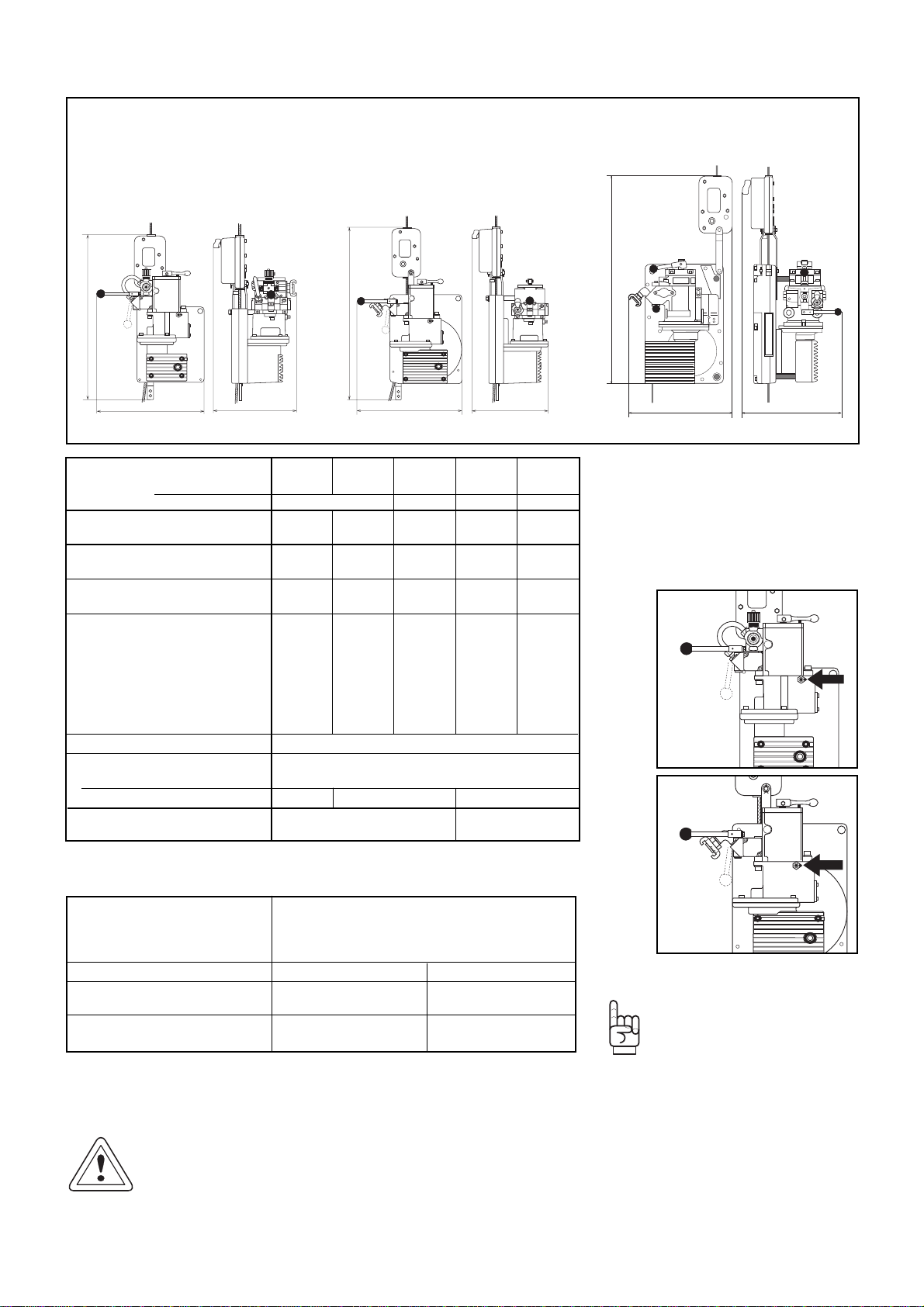
2.7 Technical Data
Fig. 3 Dimensions
XA 300 P
including
BLOCSTOP®
BSO
TA 1000 P
TA 1020 P
incl. BLOCSTOP®BSO
XA 500 P
XA 700 P
XA 1020 P
incl. BLOCSTOP®BSO
b
a
c
b
a
c
c
b
a
TIRAK®Model direct control
XA 300 P XA 500 P XA 700 P XA 1020 P TA 1020 P
remote control
XA 300 PB XA 500 PB XA 700 PB XA 1020 PB TA 1020 PB
including BLOCSTOP
®
Model BSO 500 BSO 1000 BSO 1020
Rated load lbs 700 1,000 1,500 2,000 2,000
kg 315 450 680 900 900
Lifting speed ft/min 33 35 30 23 35
m/min 10 11 9 7 11
Weight (with BSO) lbs 67 91 91 91 172
kg 30 41 41 41 78
Dimensions over all a in. 30.7 33.5 33.5 33.5 34.9
mm 779 858 858 858 886
b in. 15.9 16.9 16.9 16.9 16.5
mm 403 430 430 430 420
c in. 13 14 14 14 14.3
mm 330 354 354 354 362
Motor specifications air motor
Maximum rated
inlet pressure psi 85
Minimum quantity cfm 46 64 100
wire rope in. 5/16 3/8
diameter mm 8.4 9,5
Table 2
Table 1
Note: DO NOT alter the preset
adjusting screw marked
with red sealing wax
(see Fig. 4 and 5).
Fig. 4
XA 300
Fig. 5
XA 500
XA 700
XA 1020
CAUTION:
Correct wire rope diameter within the allowable
diameter range is very important for the TIRAK
®
function!
UNDERSIZED
wire rope may cause slippage in
the hoisting mechanism and in the BSO second-
ary brake.
OVERSIZED
wire rope may cause dam-
age to the guide band and other internal
parts or jam in the hoist causing dam-
age to the wire rope itself!
It also may cause the BSO secondary
brake to malfunction.

8
3. RIGGING INSTRUCTIONS
3.1 GENERAL
3.1.1 Scope
Instructions and advice in this manual exclusively
refer to the following items (Fig. 4):
–TIRAK scaffold hoist
with BLOCSTOP
®
BSO secondary brake
or BS/BSO
1)
secondary brake;
–Special TIRAK wire rope;
–Air supply hose.
1) Instructions and advice for TIRAK
®
including BLOCSTOP
®
BS/BSO
secondary brake for 2-wire-rope-systems
see seperate instructions
on pages 24 to 37.
3.1.2 Checks before rigging
It is a qualified person’s responsibility to check the
whole installation to meet all safety requirements of:
– OSHA regulations and federal, state, provincial
or local safety regulations,
– the proper instructions delivered by the manufac-
turers of the other pieces of equipment included
in your suspended scaffold installation.
Some pieces are:
– Support equipment including tie-back;
– platform system, work-cage, or bosun’s chair;
– safety equipments (personal fall arrest system);
– barricade below the drop of the platform/work-
cage/bosun’s chair.
NOTE: This information is NOT to be considered as
a complete checklist for your specific installa-
tion. It is only a sample list of some general
components, which make part of a typical sus-
pended scaffold installation (Fig. 5).
Fig. 6 Relevant Items (principle sketch)
Air Power
supply hose
Special
TIRAK
®
wire rope
Fixing the
wire rope to the
support equipment
Connecting
TIRAK
®
and
platform system
TIRAK
®
with
BLOCSTOP
®
BSO
secondary brake
Lifeline
Tie-back Support
equipment
Special
TIRAK
®
wire rope
TIRAK
®
with
BLOCSTOP
®
BSO
Suspended
platform
system
Air
supply
hose
Barricade
Fig. 7 Typical suspended scaffold installation
Personal
Fall Arrest
System
9
3.2 Air supply and hoist control
3.2.1 Air Supply
Check that the compressed air supply meets
the following requirements :
Fig. 8
Maximum rated
inlet pressure 85 psi *)
Minimum quantity
XA 300 P 46 cfm
XA 500 to 1020 P 64 cfm
TA 1000 P 100 cfm
WARNING
Never disconnect the air supply
unless :
1) The air compressor has been shut off or the
connection to the supply system has been in-
terrupted with a shut-off valve.
2) All air pressure has been bled from the supply
lines.
Table 3
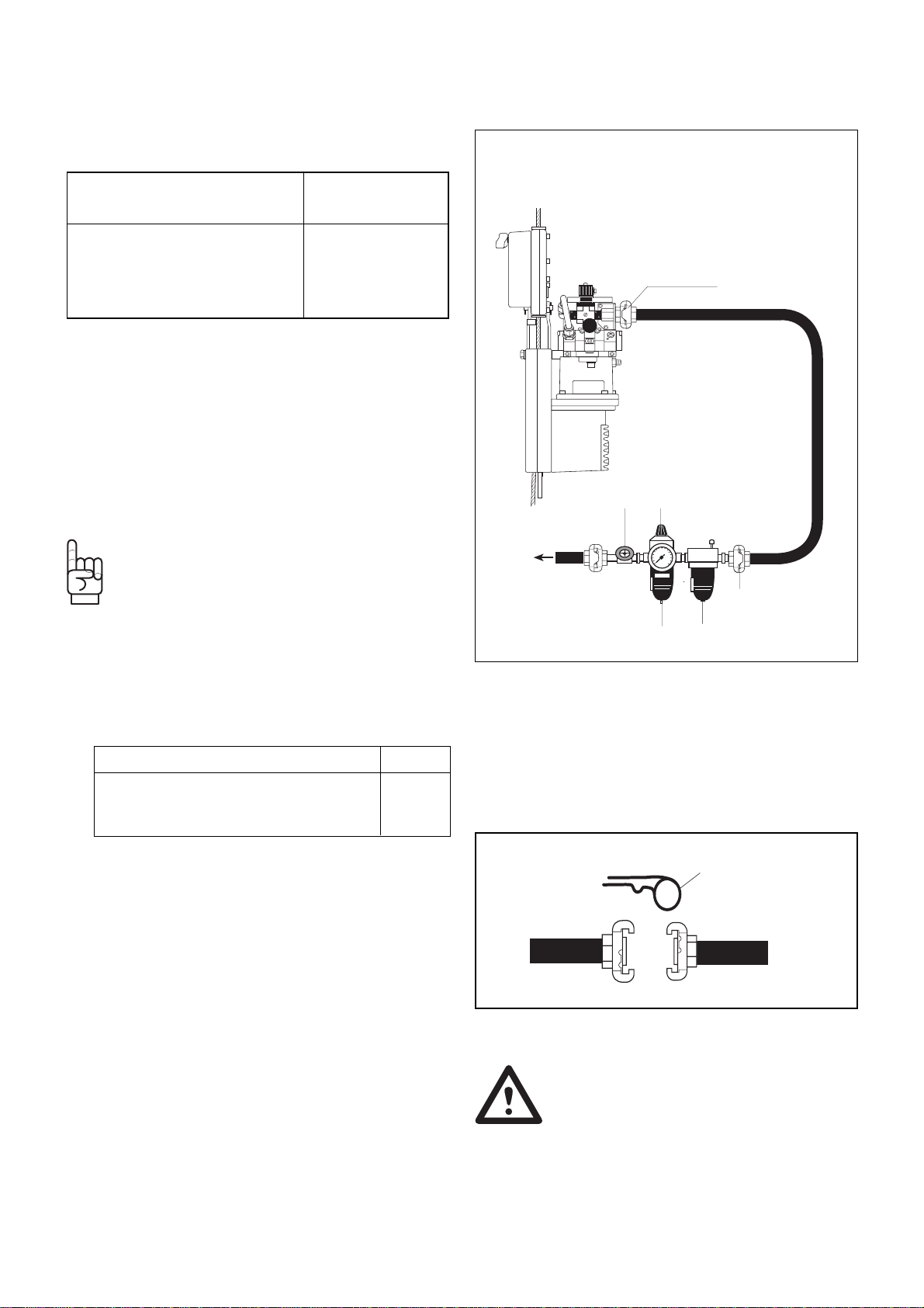
Hose connection
between hoist and
air preparation unit
as short as possible
Water Separator
and Oiler
Air Preparation Unit
to
air
supply
Manometer
3/4 " coupling
Filter and
Regulator
Shut-off valve
3/4 " coupling
3.2.2 Air preparation unit
The compressed air must be dry and well oiled. To
guarantee this install an air preparation unit with water
separator/filter, pressure regulator and oiler directly
before the TIRAK
®
(Fig. 8).
This precaution ensures the longevity of the air motor.
NOTE: Higher pressure from the supply system
(max. 230 psi) must be reduced to the required
85 psi by means of the pressure regulator.
3.2.3 Air Hoses
1) Before starting the operation blow through the air
supply hose leading from the air preparation unit
to the TIRAK
®
to avoid impurities entering motor.
For trouble free working, the supply hoses must
have the minimum rated cross sections:
From air preparation unit to TIRAK
®
3/4 "
When running two TIRAK
®
from one
compressed air supply, between 1 "
air supply and air preparation unit
The TIRAK
®
is outfitted with a 3/4 " coupling .
Be sure that all connectors, hoses and inline valves
are rated for a minimum pressure of 200 psi.
Couplings must be secured with hairpins (Fig. 9).
2) Connect and lock all air lines from the air supply to
the air preparation unit using a locking pin. Install
relief devices across them.
a) Start the compressor and slowly apply air pres-
sure to the hoses.
b) Blow through the air supply hose leading from
the air preparation unit to the hoist to avoid im-
purities entering the motor.
c) Inspect all air hoses to ensure that they are in
good conditions and that connections are not
leaking.
d) By means of the regulator, adjust the supply
system to the required 85 psi.
*) The TIRAK
®
will lift capacity at a reduced
speed with a minimum pressure of 55 psi.
Table 4
Locking-pin
Fig. 9
10
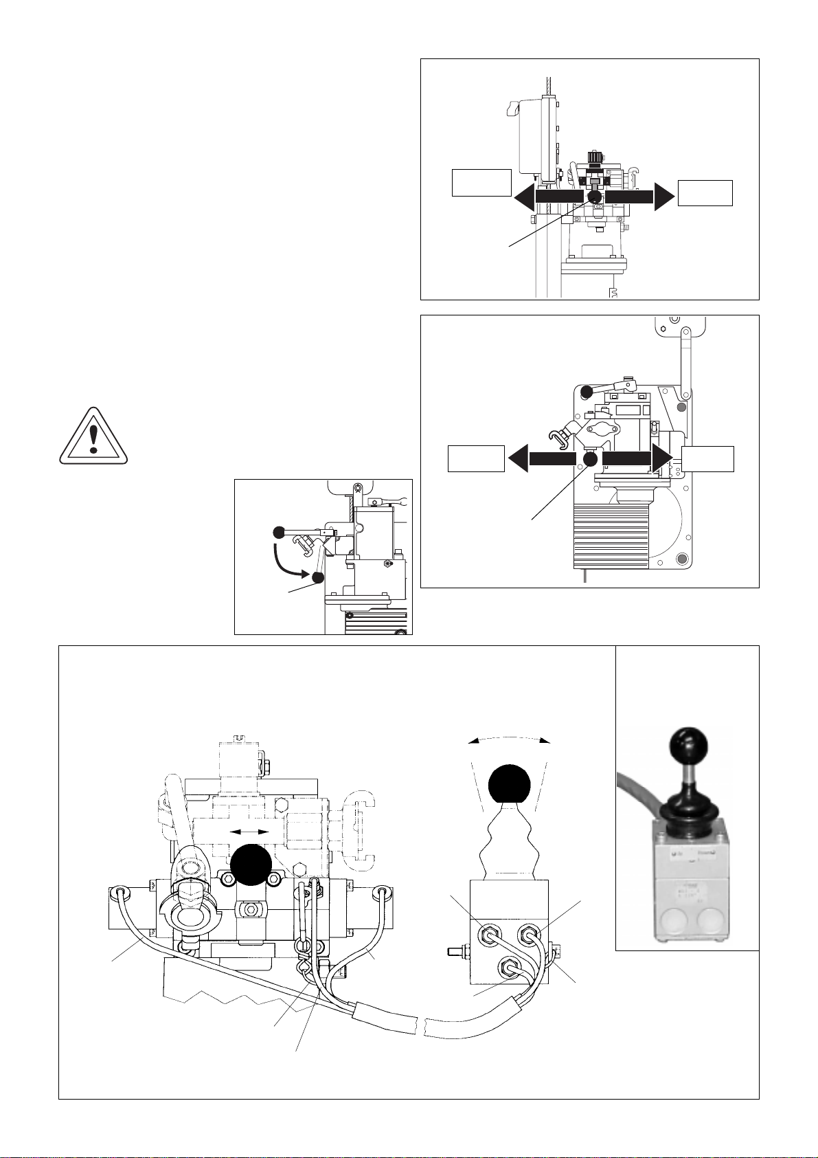
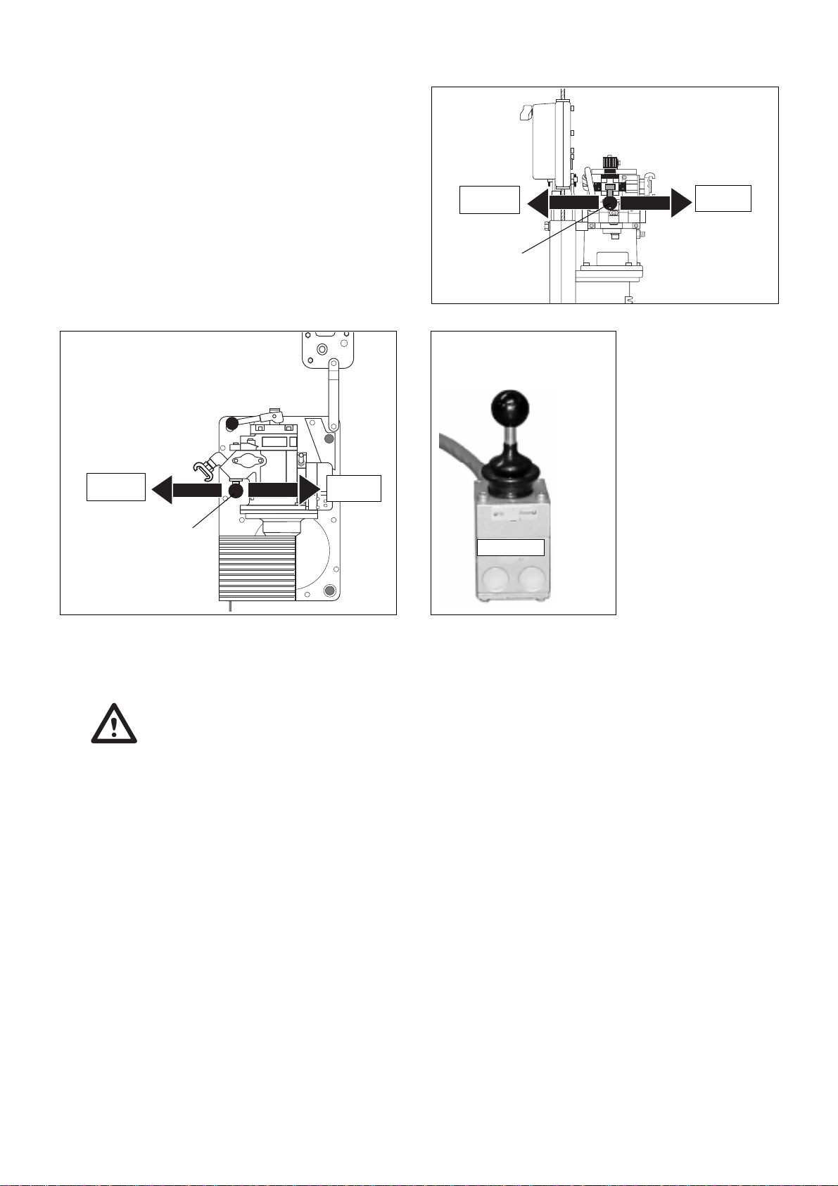
3.2.4 Hoist Control
The TIRAK
®
control is effected
– by means of a "two-way" hand lever on the motor
(Figs. 10 to 12), or
– by means of a remote control valve (Fig. 13), con-
nected to the motor with three flexible hoses inside
a covering hose with steel wire rope for strain relief.
Connection to the motor by self-gripping couplings;
transparent hose = air inlet,
blue hose = UP control,
red hose = DOWN control.
To reeve or climb the TIRAK
®
move and hold the control
lever/valve to the UP-position. To descend or unreeve
move and hold the control lever/valve to the DOWN-
position.
The control lever/valve is spring actuated so that, when
released, it will return to the neutral position and the
mechanical brake automatically stops travel
CAUTION!
DO NOT fix any hoi8st control lever
in the UP or DOWN position.
To avoid damage during
transport the Control lever
of all TIRAK
®
Hoists can
be turned into a storage
position.
See the example for the
XA 500 P in (Fig. 12).
Fig. 10
XA series
down up
Control
lever
Fig. 11
Control
lever
TA Series
down up
Fig. 12
Control
lever
Fig. 13
Remote control
XA Series
red
red
blue
blue
transparent
transparent
Strain relief
Strain relief
down up
Fig. 13a
Remote control
reverse siede view with
“UP / DOWN” marking

11
Fig. 14
Hoist
mounting
TIRAK
®
X-series
Fig.15
Hoist
mounting
TIRAK
®
T-series
90
°
Anchor
pin
Stirrup
90
°
Stirrup
adapter
3.3 Hoist Mounting
3.3.1 TIRAK®X-series
Bolt the hoist to platform stirrup us-
ing stirrup adapter, which also
holds the hoist in its upright position
(see Figs. 14 and 16).
Use two 1/2 inch diameter grade 5
or better bolts with locking nuts.
WARNING:
HOIST CONNECTION
BOLTS MUST NOT
BEAR ON THREADS.
Ø d
e
f
a
1
a
3
XA 300 P
a
1
= 4.41 in. / 112 mm
a
2
= 3.94 in. / 100 mm
a
3
= 3.86 in. / 98 mm
b = 1.58 in. / 40 mm
c
b
Fig. 16 Dimensions of connecting parts (stirrup adapter)
TIRAK
®
X-series
Ø d
b
efa
2
a
3
c
XA 500/700
series
c = 0.47 in. / 12 mm
d = 0.51 in. / 13 mm
e = 1.36 in. / 32 mm
f = 1.02 in. / 26 mm
Fig. 17 Dimensions of connecting parts
TIRAK
®
T-series
Anchor pin Ø:
0.63 in. / 16 mm
Anchor hole Ø:
0.65 in. / 16.5 mm a = 1.1 in. / 28 mm
b = 0.55 in. / 14 mm
a
bb
3.3.2 TIRAK®T-series
Fix the hoist using its anchor pin (see Fig. 15 and 17).
Make sure that the hoist is held in its upright position
by means of an appropriate support. The anchoring
device must attach to the pin between the 2 cast ears
“b” of Fig. 19.
WARNING:
THE HOIST MUST BE MOUNTED SUCH
THAT THE WIRE ROPE PERPENDICU-
LARLY ENTERS THE HOIST.
(Figs. 14 and 15)
Fig. 18 Special rigging arrangement
NOTE: Any rigging ar-
rangment other than
described in this manu-
al is entirely under the
rigger’s responsibility.
For special projects like
shown in Fig. 20 contact the
supplier for additional in-
formation.

12
3.3.3 Connection to the air supply
1) Attach air hoses and air preparation unit to the
work platform. It is important that all air line con-
nections are locked and supported by a strain
relief device. The weight of the air line must not be
carried by the TIRAK
®
hoist power inlet connec-
tion.
2) Before connecting the hoist :
a) Start the compressor and slowly apply air pres-
sure to the hoses.
b) Blow through the air supply hose leading from
the air preparation unit to the hoist to avoid
impurities entering the motor.
c) Shut off the compressor and let all air pressure
be bled from the supply lines.
d) Pour a small amount of oil into the air hose.
e) Connect air hoses to the hoist.
3) After all connections are made :
a) Start the compressor and slowly apply air pres-
sure to the hoses.
b) Inspect all air hoses to ensure that they are in
good condition and that connections are not
leaking.
c) By means of regulator, adjust the supply sys-
tem to the required 85 psi
d) Run the motor for approx. 2 seconds to let the
oil completely distribute in the air motor. This
means higher performance and an increase in
service life.
4. Wire Rope
4.1 Wire rope specification
Use only wire ropes specified by the manufacturer:
(1) Classification/Construction:
5x19, 4x26, 5x26, with fiber core, or 6x19 (min.
17 wires/strand), galvanized or black, lubricated,
preformed IPS or XIPS.
Figure 19 Checking Wire Rope Diameter “d”
Incorrect
CORRECT
Figure 20 Wire Rope Handling
d
(2) Diameter:
CAUTION: Correct wire rope diameter within the
allowable diameter range is very impor-
tant for the TIRAK
®
function!
UNDERSIZED
wire rope may cause slip-
page in the hoisting mechanism and in
the BSO secondary brake.
OVERSIZED
wire rope may cause dam-
age to the guide band and other internal
parts or jam in the hoist causing damage
to the wire rope itself!
It also may cause the BSO secondary
brake to malfunction.
NOTE: How to measure wire rope diameter:
The correct diameter of the wire rope is
the largest cross-sectional measurement
across the strands (and not the valleys).
The measurement should be made care-
fully with calipers as shown in Fig. 19.
1) Allowable diameter range of NEW wire rope:
5/16 in. (8.4 mm) = 0.319 to 0.331 in. (8.1 to 8.4 mm)
3/8 in. (9.5 mm) = 0.362 to 0.374 in. (9.2 to 9.5 mm)
Table 5: Wire Rope Diameter and min. actual Breaking Strength
wire min. actual for TIRAK
®
hoists
rope breaking with
diameter
1)
strength rated load up to
5/16 in. 10,000 lbs 1,500 lbs
8.4 mm 44.5 kN 680 kg
3/8 in. 15,000 lbs 2,000 lbs
9.5 mm 66.8 kN 900 kg
4.2 Wire rope rigging instructions
WARNING :
Be sure to use a wire rope with the
diameter marked on the TIRAK®
nameplate.
CAUTION:
Always unreel and reel the wire rope
in a straight line (Fig. 20) to prevent
kinks, which make it unusable for
the hoist.
(1) RIG FROM TOP.
You should have enough wire rope to reach to the
ground or other safe level with about five feet
(1.5 m) extra for ensuring safety.
13
4.2 Wire rope rigging instructions
(continued)
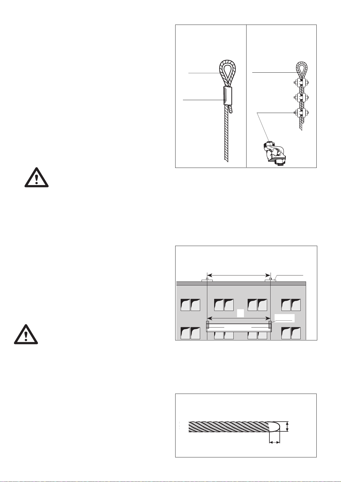
(2) If the wire rope is not equipped with a swaged
fitting as shown in Fig. 21, proceed as follows:
– Install heavy duty thimble with a minimum of
three (3) J-Type (Fist Grip) Clamps (Fig. 22).
– Apply first clamp approximately 7" (18 cm) from
thimble. Tighten nuts moderately.
– Attach second clamp as close to thimble as pos-
sible. Leave nuts loose.
– Attach the third clamp half-way between first
and second clamp, leaving the nuts loose. Take
up wire rope slack.
– Tighten nuts evenly on all clamps (approx.
30 ft-lbs. torque) as specified by the clamp manu-
facturer.
WARNINGS:
a) Retighten after the wire rope is loaded for
the first time
b) Inspect fastening periodically. In use, wire
ropes will stretch and reduce in diameter.
Retighten all “Fist Grip” nuts periodically.
(3) Anchor the wire rope end to a rigging device,
which complies with all relevant safety require-
ments.
Be sure to use compatible connecting devices,
e.g. a 1/2 in. anchor shackle or similar with ad-
equate strength and safety factor. Secure it.
(4) Insure that the anchor points of the wire ropes
are directly above the position of the hoists
(Fig. 23).
WARNING:
Improper spacing is dangerous, and
could cause failure of the support system.
Fig. 24 Wire Rope Tip
Same distance
X
Platform
Support
system
Hoist
X
Fig. 23 Suspension Distance
Fig. 22
Wire Rope Termination
by Fist Grip Clamps
Fig. 21
Wire Rope Termination
by Swaged Fitting
Fist Grip Clamp
Heavy duty
thimble
Heavy duty thimble
Ferrule
(Sleeve)
4 in. (10 cm) Straight
max. 1
1
/
2
dia.
dia.
(5) Check that wire rope tip is welded round.
(Fig. 24)
IF NOT:
a) Prepare ends by brazing or welding – make
sure all end wires are captured.
b) Grind end to approximately 1/4" diameter.
DO NOT grind end flat or to a cone shape. End
must be rounded (Fig. 24).
c) The last 4 in (10 cm) of the wire rope must be
straight for proper reeving.
14
4.4 De-Rigging
(1) Before de-rigging each TIRAK
®
hoist must be
unloaded by bringing down the platform to a safe
and stable support.
(2) Remove the loop at the free wire rope end.
(3) Push Control lever into DOWN-position to let the
wire rope run out.
(4) With gloved hands slowly pull the wire rope through
BSO secondary brake.
(5) Clean the wire rope, reel it (see Fig. 22, page 12),
and store it in a clean and dry place.
Fig. 25 Opening of BSO Secondary Brake
(d1) Closed
(d1) Open
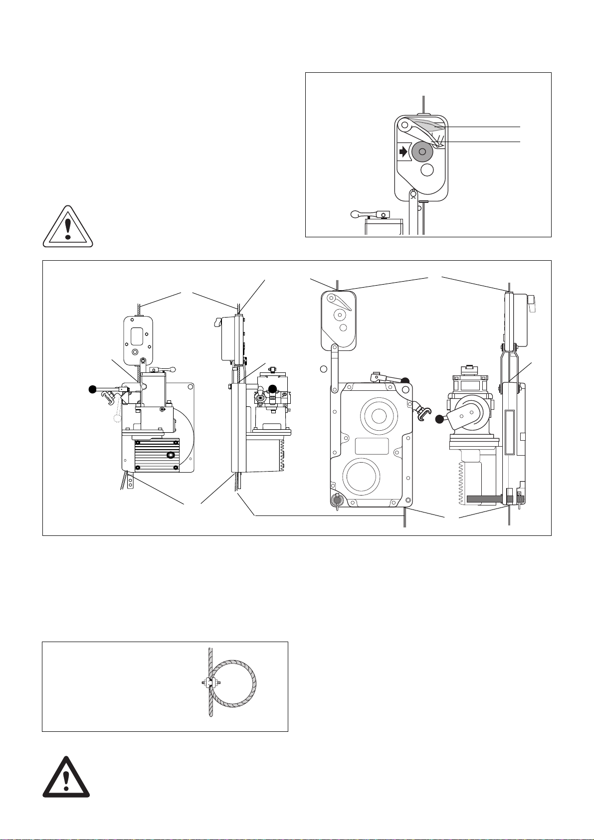
4.3 Wire rope reeving
(1) Open the BSO secondary brake by pushing down
the control lever (d1) until it locks (Fig. 25).
(2) With gloved hands push the rope through the BSO
secondary brake at (A) into the hoist rope inlet (B).
Push it inside, and push control lever/valve in UP-
position, until the wire rope reeves itself
automatically and exits at (C) on the other side
(Fig. 26).
CAUTION: Check that wire rope exit (C) is not
blocked in any manner.
Never load the wire rope exiting
from (C), by applying a load to it
or tensioning.
(3) After reeving through the hoist, be sure to loop
and clamp the free end of the wire rope, to prevent
the rope from, inadvertently unreeving through the
hoist.
Always tie this loop, using a fist grip clamp, when
the platform is at ground level or other safe sur-
face (Fig.27).
B
Fig. 26 Wire rope reeving
A
B
C
TIRAK
X-Series
A
C
B
TIRAK
T-Series
R
Entrance wire rope
Exit wire rope
Must not be loaded!
Fig. 27 Loop at free wire rope end
Bottom free end of wire rope
Fist grip clamp
WARNING: AT EVERY SET-UP OR RERIGGING
check the wire rope length to ensure
that it reaches the ground or other
safe level with about five feet
(1.5 m) extra for safety.

15
5. Operating Instructions
5.1 GENERAL
(1) BE FAMILIAR with the equipment and its proper
care.
DO NOT operate hoist, if adjustment or repairs are
necessary, if any warning, operating or capacity
label normally attached to the hoist is obscured,
damaged, or missing.
(See labels’ list on page 37).
REPORT same promptly to your supervisor and
also notify next operator, when changing shifts.
(2) WARNING:
SAFETY DEMANDS THAT YOU
TEST THE SYSTEM
BEFORE GOING ALOFT:
a) CHECK PLATFORM fully rigged and loaded by
cycling UP and DOWN several times near
ground level or safe surface.
b) CHECK PRIMARY BRAKE for mechanical func-
tion: When stopping the hoist the load must be
held immediately.
c) CHECK BSO SECONDARY BRAKE:
IAt ground level first close the BSO secondary
brake by pushing EMERGENCY STOP button
(d2). Then push the control lever/valve in
DOWN-position and make the wire rope form a
loop between TIRAK
®
casing and BSO second-
ary brake (Fig. 28). Open BSO secondary brake
by pulling down control lever (d1) until it locks
in the open position.
With gloved hands sharply pull wire rope in
arrow direction (Fig. 28) – the BSO secondary
brake should close immediately. Reset BSO
secondary brake by pulling down control lever
(d1) until it locks in the open position.
II Lift platform 3 ft. (1 m) above ground or safe
surface, and push EMERGENCY STOP button
(d2) of the BSO secondary brake (Fig. 29).
Try to lower the platform to check that the BSO
secondary brake holds the load.
A loop should form as shown in Fig. 28, which
means the BSO secondary brake is supporting
the load.
Raise platform until the hoist supports the load
Reset (d1) to the open position.
III During operation regularly check through the
window (d3) that the centrifugal weights are
rotating (Fig. 30).
Fig. 29
BSO Secondary Brake
Checks II + III
Fig. 28
BSO Secondary Brake
Check I
Wire rope loop
EMERGENCY
STOP (d2)
(d1) OPEN
(d1) Closed
(d1) Open
(d1) CLOSED
(d3) Window
EMERGENCY
STOP (d2)
WARNING: IF DURING ONE OF THE CHECKS
THE BSO SECONDARY BRAKE MAL-
FUNCTIONS, IT MUST BE RE-
PLACED.
d) Check that the Control lever return to the normal
position when released. It should move freely with-
out sticking.
Check that the Brake release lever also returns
back in normal position after pulling up.
WARNING: IF DURING ONE OF THE CHECKS
THE CONTROL LEVER OR THE
BRAKE RELEASE LEVER MAL-
FUNCTIONS, THE TIRAK®HOIST
MUST BE REPLACED.
e) CONTINUOUSLY CHECK rigging, lines, clear-
ances, and all other elements throughout the entire
time on the job.
16
5.2 Normal operation
(1) For UP and DOWNWARD MOTION of the plat-
form just push the control lever or control valve
lever in the corresponding direction.
(Figs. 30 to 32)
(2) When operating platform, take care to operate
hoists so that the platform stays level without tilt-
ing one end more than the other.
(3) When using the reomte control valve:
– Alway check the connections before using the
control valve.
– Take care of the connected air hoses, when
moving the remote control on the platform.
Fig. 30
XA series
down up
Control
lever
(3) WARNINGS
a) DO NOT fix Control lever in run position.
b) DO NOT operate the hoist, if it is functioning
improperly, or damage is noted.
c) NEVER pick up a load beyond the rated ca-
pacity appearing on the hoist.
d) STOP OPERATIONS IMMEDIATELY, if at any
time, when the hoist operates, the wire rope
does not move (i.e. no UP or DOWN travel).
It is likely that damaged wire rope is jam-
ming the hoist. Continued operation might
cause wire rope failure or damage to the
hoist.
CONTACT the SUPPLIER!
e) IN CASE OF AN INCIDENT involving injury,
or property damage, contact the supplier im-
mediately.
DO NOT disturb, alter, or move any equip-
ment at the scene of the incident.
Fig. 31
Control
lever
TA Series
down up
Fig. 32
Remote control
UP DOWN
4) Special Operating Notes for Welding or
Arc scarfing
– ALWAYS PROTECT your equipment and your-
self from the danger of arcing.
– BE SURE supporting equipment is grounded to
prevent arcing across wire rope to the struc-
ture.
– DO NOT use wire rope as a ground for welding.
– DO NOT allow your welding gun to contact wire
rope, hoist, or any other metal equipment or
structure.
– PROTECT work area above and below hoist
with insulation.
Split a section of air rubber hose, and wrap
around wire ropes.
– Use an insulated thimble assembly to attach all
wire rope(s) to the suspension system.

17
5.3 Emergency Descent
Should a failure in the air supply occur, you can
de-
scend with the platform proceeding as follows:
Pull brake release lever upwards in arrow direction
(Fig. 33). The hoist will descend at moderate speed,
which is controlled by the braking effect of the motor
itself. TO STOP release lever .
IMPORTANT: A minimum load of approximately
550 lbs/250 kg per hoist is required
to initiate descent in that described
way.
Brake
release
lever
Fig. 33
5.4 BSO Secondary Brake Action
(1) EMERGENCY STOP
Push EMERGENCY STOP button of the BSO Sec-
ondary brake, if – for whatever reason – you
want to absolutely stop downward travel of the
platform.
(2) To reset BSO secondary brake:
Raise the platform until the hoist supports the load.
Push the control lever in the OPEN position (d1)
(Fig. 34). DO NOT force it open.
(3) If the BSO secondary brake has automatically
closed:
WARNING: STOP DOWNWARD TRAVEL! YOU
MAY HAVE RUN OFF THE WIRE
ROPE CAUSING OVERSPEED.
WITH EXTREME CAUTION TRY TO
GO UP.
IF YOU CANNOT GO UP, A RESCUE IS RE-
QUIRED.
When the hoist supports the load, reset the BSO
secondary brake as described above.
CAUTION:If the BSO secondary brake repeat-
edly stops downward travel, contact the
supplier for advice. Check wire rope
diameter (see Table 5, page 12).
EMERGENCY
STOP (d2)
Fig. 34 BSO Secondary Brake
(d1) Closed
(d1) OPEN
If the BSO secondary brake is closed, raise the plat-
form until the hoist supports the load. Push the control
lever in the OPEN position (d1) (Fig. 34).
DO NOT force it open.
NOTE : If during emergency descent the BSO
Secondary brake will close, you have to
wait for air power. With a minimum pres-
sure the hoist must move up to get the
BSO free. Reset BSO by pushing down
control lever (e1) in open position.
DO NOT force it open!
If air power is not available, you have to re-
quire help or a rescue!
WARNING: If the BSO secondary brake stops
downward travel during emer-
gency descent, DO NOT DETACH
BSO secondary brake FROM
HOIST!
WARNING:
DURING USE OF THE HOIST NEVER
DETACH BSO SECONDARY BRAKE!

18
WARNINGS!
Avoid injuries:
1. Checks and repair of the pneu-
matic equipment must only be
carried out by QUALIFIED per-
sons!
2. Any other repair should only be car-
ried out by TRACTEL Group Company
or by a qualified person, and only
original spare parts shall be used.
6. TROUBLE SHOOTING
Problem Cause Remedy
1. Unit operates but a) Secondary brake is closed a) Depress secondary brake control lever to be
rope will not reeve. sure it is open.
b) Wire rope improperly b) Be sure wire rope has been passed through the
inserted. secondary brake, into the traction box and is in
full contact with the sheave.
c) Wire rope improperly c) Ensure wire rope end is properly prepared, and
prepared has no weld berries on side and is straight for
at least 4 inches.
2. Unit operates and a) Overload a) Check and reduce load, if necessary.
wire rope reeves but
will not climb. b) Pressure/flow drop b) Check for adequate air supply.
c) Wire rope c) Check wire rope and replace if worn, or damaged.
3. Unit will climb but Closed BSO secondary brake Power up approximately 6 inches while depressing
will not descend. BLOCSTOP
®
control lever to open it.
4. Excessive wire rope a) Worn guide bushing. a) Replace inlet and outlet bushings if worn.
wear. b) Rigging b) Rigging alignement - wire rope must pass
straight through hoist, not at an angle.
6.2 Mechanical Troubles
6.1 Wire Rope Drive Mechanism Troubles
WARNING: STOP
OPERATIONS
IMMEDIATELY!
Continued operation might cause
wire rope failure.
Contact the supplier.
Problem Cause Remedy
1. Motor does not run. No air power. a) Check to ensure proper flow and air pressure
are available at the compressor and the hoist.
CAUTION ! Always turn off air supply before
tightening, loosening, or removing air
fittings or connections.
b) Check to ensure that the compressor outlet
valves are fully opened.
c) Check for air pressure at the hoist machine.
All hoses will be firm when under pressure.
2. Motor will not run, a) Binding vanes a) Clean and lubricate the motor (see 7.2.3 on page 22).
despite correct,
power supply. b) Frozen vanes b) Thaw the unit by blowing ducted dry heat on it.
DO NOT USE OPEN FLAME!
Use anti-freeze-lubricant (see 7.2.3 on page 22)
c) Brake not released c) Operate motor with brake released manually.
If motor then starts: Return the unit for repair.
6.3 Motor Troubles
Problem Cause Remedy
Wire rope does not move It is likely that damaged wire
through, i. e. no UP nor rope is jamming the hoist.
DOWN movement.

19
Problem Cause Remedy
1. Hoist goes up BSO secondary brake is closed WARNING ! STOP DOWNWARD TRAVEL!
but not down primary wire rope has run out or Proceed according para. 5.4 (3) page 17
has failed.
2. BSO secondary brake a) Mechanical defect. a) Contact supplier.
automatically closes
without apparent reason. b) Oversized or damaged b) Check wire rope and replace, if necessary.
wire rope.
Problem Cause Remedy
3. Unit will not lift the load a) Overload a) Check load and reduce if necessary.
b) Low pressure or flow b1) Check air pressure and flow at the hoist and
the compressor.
b2) Use a seperate air line for each unit.
c) Excessive amount of hoses c) Use larger diameter hose.
being used with a “Y” connector
d) Vanes sticking d) Lower a short distance, then try to lift.
4. Low power or low speed a) Low pressure or flow a1) Check air pressure and flow at the hoist
and the compressor.
CAUTION ! Always turn off air supply
before tightening, loosening, or
removing air fittings or connections.
a2) Check for leaks at all hose connections and
replace seals wherever necessary.
a3) Check for tight kinks in air lines.
Bends and tight kinks will restrict air flow.
b) Excessive amount of hoses b1) Use larger diameter hose.
being used with a “Y” connector b2) Use a seperate air line for each unit.
c) Oil shortage c) Check oiler on air preparation unit.
5. Unit stops while in oper- Power failure Check according to No. 1.
ation and will not restart.
6. Motor runs but unit is a) Oil shortage a) Check lubrication.
noisy. b) Debris in traction b) Return the unit for repair to the supplier.
7. Lubricator will not a) Oil shortage a) Check oil level in reservoir bowl.
function b) Incorrect oil b) Replace oil with Amoco Industrial No. 32 or equal.
8. Exhaust ices up Damp compressed air Use an antifreezing lubricant (see 7.2.3 on page 22).
and motor looses power.
9. Motor ices up and will a) Damp compressed air a1) Thaw muffler with ducted heat.
not run DO NOT USE OPEN FLAME!
a2) Thaw entire unit with ducted heat.
6.4 BSO Secondary Brake Troubles
If you cannot find a trouble’s cause, contact the supplier.
7. INSPECTIONS and MAINTENANCE
NOTE: A maintenance program should start for
each hoist immediately after it is entered
into service.
This maintenance program should comply
with recommendations in the applicable parts and
Instruction Manual, and all pertinant Federal, State,
Provincial and Local regulations.
Unauthorized replacement parts
:
Use only TRACTEL INC. replacement parts. The
replacement of any part with anything other than a
TRACTEL INC. authorized replacement part may
adversely affect the fundtion and safety of this
hoist and voids the warranty. TRACTEL INC. dis-
claims liability for any claims of damages, whether
warranty, property damage, personal injury or death
arising from the use of unauthorized parts.
Regular inspections should be followed for
the life of the hoist and written inspection
records kept as specified.

20
7.1.2 MONTHLY INSPECTIONS
(1) All items under daily inspection.
(2) Wire Rope Inspection
All wire rope should be inspected once a month,
and a signed and dated inspection record
maintained.
WIRE ROPE SHOULD BE REPLACED, IF ANY OF
THE FOLLOWING CONDITIONS ARE NOTED:
Conditions for replacing wire rope:
– Broken wires or strands.
– Excessive corrosion.
– Heat damage, evident through discolored wires.
– Reduction from nominal diameter of more than
5%.
– Kinking, crushing, birdcaging, or any other distor-
tion of the wire rope structure (Fig. 37).
7.1 Inspections
7.1.1 DAILY INSPECTIONS
EACH DAY PRIOR TO USE AND DURING OPERA-
TION CHECK:
(1)Pneumatic :
a) Check oil level in air preparation unit.
b) Check condition of all air hoses and connectors,
if damaged DO NOT USE THEM.
c) Check all air line connections for locking pins
and strain relief. Be sure all relief devices are
properly connected and air line is supported by
work platform and not the hoist.
d) Check motor function. If it makes unusual noises,
starts sluggishly or will not start, before using
refer to TROUBLESHOUTING page 19/20.
(2) Primary brake function: Lift platform 3 ft (1 m)
above ground or safe surface. Start and stop down-
wards travel – the platform be held immediately.
If not, STOP working and replace the hoist.
(3) BLOCSTOP
®
BSO secondary brake function.
IAt ground level first close the BSO secondary
brake by pushing EMERGENCY STOP button
(d2). Then push control lever/valve in DOWN-
position and make the wire rope form a loop
between TIRAK
®
casing and BSO secondary
brake (Fig. 35). Open BSO secondary brake by
pulling down control lever (d1) until it locks in
the open position.
With gloved hands sharply pull wire rope in
arrow direction (Fig. 35) – the BSO secondary
brake should close immediately. Reset BSO
secondary brake by pulling down control lever
(d1) until it locks in the open position.
II Lift platform 3 ft. (1 m) above ground or safe
surface, and push EMERGENCY STOP button
(d2) of the BSO secondary brake (Fig. 36). Try
to lower the platform to check that the BSO
secondary brake holds the load. A loop should
form as shown in Fig. 35, which means the
BSO secondary brake is supporting the load.
Raise platform until the hoist supports the load
Reset (d1) to the open position.
III During operation regularly check through the
window (d3) that the centrifugal weights are
rotating (Fig. 36).
(4) Wire rope: free of kinks, cuts, broken wires, bird-
cages, heat damage, contamination etc.
(5) Wire rope corrosion due to acid or caustics.
Replace wire rope if exposed to these contami-
nants.
(6) Wire rope lubrication: The wire rope has to be
clean and lightly lubricated.
(7) Rigging
Wire rope termination, connection to the suspen-
sion system. It must be aligned and secure.
Fig. 36
BSO Secondary Brake
Check II + III
(d1) Open
EMERGENCY
STOP (d2)
(d1)CLOSED
(d3) Window
Fig. 35
BSO Secondary Brake
Check I
Wire rope loop
(d1)Closed
(d1) OPEN
EMERGENCY
STOP (d2)
(8) Check for parts damage.
WARNING: If there is any:
STOP working, unless the damaged
part(s) is (are) replaced.
(9) Safety harness(es), lifeline(s), fall arrester(s)
and lanyard(s) must be used at all times in
accordance with the requirements of OSHA regu-
lations and state, provincial or local codes.
This manual suits for next models
7
Table of contents
Popular Lifting System manuals by other brands

Bishamon
Bishamon KGL20NH Operation and service manual

AMGO
AMGO PRO-18 Installation and service manual

JLG
JLG 1930ES Service maintenance manual

Fieldmann
Fieldmann FDAD 6571 instruction manual

APlusLift
APlusLift HW-10KBP Installation & operation manual

Cooper Tools
Cooper Tools Campbell GXL Operator's manual

RBF Industries
RBF Industries Bathmate Instruction book

Lift Tech Marine
Lift Tech Marine AC AUTO STOP GEN 2 owner's manual

DÖRR
DÖRR B-4WE 2.4G instruction manual

Walker Magnetics
Walker Magnetics BUX BM2 Owners/operators manual and safety instructions

Condor
Condor GD-3500 User instruction manual

TMG
TMG TMG-ALS03 product manual


