TIS P.S-24V-1.5A User manual

POWER SUPPLY 24V DC
INSTALLATION MANUAL
TIS Power Supply is a DIN rail module for mounting
in the electrical box and supplying 24V DC to TIS
devices in the TIS-BUS network.
Automation Made Easy
Model: P.S-24V-1.5A
PRODUCT INFORMATION
6 58921 79931 4
BARCODE (UPC-A)
PRODUCT SPECIFICATIONS
Power supply
Input Voltage
110/240 VAC 50/60 Hz
Output Power 60W / 24V
Protection Built in Protection fuse
Current consumption 1500 mA / 24 V DC
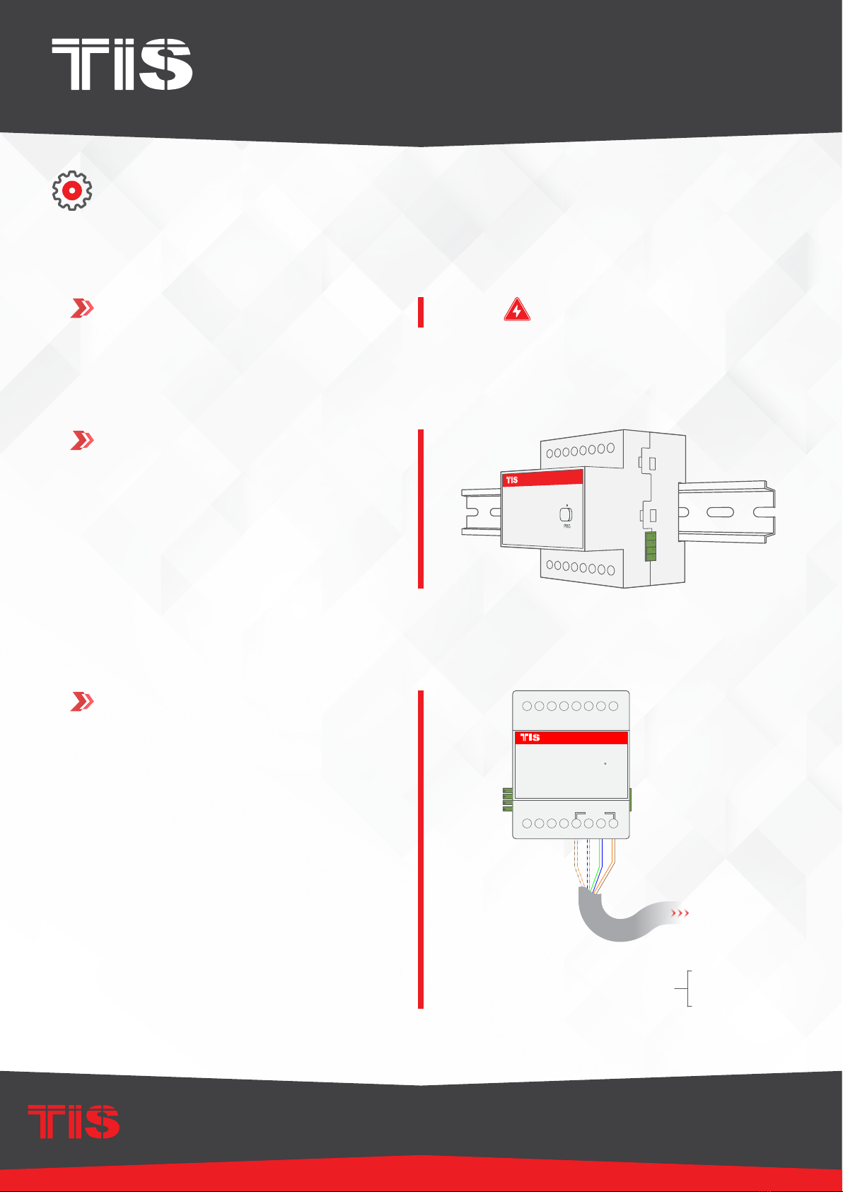
Mounting Din Rail Standard 35 mm Din rail
Wall mount screw holder on the back of the module
Dimensions Length × Width × Height 73mm × 76mm × 90mm
Housing
Materials ABS fire proof
Casing color Black Gray
IP rating IP 20
Temperature
range
Operation -30…60°C
Storage -20…60°C
Transport -30…75°C
Air humidity <80% non-condensing

INSTALLATION MANUAL
MODEL: P.S-24V-1.5A
TIS CONTROL LIMITED
RM 1502-p9 Easey CommBldg
253-261 Hennessy Rd Wanchai
Hong Kong
TEXAS INTELLIGENT SYSTEM LLC
SUITE# 610. 860 NORTH DOROTHY DR
RICHARDSON
TX 75081.USA
Copyright © 2020 TIS, All Rights Reserved
TIS Logo is a Registered Trademark of Texas Intelligent System LLC in the
United States of America. This company takes TIS Control Ltd. in other
countries. All of the Specifications are subject to change without notice.
www.tiscontrol.com
POWER SUPPLY 24V DC
Data Cable
Use screened stranded RS485 data cable
with four twisted pairs. Congure devices in
a “Daisy Chain.”
Do not cut or terminate live data cables.
Electrical Wires
The recommended wire size is 4…6mm2
for the Line, Neutral, and Output wires. The
installer should consider the total current
consumption when selecting the wires.
Warranty
There is a two-years warranty provided
by law. The hologram warranty seal and
product serial number are available on
each device.
Read Instructions
We recommend that you read this
Instruction Manual before installation.
Safety instructions
Electrical equipment should only be
installed and tted by electrically skilled
persons.
Failure to observe the instructions may
cause damage to the device and other
hazards.
These instructions are an integral part of
the product and must remain with the end
customer.
Programming
Advanced programming requires TIS
Device Search software. Advanced
software programming knowledge should
be obtained in the advanced training
courses.
Simple Installation
You can use either the DIN rail or xing
points to install this module.
Mounting Location
Install in a dry, well-ventilated location.
Controllers may emit some mechanical
noises. Consider this when deciding on a
mounting location.
INSTALLATION MANUAL
MODEL: P.S-24V-1.5A
TIS CONTROL LIMITED
RM 1502-p9 Easey CommBldg
253-261 Hennessy Rd Wanchai
Hong Kong
TEXAS INTELLIGENT SYSTEM LLC
SUITE# 610. 860 NORTH DOROTHY DR
RICHARDSON
TX 75081.USA
Copyright © 2020 TIS, All Rights Reserved
TIS Logo is a Registered Trademark of Texas Intelligent System LLC in the
United States of America. This company takes TIS Control Ltd. in other
countries. All of the Specifications are subject to change without notice.
www.tiscontrol.com
POWER SUPPLY 24V DC
Turn off the main electrical source before
installation.
1WARNING! HIGH VOLTAGE
INSTALLATION STEPS
Mount the device on DIN rails inside an
approved enclosure. The device can also
be installed using two mounting screw
holes.
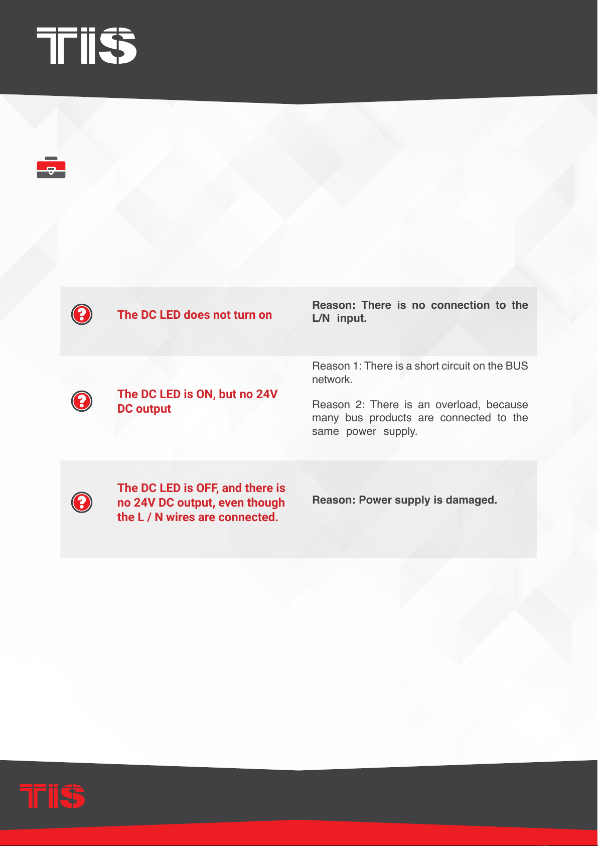
2
+24D+D-GND+24D+D-GND
Connect the RS485 data cable to the
TIS-BUS port following the product
connection diagrams.
It is necessary to loop the TIS-BUS cable
if the side bus-train terminal connects the
two DIN rail modules.
3
GND(white-orange)&(white-brown)
D-(white-green)&(white-blue)
D+(blue-green)
+24V(brown-orange)
Cat5econnection
P.S-24V-1.5A
DC
TIS-BUS
GND D+ +24V
D-
NL
To the TIS BUS Network
Cat5e

INSTALLATION MANUAL
MODEL: P.S-24V-1.5A
TIS CONTROL LIMITED
RM 1502-p9 Easey CommBldg
253-261 Hennessy Rd Wanchai
Hong Kong
TEXAS INTELLIGENT SYSTEM LLC
SUITE# 610. 860 NORTH DOROTHY DR
RICHARDSON
TX 75081.USA
Copyright © 2020 TIS, All Rights Reserved
TIS Logo is a Registered Trademark of Texas Intelligent System LLC in the
United States of America. This company takes TIS Control Ltd. in other
countries. All of the Specifications are subject to change without notice.
www.tiscontrol.com
POWER SUPPLY 24V DC
INSTALLATION STEPS
Connect the L, N, and PE to Live, Neutral,
and Earth cables, respectively. The
device input must have an appropriate
MCB to protect the module.
4
Connect To L
Connect To N
1.5 mm Electric Cable
1.5 mm Electric Cable
GND(white-orange)&(white-brown)
D-(white-green)&(white-blue)
D+(blue-green)
+24V(brown-orange)
Cat5econnection
O-OFF
I-ON
MCB P.S-24V-1.5A
DC
TIS-BUS
GND D+ +24V
D-
NL
To the TIS BUS Network
Cat5e
Turn on the power source. The module’s
LED should turn on and supply the BUS
network with 24V DC.
5
GND(white-orange)&(white-brown)
D-(white-green)&(white-blue)
D+(blue-green)
+24V(brown-orange)
Cat5econnection
P.S-24V-1.5A
DC
TIS-BUS
GND D+ +24V
D-
NL
To the TIS BUS Network
Cat5e
INSTALLATION MANUAL
MODEL: P.S-24V-1.5A
TIS CONTROL LIMITED
RM 1502-p9 Easey CommBldg
253-261 Hennessy Rd Wanchai
Hong Kong
TEXAS INTELLIGENT SYSTEM LLC
SUITE# 610. 860 NORTH DOROTHY DR
RICHARDSON
TX 75081.USA
Copyright © 2020 TIS, All Rights Reserved
TIS Logo is a Registered Trademark of Texas Intelligent System LLC in the
United States of America. This company takes TIS Control Ltd. in other
countries. All of the Specifications are subject to change without notice.
www.tiscontrol.com
POWER SUPPLY 24V DC
TROUBLESHOOTING
The DC LED does not turn on Reason: There is no connection to the
L/N input.
The DC LED is ON, but no 24V
DC output
Reason 1: There is a short circuit on the BUS
network.
Reason 2: There is an overload, because
many bus products are connected to the
same power supply.
The DC LED is OFF, and there is
no 24V DC output, even though
the L / N wires are connected.
Reason: Power supply is damaged.
Table of contents
Other TIS Power Supply manuals

Popular Power Supply manuals by other brands


TDK-Lambda
TDK-Lambda HWS 15A-150A/A Series instruction manual

Antec
Antec NEO ECO 620C user manual

Pico Communications
Pico Communications PICOPSU-90 Quick installation guide

Franke
Franke ZAQUA007 Installation and operating instructions

GMI
GMI D6011S instruction manual

TAKASAGO
TAKASAGO HX-S-G4 Series instruction manual