EPLAX Vero Power Trivolt PK60 Series Quick guide

119-014937K-12 EPLAX GmbH (Änderungen vorbehalten) Seite 1/4
Deutsch
Bedienungsanleitung und
Sicherheitshinweise
Bitte vor Inbetriebnahme lesen
Trivolt PK75/PK60
Primär getaktetes Einschubnetzteil
Das Trivolt PK75 / PK60 ist eine primärgetaktete Stromversorgung für 19”-Aufbausysteme nach
DIN 41494 in einer 3HE / 8TE Aluminium-Kassette. Die Kassette wird auf der rechten Seite geführt.
Die Führungshöhe beträgt 100 mm. Für den elektrischen Anschluß ist ein Steckverbinder nach DIN
41612 vom Typ H15 in Position 2 vorgesehen.
Vor Inbetriebnahme der Stromversorgung müssen die Federleisten sowie die Führungsschienen
(rechts um 180° gedreht) an der gewünschten Position im Baugruppenträger montiert werden.
Mechanische Details
Bezeichnung Ausgangsspannungen und max. Ströme Bestellcode
Trivolt PK75 5V/8A; +12...15V/2A; -12...-15V/1A 116-410018B
Trivolt PK60A 5V/8A; +12...15V/2A; -12...-15V/1A 116-010018J-xx *
Trivolt PK60B 5V/8A; +12...15V/2A; -12...-15V/1A 116-010101G-xx *
Trivolt PK60B PF 5V/8A; +12...15V/2A; -12...-15V/1A 116-010102D-xx *
Trivolt PK60A PF 5V/8A; +12...15V/2A; -12...-15V/1A 116-010103A-xx *
* xx = 60 oder höher
162,6
3HE=128,5 mm
8TE=40,24 mm
PSU
V3
V2
V1
110,8
EPLAX GmbH
Fritz-Thiele-Straße 12
D-28279 Bremen
www.eplax.de

Seite 2/4 (Änderungen vorbehalten) EPLAX GmbH 119-014937K-12
EMV-Richtlinie
2004/108/EG
EN61000-6-3
EN61000-6-2
+V1
+SENSE
GND V1
V2
GND V2 / V3
-SENSE
V3
PF Q
gegen GND V1
Imax 10mA
Netzeingang
und
Entstörung
Gleichrichter
AC/DC
L
N
PE
max.
30V
R
R = externer Pull-up Widerstand
5V
PF Q
5ms
Powerfail-Signal
DC/DC-Wandler
DC/DC-Wandler
Powerfail-Control
0
10
20
30
40
50
60
70
80
0 20 40 60 [°C]
Po [W]
Derating Kurve
Die Derating Kurve ist zu beachten.
Die Umgebungstemperaturen werden 3 mm
neben der rechten Gehäusewand gemessen.
Bedingungen: Derating beginnt bei 75W; 45°C,
endet bei 40W; 70°C.
Um Fehlfunktionen und Gefahren zu vermeiden, lesen Sie bitte vor Inbetriebnahme des Gerätes diese
Anleitung aufmerksam durch. Beim Betrieb des Gerätes sind die Sicherheitsbestimmungen
einzuhalten.
Diese Stromversorgung ist eine Komponente zur Weiterverarbeitung, der Anschluß darf nur von dazu
autorisiertem / qualifiziertem Fachpersonal erfolgen. Die Stromversorgung darf auf keinen Fall geöffnet
werden, da intern gefährliche Spannungen vorhanden sind. Nach Öffnen der Stromversorgung sind
jegliche Garantieansprüche gegenüber EPLAX GmbH erloschen.
Die Stromversorgung darf nur in eingebautem Zustand in einem 19”-Baugruppenträger nach
DIN41494 betrieben werden. Feldgebundene Störaussendung und Störfestigkeit sind einbauabhängig.
Für die Einhaltung der EMV-Richtlinie des Gesamtgerätes / -systems ist der Geräte- / Systemhersteller
verantwortlich.
Wichtige Informationen
Niederspannungsrichtlinie 2006/95/EG
EN60950-1
Prinzipschaltbild

119-014937K-12 EPLAX GmbH (Änderungen vorbehalten) Seite 3/4
Die Sensor-Anschlüsse dienen zur Kompensation
der Spannungsabfälle auf den Leitungen zwischen
dem Netzteil und der Last. Für die
Dimensionierung der Leitungen ist zu
berücksichtigen, daß ein max. Spannungsabfall
von insgesamt 0,5V zulässig ist.
Soll der Spannungsabfall kompensiert werden,
müssen die Sensor-Anschlüsse direkt an der Last
angeschlossen werden. Die Sensor- Leitungen
sollten miteinander verdrillt werden (siehe
Abbildung).
Wird keine Kompensation gewünscht, müssen die
Sensor-Anschlüsse direkt am Netzteil
angeschlossen werden (siehe Abbildung).
Ferner muß beachtet werden, daß der
Spannungsabfall auf den Leitungen in die
Leistungsbilanz des Netzteiles mit eingeht.
Achtung: Die Sensor-Anschlüsse dürfen auf
keinen Fall belastet werden, da sonst interne
Komponenten zerstört werden können!
Sensor-Betrieb
Elektrischer Anschluß
Anschlußbelegung der rückwärtigen
DIN-Stecker vom Typ: H15 nach DIN 41612
Pin Funktion
4 +V1
6 +V1
8 GND V1
10 GND V1
12 +SENSE
14 - SENSE
16 PF/
18 V2
20 GND V2/V3
22 V3
24 ——
26 ——
28 N
30 L
32 PE
Achtung:
Elektrischer Anschluß nur über eine
Federleiste H15 nach DIN 41612.
Pin 32 muß am Schutzleiter
angeschlossen sein.
Die SENSE-Anschlüsse müssen
angeschlossen sein, siehe Kapitel
Sensor-Betrieb.

Seite 4/4 (Änderungen vorbehalten) EPLAX GmbH 119-014937K-12
Technische Daten
Eingangsgrößen
Eingangsspannung: 115-230VAC (-18/+10%), 47...63Hz
Wirkungsgrad bei Vollast: typ. 79%
Power Factor: >0,6
Ausgangsgrößen V1 V2 V3
Ausgangsgleichspannung, einstellbar: 5V (4,5-5,5V) +11,8...+15,2V -11,8...-15,2V
Ausgangsgleichstrom: 8A 2A** 1A**
Ripple bei Vollast: 20mVss 5mVss 5mVss
** I2 und I3 gesamt max. 2,5A
Regelgrößen
Netzregelung (VIN min...max; 100% IOUT): 0,1% 0,02% 0,02%
Lastregelung (10...90% IOUT, statisch, typ): 0,1% 0,4% 0,4%
Regelzeit (10...90% IOUT, dynamisch): 0,4ms 20µs 20µs
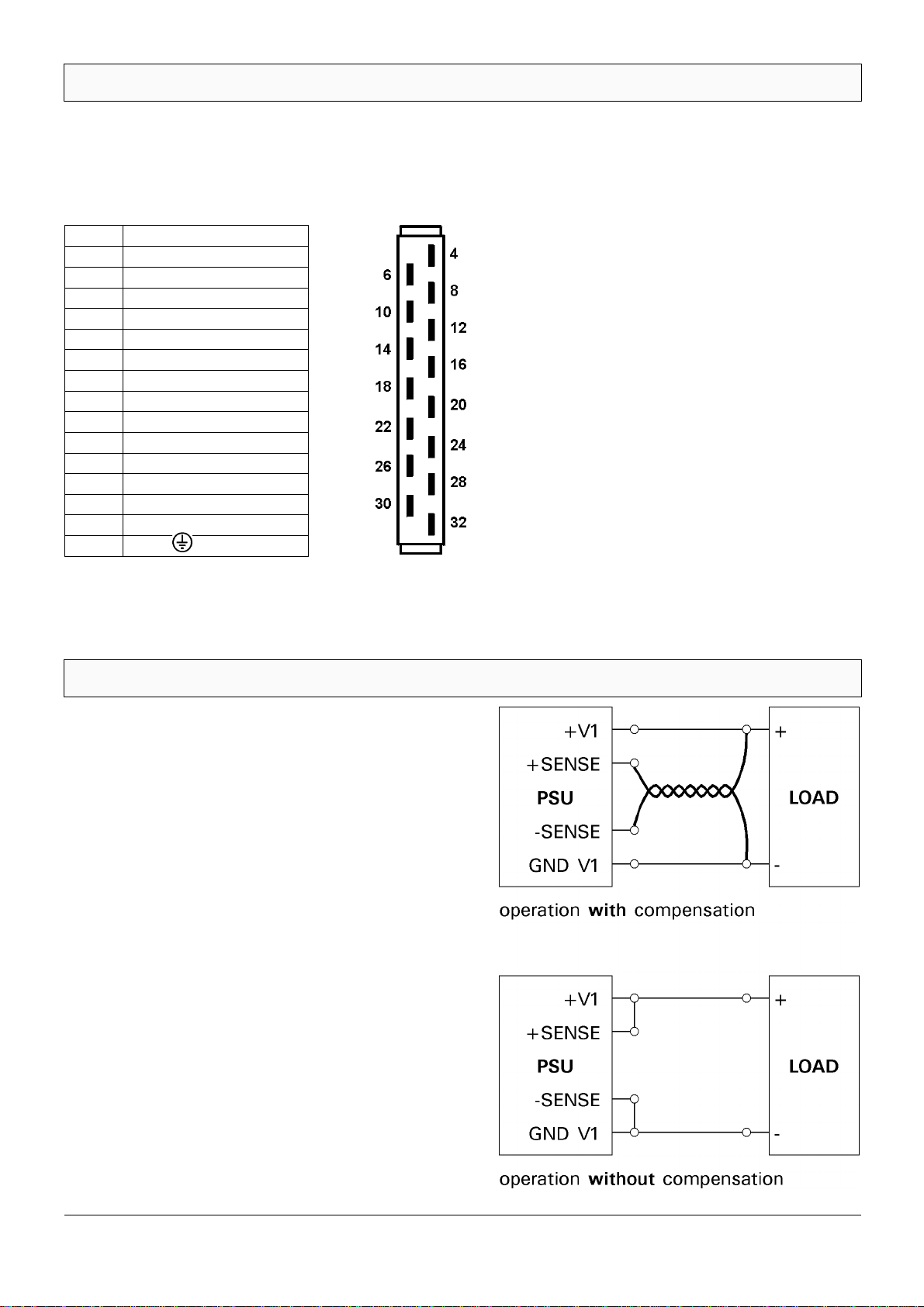
Spannungsausregelung mit Sense-Leistungen: 0,5V max. —— ——
Schutz- und Kontrolleinrichtungen
Begrenzung Ausgangsstrom: >8,4A >2,1A >2,1A
Begrenzung Ausgangsspannung (OVP): 5,85...6,25V fest —— ——
Kurzschlußschutz: ja ja ja
Einschalt- Stoßstrombegrenzung: durch NTC-Widerstand
Eingangsspannungsbegrenzung: durch VDR-Widerstand
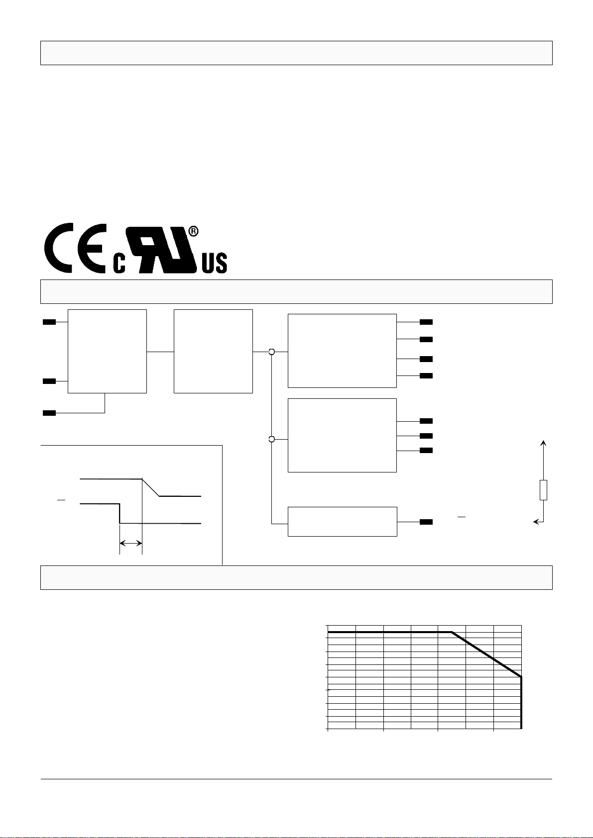
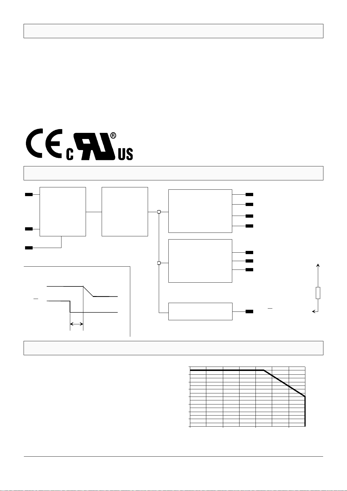
Netzausfallüberbrückung bei Nennlast: 30ms bei 230V; 10ms bei 115V
Powerfail-Signal (siehe Diagramm): 5ms bevor V1 < 4,8V
Sicherheit (LVD)
Isolationsfestigkeit: gem. EN60950-1 und gem. UL60950-1
Schutzklasse I nach VDE0100: Steckverbinder mit voreilendem Schutzkontakt
EMV (CE-Zeichen gemäß EMV-Richtlinie)
Störaussendung: EN55022/B (0,15-30MHz; 30-1000MHz)
Störstrahlung einbauabhängig
Störfestigkeit: Grenzwerte und Level gemäß EN 61000-6-2
ESD: EN 61000-4-2
HF-Einstrahlung: EN 61000-4-3
Burst: EN 61000-4-4
Surge: EN 61000-4-5
HF-Einströmung: EN 61000-4-6
Eingangsspannungseinbrüche: EN 61000-4-11
Betriebsgrößen
Umgebungstemperatur max.: 0...70° C
Derating: 1,4W/K ab 45° C., siehe Derating Kurve
Lagertemperatur -25° C ... +85° C
Relative Luftfeuchtigkeit: 5...95%, nicht kondensierend

119-014937K-12 EPLAX GmbH (reservation of changes) page 1/4
Trivolt PK75/PK60
Plug-In Power Supply
The TRIVOLT PK75 / PK60 is a plug-in power supply for 19” subrack systems according to
DIN 41494 in a 3U/8HP aluminium cassette. The power supply is guided on right hand side and the
guiding profile has to be turned 180 degree before mounting. The guiding height is 100mm.
The electrical connection is via an H15 connector according to DIN 41612 in position 2.
Before starting to use the power supply, the mating connector and the guides must be proper
installed and wired in the desired positions in the subrack.
Mechanical Details
English
Operating and Safety Instructions
Please read before use
EPLAX GmbH
Fritz-Thiele-Straße 12
D-28279 Bremen
www.eplax.co.uk
Model Output voltage Ordercode
Trivolt PK75 5V/8A; +12...15V/2A; -12...-15V/1A 116-410018B
Trivolt PK60A 5V/8A; +12...15V/2A; -12...-15V/1A 116-010018J-xx *
Trivolt PK60B 5V/8A; +12...15V/2A; -12...-15V/1A 116-010101G-xx *
Trivolt PK60B PF 5V/8A; +12...15V/2A; -12...-15V/1A 116-010102D-xx *
Trivolt PK60A PF 5V/8A; +12...15V/2A; -12...-15V/1A 116-010103A-xx *
* xx = 60 or higher

page 2/4 (reservation of changes) EPLAX GmbH 119-014937K-12
+V1
+SENSE
GND V1
V2
GND V2 / V3
-SENSE
V3
PF Q
against GND V1
Imax 10mA
Input
and
Filtering
Rectifier
AC/DC
L
N
PE
max.
30V
R
R = external Pull-up resistor
5V
PF Q
5ms
Powerfail-Signal
DC/DC-Converter
Powerfail-Control
DC/DC-Converter
0
10
20
30
40
50
60
70
80
0 20 40 60 [°C]
Po[W]
The power supply must be derated according
to the derating curve below. The ambient
temperature is measured 3mm beside the right
hand side of the cassette.
Terms: Derating starts at 75W; 45°C, ends at
40W; 70°C.
Important Information
Schematic circuit diagram
Derating Curve
Please read this instruction carefully before you start to use the unit in order to avoid any
malfunctions or hazards. During operation of the unit, all safety regulations must be observed.
This power supply is a component for further assembly and must only be connected by authorized/
qualified personnel. The unit must not be opened as dangerous voltage is inside. This would also
invalidate the warranty against EPLAX. There are no customer serviceable parts inside.
This power supply must be used only in 19” subracks according to DIN 41494 under final assembled
conditions. Field dependent EMI emission and EMI immunity are relevant to installation. The
equipment / system manufacturer is responsible that the complete equipment / system meets the
EMC-directive.
EMV-Directive
2004/108/EC
EN61000-6-3
EN61000-6-2
Low voltage Directive 2006/95/EC
EN60950-1

119-014937K-12 EPLAX GmbH (reservation of changes) page 3/4
Pin Function
4 +V1
6 +V1
8 GND V1
10 GND V1
12 +SENSE
14 - SENSE
16 PF/
18 V2
20 GND V2/V3
22 V3
24 ——
26 ——
28 N
30 L
32 PE
Sense-Operation
Electrical Connections / Pinning
Contact list of the connector at the rear side.
Type: H15 according to DIN 41612
The sense connections serve to compensate
voltages drop in the cables between the power
supply and the load. The dimension for the cables
must be selected considering that the max.
permissible total voltage drop is 0.5V.
If the voltage drop is to be compensated, the sense
lines must be connected directly to the load. The
sense lines should be twisted together. If no
compensation is desired, the sense connections
must be connected directly at the mating connector
(see diagrams).
Furthermore, remember that the voltage drop in the
wires also forms part of the power budget of the
Power supply.
Important: The sense lines must never be loaded
as this might destroy components !
Important:
Electrical connection must be to a
female H15 connector to DIN 41612.
PIN 32 (PE) has to be connected
according to saftey regulations.
The SENSE lines must be
connected in accordance with
chapter ”SENSE Operation”.

page 4/4 (reservation of changes) EPLAX GmbH 119-014937K-12
Technical Data
Input
AC input voltage: 115-230VAC (-18/+10%), 47...63Hz
Efficiency at full load: typ. 79%
Power Factor: >0.6
Output V1 V2 V3
Output voltage, adjustable: 5V (4.5-5.5V) +11.8...+15.2V -11.8...-15.2V
Output current: 8A 2A** 1A**
Ripple at full load: 20mVss 5mVss 5mVss
** I2 and I3 together max. 2.5A
Regulation
Line regulation (VIN min...max; 100% IOUT): 0.1% 0.02% 0.02%
Load regulation (10...90% IOUT, static, typ): 0.1% 0.4% 0.4%
Transient response (10...90% IOUT, dynamic): 0.4ms 20µs 20µs
Voltage stabilisation with sense: 0.5V max. —— ——
Protection and Control
Output current limit: >8.4A >2.1A >2.1A
Output voltage protection (OVP): 5.85...6.25V fixed —— ——
Short circuit protection: yes yes yes
Input surge current limitation: by NTC-Resistor
Input voltage limitation: by VDR-Resistor
Hold-up time (at full load): 30ms at 230V; 10ms at 115V
Powerfail-Signal (see Diagram): 5ms before V1 < 4.8V
Safety (CE-Mark according LVD)
Dielectric strenght according: EN60950 and UL60950-1
Protection Class I to VDE0100: Mating connector with leading earth pin
EMI (CE-Mark according EMC-Directive)
Emission: EN55022/B (0.15-30MHz; 30-1000MHz)
Radiated emission depends on application
Immunity: Level according EN 61000-6-2
ESD: EN 61000-4-2
HF-Field: EN 61000-4-3
Burst: EN 61000-4-4
Surge: EN 61000-4-5
HF-Injection: EN 61000-4-6
Line voltage drops: EN 61000-4-11
Environmental
Operating Temperature: 0...70° C
Derating: 1,4W/K from 45° C., see diagram
Storage Temperature -25° C ... +85° C
Relative Humidity: 5...95%, none condensing
This manual suits for next models
5
Table of contents
Languages:
Popular Power Supply manuals by other brands

Altronix
Altronix AL600X220 Series installation guide

Potter
Potter PSN-106 Installation, operation and instruction manual

Toshiba
Toshiba RAS-S10CX Brochure & specs

Innovative Energies
Innovative Energies SR100A Series user manual

Altronix
Altronix AL176UL installation instructions

Eaton
Eaton Ellipse 375 Installation and user manual