manuals.online logo
Brands
  1. Home
  2. •
  3. Brands
  4. •
  5. TDK-Lambda
  6. •
  7. Power Supply
  8. •
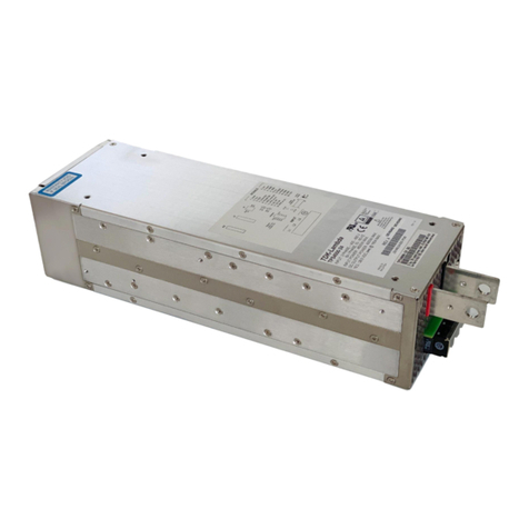
  9. TDK-Lambda HWS 15A-150A/A Series User manual

TDK-Lambda HWS 15A-150A/A Series User manual

This manual suits for next models

10

Other TDK-Lambda Power Supply manuals

TDK-Lambda Z+ series User manual

TDK-Lambda

TDK-Lambda Z+ series User manual

TDK-Lambda GENESYS GEN 2400W Series User manual

TDK-Lambda

TDK-Lambda GENESYS GEN 2400W Series User manual

TDK-Lambda CUS800M User manual

TDK-Lambda

TDK-Lambda CUS800M User manual

TDK-Lambda HWS 1500 Series User manual

TDK-Lambda

TDK-Lambda HWS 1500 Series User manual

TDK-Lambda HFE2500 Series User manual

TDK-Lambda

TDK-Lambda HFE2500 Series User manual

TDK-Lambda ELC50 Series User manual

TDK-Lambda

TDK-Lambda ELC50 Series User manual

TDK-Lambda LS 200 Series User manual

TDK-Lambda

TDK-Lambda LS 200 Series User manual

TDK-Lambda GENESYS 1500W User manual

TDK-Lambda

TDK-Lambda GENESYS 1500W User manual

TDK-Lambda DRB120 Series User manual

TDK-Lambda

TDK-Lambda DRB120 Series User manual

TDK-Lambda CUS60M User manual

TDK-Lambda

TDK-Lambda CUS60M User manual

TDK-Lambda 500A User manual

TDK-Lambda

TDK-Lambda 500A User manual

TDK-Lambda HWS300 Series User manual

TDK-Lambda

TDK-Lambda HWS300 Series User manual

TDK-Lambda CPFE1000F SERIES User manual

TDK-Lambda

TDK-Lambda CPFE1000F SERIES User manual

TDK-Lambda DDA Series User manual

TDK-Lambda

TDK-Lambda DDA Series User manual

TDK-Lambda ZBM-AC Series User manual

TDK-Lambda

TDK-Lambda ZBM-AC Series User manual

TDK-Lambda G10-500 Setup guide

TDK-Lambda

TDK-Lambda G10-500 Setup guide

TDK-Lambda CPFE500F-28 User manual

TDK-Lambda

TDK-Lambda CPFE500F-28 User manual

TDK-Lambda Genesys GEN8-300 User manual

TDK-Lambda

TDK-Lambda Genesys GEN8-300 User manual

TDK-Lambda GXE600 Series Use and care manual

TDK-Lambda

TDK-Lambda GXE600 Series Use and care manual

TDK-Lambda Genesys Series User manual

TDK-Lambda

TDK-Lambda Genesys Series User manual

TDK-Lambda CME Series User manual

TDK-Lambda

TDK-Lambda CME Series User manual

TDK-Lambda 203 User manual

TDK-Lambda

TDK-Lambda 203 User manual

TDK-Lambda HFE2500-S1U User manual

TDK-Lambda

TDK-Lambda HFE2500-S1U User manual

TDK-Lambda LS25 Series User manual

TDK-Lambda

TDK-Lambda LS25 Series User manual

Popular Power Supply manuals by other brands

Videx 520MR Installation instruction

Videx

Videx 520MR Installation instruction

Poppstar 1008821 Instructions for use

Poppstar

Poppstar 1008821 Instructions for use

Calira EVS 17/07-DS/IU operating instructions

Calira

Calira EVS 17/07-DS/IU operating instructions

Monacor PS-12CCD instruction manual

Monacor

Monacor PS-12CCD instruction manual

VOLTIMA MagicBox 15 Installation and operating instructions

VOLTIMA

VOLTIMA MagicBox 15 Installation and operating instructions

Miller Auto Deltaweld 452 owner's manual

Miller

Miller Auto Deltaweld 452 owner's manual

BCP PUOUBK How to install

BCP

BCP PUOUBK How to install

HC 2210 manual

HC

HC 2210 manual

Agilent Technologies 6032A Service manual

Agilent Technologies

Agilent Technologies 6032A Service manual

Radial Engineering SB-48UB user guide

Radial Engineering

Radial Engineering SB-48UB user guide

Puls CT5.241 installation manual

Puls

Puls CT5.241 installation manual

OCZ ZX1250W Technical specifications

OCZ

OCZ ZX1250W Technical specifications

iseg ECH 238 manual

iseg

iseg ECH 238 manual

Agilent Technologies 6631B Service manual

Agilent Technologies

Agilent Technologies 6631B Service manual

Power XXL A Series instruction manual

Power

Power XXL A Series instruction manual

HP 6200B Operating and service manual

HP

HP 6200B Operating and service manual

Epson Stylus Scan 2500 Product information sheet

Epson

Epson Stylus Scan 2500 Product information sheet

Pulsar GREEN POWER CCTV PoE POE044816 manual

Pulsar

Pulsar GREEN POWER CCTV PoE POE044816 manual

manuals.online logo
manuals.online logoBrands
  • About & Mission
  • Contact us
  • Privacy Policy
  • Terms and Conditions

Copyright 2025 Manuals.Online. All Rights Reserved.

HWS 15A-150A/A Series
UL508 Instruction Manual
BEFORE USING THE POWER SUPPLY UNIT
Pay attention to all warnings and cautions before using the unit. Incorrect usage could lead to an electrical shock,
damage to the unit or a fire hazard.
CAUTION
・Minor electric shock, fire, or Product failure may occasionally occur.
Do not disassemble, modify, or repair the Product or touch the interior of the Product.
・Minor burns may occasionally occur.
Do not touch the Product while power is being supplied or immediately after power is turned OFF.
・Minor electric shock, fire, or Product failure may occasionally occur. Do not allow any pieces of
metal or conductors or any clippings or cuttings resulting from installation work to enter the Product.
・Minor injury due to electric shock may occasionally occur.
Do not touch the terminals while power is being supplied. Always close the terminal cover after wiring.
NOTICE:
Installing/Storage Environment
1. Store the product with ambient temperature –30 to +85 oC, and relative humidity 10 to 95% (No Dewdrop).
2. Never operate the unit under over current or shorted conditions for 30 seconds or more and out of Input
Voltage Range in specification which could result in damage or insulation failure or smoking or burning.
3. Confirm connections to input/output terminals are correct as indicated in the instruction manual.
4. Use the product where the relative humidity is 30 to 90% (No Dewdrop).
5. Avoid places where the product is subjected to direct sunlight..
6. Avoid places where the products are subjected to penetration of liquid, foreign substance, or corrosive gas.
7. Avoid places subject to shock or vibration. A device such as a contact breaker may be a vibration source.
Set the Power Supply as far as possible from sources of shock or vibration.
8. If the Power Supply is used in an area with excessive electronic noise, be sure to separate the
Power Supply as far as possible from the noise sources.
9. When the product is used under the circumstance or environment below, ensure adherence to limitations of the ratings
and functions. Also take countermeasures for safety precautions such as fail-safe installations.
a). Under the circumstances or environment which are not described in the instruction manual.
b). For nuclear power control, railway, aircraft, vehicle, incinerator, medical equipment, entertainment equipment,
safety device etc…
10. For applications where death or serious property damage is possible and extensive safety precautions are re
quired.
11. This power supply has possibility that hazardous voltage may occur in output terminal depending on failure mode.
The output of these products must be protected in the end use equipment to maintain SELV.
Note
: Use Environment
For use in pollution Degree 2 environment.
TDK-Lambda
HWS15A-150A/A Series
UL508 INSTRUCTION MANUAL
A255
-
04
-
81/A
-
H
・Warning Symbols
1
TDK-Lambda
HWS15A-150A/A Series
UL508 INSTRUCTION MANUAL
1. Model name identification method
HWS 15A – 5 / □
Option (*1 )
Rated Output Voltage
Output Power type
Series Name
2. Terminal Explanation
HWS15A, HWS30A, HWS50A
① +V : + Output terminal
② –V : – Output terminal
③ FG : Frame Ground
④ L : Input terminal Live line (Fuse in line)
⑤ N : Input terminal Neutral line
⑥ Output voltage adjustment trimmer
⑦ Output monitoring indicator (Green LED)
HWS50A/RA
⑧ –R : Remote ON/OFF control
⑨ +R : Remote ON/OFF control
HWS80A, HWS100A, HWS150A
① +V : + Output terminal
② –V : – Output terminal
③ FG : Frame Ground
④ L : Input terminal Live line(Fuse in line)
⑤ N : Input terminal Neutral line
⑥ +S : + Remote sensing terminal
⑦ –S : – Remote sensing terminal
⑧ Output voltage adjustment trimmer
⑨ Output monitoring indicator (Green LED)
HWS80A/RA, HWS100A/RA, HWS150A/RA
⑩ –R : Remote ON/OFF control
⑪ +R : Remote ON/OFF control
(*1)
/A :With cover type
/RA :Remote ON/OFF control with cover
/ADIN :DIN rail mountable
(Only cover type of 5-48V)
/HDA:High resistance against dustenvironment
with cover type.
(Refer to the specifications for details.)
6
7
1
2
3
4
5
9
8
9
8
10
11
3
2
4
5
1
6
7
2
TDK-Lambda
HWS15A-150A/A Series
UL508 INSTRUCTION MANUAL
3. Mounting Method
1) This is convection cooling type power supply. In the consideration for the heat radiation and safety. Please take a
distance more than 15mm between the power supply and the peripheral parts. When lining up multiple units, please
make sure to place them 15mm or more apart from each other.
2) The maximum allowable penetration of mounting screws is 6mm.
3) Recommended torque for mounting screw
HWS15A-150A (M3 screw) : 0.49 N×m( 5.0 kgf×cm )
4. Wiring Method
1) Input line shall be separated and twisted to improve noise sensitivity.
2) The sensing lines shall be twisted and separated from the output lines.
3) Use all lines as thick and short as possible to make lower impedance.
4) Noise can be eliminated by attaching a capacitor to the load terminals.
5) For safety and EMI considerations, connect the FG terminal of HWS15A-150A to mounting set ground terminal.
6) The recommended wire type :
MODEL
Recommende
d
Wire
Recommended torque
Recommended
crimp
-
type terminal
D
(MAX)
t
(MAX)
Mounting
piecs
(MAX)
HWS15A-50A AWG14-22 All terminal M3.5 Screws 1.6N・m (16.3kgf・cm, 14.2lb・in) 6.8mm 0.8mm 2 piece
HWS80A,100A
AWG12-22 Output terminal M3.5 Screws 1.6N・m (16.3kgf・cm, 14.2lb・in)
8.1mm 1.0mm 1 piece
0.8mm 2 piece
AWG14-22 Other terminal M3.5 Screws 1.6N・m (16.3kgf・cm, 14.2lb・in) 6.8mm 0.8mm 2 piece
HWS150A AWG10-22 Output terminal M3.5 Screws 1.6N・m (16.3kgf・cm, 14.2lb・in)
8.1mm 1.0mm 1 piece
0.8mm 2 piece
AWG14-22 Other terminal M3.5 Screws 1.6N・m (16.3kgf・cm, 14.2lb・in)
6.8mm 0.8mm 2 piece
Note 1 : When using separate loads, use of two pcs. of 0.8mm thick crimp-type terminal is recommended.
Note 2 : Select the wire diameter in consideration of the rated current and the current during OCP operation.
For recommended diameter, refer to wire maker recommended allowable current and voltage drop.
Especially, for 3V or 5V models, output current is large. Thick diameter wire is recommended.
Note 3 : Use wires rating at least 90℃(CSA) / 75℃(UL) and copper conductor only.
Note 4 : Use crimp-type terminal for connection to terminal.
5. External Over Current Protection
The following types of fuses that 1.5 times or less the rated current should be connected to the
output of the power supply. And also select to wire diameter according to Note 2 of
"4. Wiring Method".
cUL Listed or UL Listed with CSA Certificated fuse Class : C, CA, CB, CC, G, H, J, K, L, R, T, CF
15mm or more
Provide punching, etc. to allow air to pass.
15mm or more
Air flow
Sheet Metal
3
TDK-Lambda
HWS15A-150A/A Series
UL508 INSTRUCTION MANUAL
6. Output Derating according to the Mounting Directions
Recommend standard mounting is method ( A ). Method ( B ), ( C ) and ( D ) are also possible. Refer to the derating
below. Please do not use installation method ( E ), where the PCB will be on the topside and heat will be trapped inside
the unit. Load(%) such as below derating curve indicates output power.
■Mounting Directions
■Output Derating
Standard Mounting ( A ) (Cover type)
HWS15A , 80A HWS30A
HWS50A HWS100A , 150A
0
20
40
60
80
100
120
-10 0 10 20 30 40 50 60 70 80
Ambient temperature (℃)
Load (%)
0
20
40
60
80
100
120
-10 0 10 20 30 40 50 60 70 80
Ambient temperature (℃)
Load (%)
0
20
40
60
80
100
120
-10 0 10 20 30 40 50 60 70 80
Ambient temperature (℃)
Load (%)
0
20
40
60
80
100
120
-10 0 10 20 30 40 50 60 70 80
Ambient temperature (℃)
Load (%)
Input voltage range
85Vac≦Vin<90Vac
(*) /HDA : 71℃
(*)
(*) /HDA : 71℃
(*)
(*) /HDA : 71℃
(*)