Tiso Tiso-19 Installation instructions

Tiso-19 Tracker
Hardware Guide

CONTENTS
1 - Electrical Specifications
1.1 Electrical Overview
1.2 Hardware Overview
1.3. Wiring Overview
2 - Wiring and Connections
2.1 Electrical Connections List
2.1.2 “X” Relay
2.1.3 External Sounder
2.1.4 Static Alarm
2.1.4.2 Static Notifications
2.1.4.3 Set Alarm Zero
2.1.5 Spare IO's
2.1.6 External Alarm In
2.1.7 Power Supply
2.1.7.1 Minimum wiring with ignition monitoring
2.1.7.2 Minimum wiring without ignition monitoring
Note
The information provided in this document is believed to be accurate and reliable. However no responsibility is
assumed for its use, nor misuse, nor any infringement on any other rights of third parties. This document is subject to change
without notice.

1 - Device Specifications
1.1 Electrical Overview
Typical Max
Supply Voltage 12 40
Current 62mA 2A(Peak)
Table 1
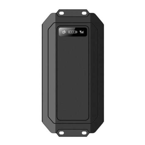
1.2 Hardware Overview
Box size
86mm long
55mm wide
26mm height
Material – Aluminum / Plastic

1.3 Wiring Overview

2 - Electrical Connections
2.1 Electrical Connections List
Power Connector
Pin Colour Description Use
1 RED +V Poitive
2 BLACK GND Ground
3 YELLOW Ignition Ignition Monitoring
4 BROWN Fuel Fuel Monitoring
IO Connector
Pin Colour Description Use
1 BLUE Auxiliary Ground Additional Ground
2 PURPLE RS232 RX RS232 Data In
3 RED Auxiliary supply (+ve) Auxiliary supply
4 PURPLE RS232 TX RS232 Data Out
5 YELLOW Normally Open External
Switch Please see Static Alarm section
6 BLACK Static Relay GND Static Relay Ground
7 WHITE Normally Closed Remote
Switch Please see Static Alarm section
8 WHITE Static Relay Com Static Relay Common
9 YELLOW Set Alarm Zero Please see Static Alarm section
10 WHITE Static Relay NO Normally Open Static Relay
11 GREY Spare IO1 Can be connected to external IO
12 BROWN X.Relay NO Normally Open Relay
13 GREY Spare IO2 Can be connected to external IO
14 BROWN X.Relay Com Used in conjunction with pin 12 or 14
15 GREY Ext Alarm in (IO3) Can be connected to vehicle alarm aux
output
16 BROWN X.Relay NC Normally Closed Relay, used in conjunction
with pin 14, Can be used for disabling
vehicle

2.1.2 “X” Relay
This is controlled via SMS or GPRS messages
:W,X,1 Selects NO
:W,X,0 Selects NC (by default the relay is in this state)
(Max load on relay contacts = 1AMP resistive)
It is possible to use this relay to disable a vehicle.
To interrupt the fuel pump, disconnect the supply to the pump and connect it to the tracker on
Pin 13. Then connect Pin 16 of the tracker to the positive on the fuel pump.
To disable the vehicle, send the :W,X,1 command to change the relay to the Normally Open
(NO) position.
2.1.3 External Sounder
(Max load on relay contacts = 1AMP resistive)
This can be wired in using the static relay.
The External sounder pin is used to connect devices to ground. The external device has to be
connected to positive.

2.1.4 Static Alarm
The Static Alarm is designed as a simple multi function alarm monitor.
N.B. For correct Static Alarm functionality the Normally closed Switch must be connected
to ground, otherwise the unit will always be in a static condition.
In the above example both the normally closed and the normally open switch are connected to
switches to ground, this is the simplest configuration.
2.1.4.2 Static Notifications
The device monitors alarm events via the normally open and normally closed switches.
If there is a static event then the user is sent a SMS text and the GPRS Server is updated with
the static event
2.1.4.3 Set Alarm Zero
This is used to bypass the Static Alarm circuitry. By default there is a 12 second delay in the
Static alarm trigger, in that time if the set alarm zero pin is held at +ve then the static condition
will be bypassed.
This is useful if the owner of the vehicle gets into thier car and turns the Ignition on within 12
seconds.

2.1.5 Spare IO's
Pins 11 and 13 (also 15 if unused for external alarm input) on the tracker can be used for
monitoring the status of external devices such as switches or sensors. These devices have to
operate at 12V.
For example:
Battery monitoring, or door switch.
2.1.6 External Alarm In
On most vehicle alarms there is an external alarm output. Connect this to Pin 15. If the
vehicle alarm is triggered the owner is notified via text message and the information is also
sent to the control server to indicate an alarm event.

2.1.7 Power Supply
For correct operation the tracker needs to be connected to the vehicles battery supply (either
directly or through existing wiring e.g. back of stereo)
It is recommended that the +ve supply of the ignition is wired through a 3Amp fuse to protect
the vehicle wiring.
2.1.7.1 Minimum wiring with ignition monitoring
2.1.7.2 Minimum wiring without ignition monitoring
Table of contents

