Titan Attachments FMSS6 User manual

SKID STEER FINISH MOWER
FMSS6, FMSS5
191539, 191540
Operator’s Manual
Read the Operator’s Manual entirely. When you see this
symbol, the subsequent instructions and warnings are
serious follow without exception. Your life and the lives
of others depend on it!

2
IMPORTANT SAFETY INFORMATION
THESE ARE STANDARD PRACTICES THAT MAY NOT APPLY TO THE PRODUCTS
DESCRIBED IN THIS MANUAL.
SAFETY AT ALL TIMES
Thoroughly read and understand the instructions given in this manual before operation. Refer
to the “Safety Label” section, read all instructions noted on them. Do not allow anyone to
operate this attachment who has not fully read and comprehended this manual and who has
not been properly trained in the safe operation of the mower.
•Operator should be familiar with all functions of the unit.
•Operate mower from the loader only.
•Make sure all guards and shields are in place and secured before operating mower.
•Do not leave the loader or mower unattended with engine running.
•Removing from a moving loader could cause serious injury or death.
•Watch out for wires, trees, etc., when raising mower.
•Make sure all persons are clear of working area.
•Do not carry passengers on mower at any time.
LOOK FOR THE SAFETY ALERT SYMBOL
The SAFETY ALERT SYMBOL indicates there is a potential hazard to personal safety involved
and extra safety precaution must be taken. When you see this symbol, be alert and carefully
read the message that follows it. In addition to design and configuration of the mower, hazard
control, and accident prevention are dependent upon the awareness, concern, prudence, and
proper training of personnel involved in the operation, transport, maintenance, and storage of
the mower.
BE AWARE OF SAFETY ALERT WORDS
A Signal word designates a degree or level of hazard seriousness, signal words are:
DANGER: Indicates imminently hazardous practices. A situation that, if not avoided, will result
in death or severe injury. The signal word is limited to the most extreme situation, typically for
machine components that, for functional purposes, cannot be guarded.
WARNING: Indicates a potentially hazardous situation that, if not avoided, could result in death
or severe injury, and includes hazards that are exposed when guards remove. Use warnings to
alert against unsafe practices.
CAUTION: Indicates a potentially hazardous situation that may result in minor or moderate
injury if not avoided. It may also be used to alert against unsafe practices.

3
FOR YOUR PROTECTION
Thoroughly read and understand the “Safety Label” section, read all instructions noted on them.
SHUTDOWN AND STORAGE
•Lower mower to the ground, remove from the loader. Put loader in park, turn off engine,
and remove the key.
•Detach and store mower in an area where children normally do not play.
PREPARE FOR EMERGENCIES
•Be prepared if a fire starts.
•Keep a first aid kit and fire extinguisher handy.
•Keep emergency numbers for doctor, ambulance, hospital, and fire department near the
phone.
WEAR PROTECTIVE EQUIPMENT
•Wear protective clothing and equipment appropriate for the job. Avoid loose-fitting
clothing.
•Prolonged exposure to loud noise can cause hearing impairment or hearing loss. Wear
suitable hearing protection such as earmuffs or earplugs.
•Operating equipment safety requires the full attention of the operator. Avoid wearing
radio headphones while operating machinery.
AVOID HIGH-PRESSURE FLUIDS HAZARD
•Escaping fluid under pressure can penetrate the skin causing severe injury.
•Avoid the hazard by relieving pressure before disconnecting hydraulic lines or performing
work on the system.
•Ensure all hydraulic fluid connections are tight and all hydraulic hoses and lines are in
good condition before applying pressure to the system.
•Use a piece of paper or cardboard, NOT BODY PARTS, to check for suspected leaks.
•Wear protective gloves and safety glasses or goggles when working with hydraulic
systems.
•If an accident occurs, see a doctor immediately. Remember, any fluid injected into the skin
must be treated within a few hours, or gangrene may result.

4
SAFETY LABELS
Your Skid Steer Finish Mower comes equipped with all safety labels in place. They were
designed to help you to safety operate your mower. Read and follow their directions.

5
INTRODUCTION
APPLICATION
The finish mower is designed to cut short grass and lawns and matched the loader.
SECTION 1: ASSEMBLY AND SET-UP
PACKING DESCRIPTION
•Remove and check
•Remove the packing, check goods without defect and omission
Figure 1-1: Your New Mower as It Is Shipped to You
Figure 1-2: The Mower and Accessory in Package

6
2. PACKING LIST
THE DETAILED PACKING LIST OF THE MOWER AND ACCESSORY AS THE FOLLOWING
TABLE 1.
Table 1-1: Packing List of The Mower and Accessory
THE DETAILED DESCRIPTION OF WHEEL BRACKET-ASSEMBLY
Figure 1-3: Wheel Bracket Assembly
Table 1-2: Wheel Bracket Assembly List

7
THE DETAILED DESCRIPTION WHEEL FRAME AND FITTNGS
Figure 1-4: Wheel Frame and Fittings
Table 1-3: Wheel Frame and Fittings List

8
ASSEMBLY
The assembly instruction will guide you to finish the final assembly of your new mower easily.
1. TOOL REQUIRED
•½” Ratchet wrench with 13mm, 24mm sleeves
•17-19 Spanner.
2. TORQUE APPLICATION
Refer to bolt torque in Section 8 Appendix.
3. ASSEMBLY
Cut all zip ties and disassemble shipping crate.
Step 1: Installing wheel frame and fittings Remove the packaging of wheel frame and
fittings. Assemble 2pcs of wheel frames on the mower deck body. Parts: 4pcs of Bolts
M16x95, 8pcs of plain washers 16, 4pcs of spring washers 16, 4pcs of nuts M16, 2pcs of
bolt M8x20, 2pcs of spring washers 8 and 2pcs of large plain washers 8. Tighten nut and
bolt completely.
WARNING
RAISE the mower deck to ensure that the wheel frame can be installed with enough
height.
Figure 1-5: Installing Wheel Frame and Fittings

9
Step 2: Installing wheel bracket assembly and fittings. Remove the packaging of wheel bracket
assembly and fittings. Assemble wheel bracket assemblies on wheel frame as well as spacers.
Through the combination of spacers with different height to get the mowing height you need.
Parts: 4pcs of wheel bracket assemblies. Use safety lock pin to hold wheel bracket.
WARNING
Make sure all wheel height adjustments are same,
otherwise it will lead to uneven mowing.
Figure 1-6: Installing Wheel Bracket and Fittings
Step 3: Double check the mower is complete.
Figure 1-7: Skid Steer Finish Mower Status
WARNING
FILL THE GEARBOX WITH PROPER AMOUNT OF SAE 90 GEAR OIL BEFORE YOUR FIRST
OPERATION.
Pay attention to adjust the rotation direction of the hydraulic motor to make the blade
edge.
10
MOWER INSTALLATION
NOTE: The illustrations and instructions provided explain how to install a bucket
attachment on to a loader. Follow these same instructions if you are installing different
attachments such as a grapple, tiller, mower, etc. The attachment mounting frame for
the attachment has a top flange that is designed to receive the top edge of the Bob-Tach
and the lower part of the frame is designed to receive the Bob-Tach wedges.
IMPORTANT: Always inspect the loader’s Bob-Tach and the attachment mounting frame
before installation.
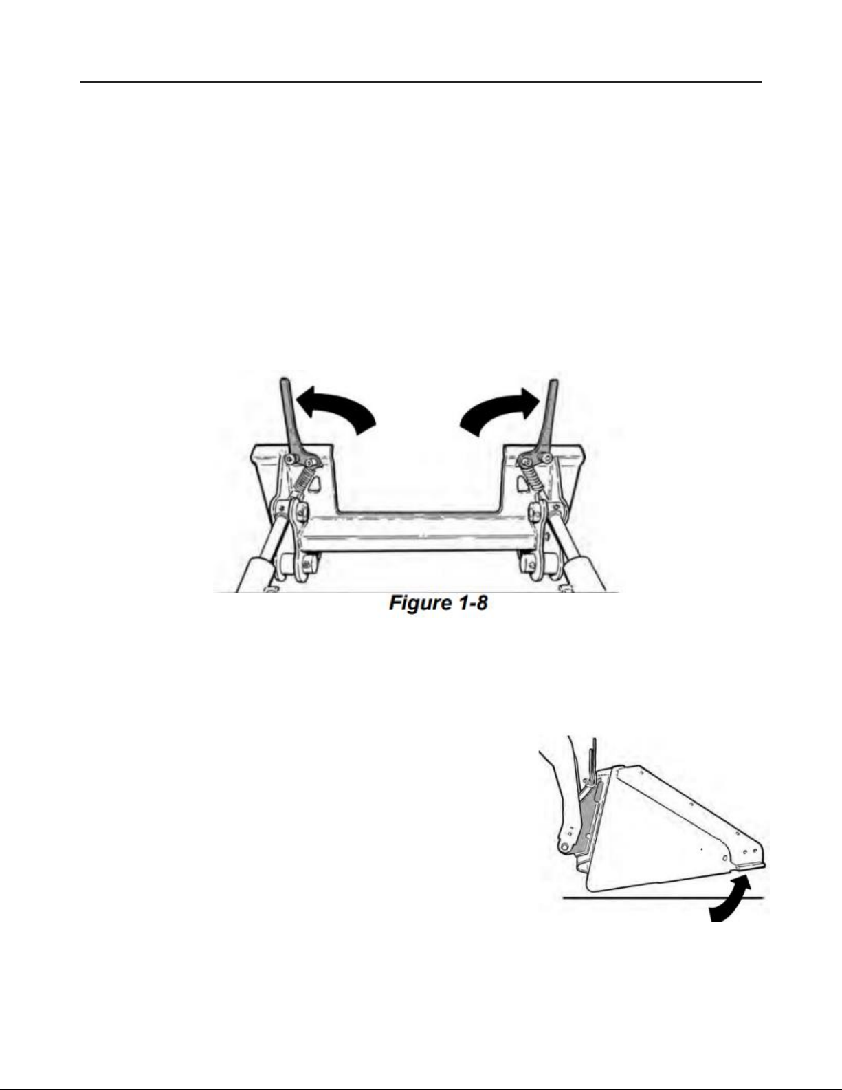
a. Pull the Bob-Tech levers up until they are fully raised (wedges fully raised). Refer to
Figure 1-8.
b. Enter the loader, start the engine, press the PRESS TO OPERATE LOADER button and
release the parking brake.
c. Lower the lift arms and tilt the Bob-Tach forward.
d. Drive the loader slowly forward until the top edge of the Bob-Tach is completely under
the top flange of the attachment mounting frame. Refer to Figure 1-9.
NOTE: Be sure the Bob-Tach levers do not hit the attachment.
e. Tilt the Bob-Tach backward until the attachment is
slightly off the ground. This will cause the attachment
mounting frame to fit up against the front of the Bob-
Tach. Refer to Figure 1-10.
FIGURE 1-1
NOTE: When leaving the operator’s seat to install an attachment, tilt the attachment until it is
slightly off the ground.
11
f. Stop the engine and exit the loader.
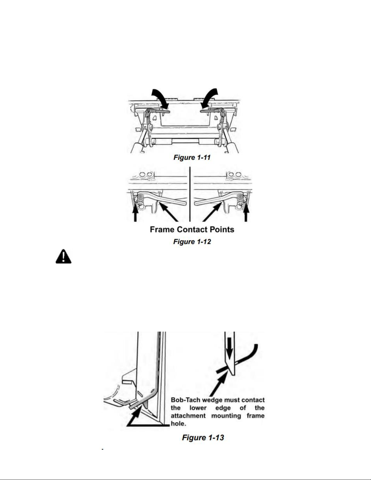
g. Push down on the Bob-Tach levers until they are fully engaged in the locked position
(wedges fully extended through the attachment mounting frame holes). Refer to Figure
1-11.
Both levers must contact the frame as shown when locked. Refer to Figure 1-12.
WARNING
AVOID INJURY OR DEATH The Bob-Tach wedges must extend through the holes in the
attachment mounting frame. Levers must be full down and locked. Failure to secure
wedges can allow attachment to come off.
h. The wedges must extend through the holes in the attachment mounting frame, securely
fastening the attachment to the Bob-Tach. Refer to Figure 1-13.

12
MOWER REMOVAL
NOTE: In muddy conditions or to prevent the attachment from freezing to the ground, put the
attachment on planks or blocks before removing the attachment from the loader.
a. Lower the lift arms and put the attachment flat on the ground. Lower or close the
hydraulic equipment.
b. Stop the engine and release auxiliary hydraulic pressure.
c. Exit the loader.
d. Disconnect auxiliary hydraulic hoses.
e. Pull the Bob-Tach levers up until they are fully raised (wedges fully raised). Refer to
Figure 1-14.
WARNING
Bob-Tach levers have spring tension. Hold lever tightly and release slowly. Failure to obey
warning can cause injury.
f. Enter the loader.
g. Start the engine, press the
PRESS TO OPERATE LOADER
button and release the parking
brake. 13
h. Tilt the Bob-Tach forward and drive the loader backward, away from the attachment.
Refer to Figure 1-15.
13
SECTION 2: DAILY INSPECTION
ATTACHMENT MOUNT FRAME
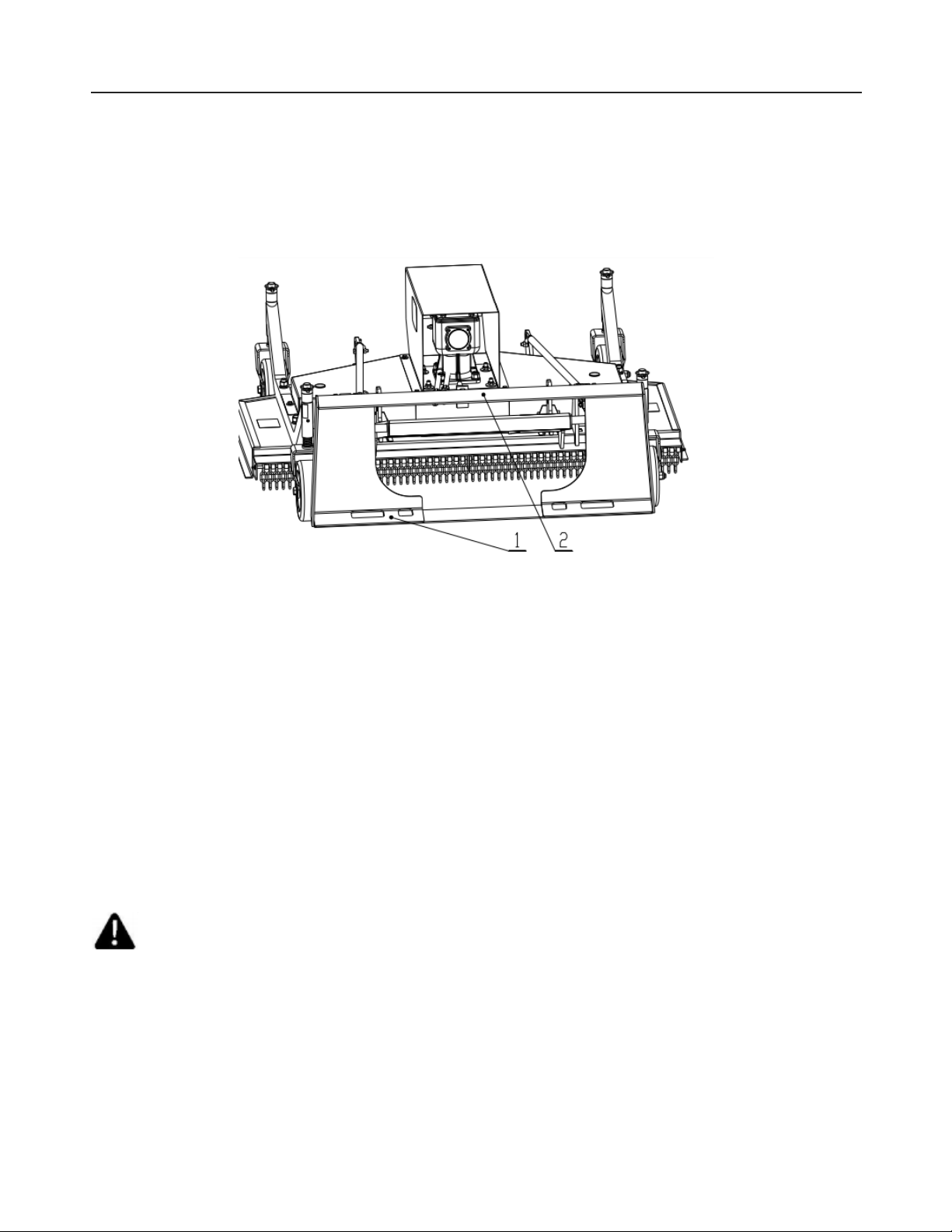
Inspect the Bob-Tach wedge mounts (item1), mounting flange (item2) and all welds on the
attachment mount for wear or damage each time the attachment is removed from the loader.
Refer to Figure 2-1.
Figure 2-1
MOWER INSPECTION
Check the following items every 25 hours of operation:
•Check blade for cracks or damage. Replace if necessary.
•Check blade mounting hardware for proper torque 350N.m (260 ft-lb).
•Check deck and shield. Repair if damaged or replace if necessary.
•Check for damaged or missing decals. Replace if necessary.
•Check for damaged or leaking hydraulic hoses or fittings. Replace if necessary.
•Clean debris, leaves, grass and flammable material from deck area and pulley covers.
•Lubricate all 7 grease points.
•Check blade belts for condition and wear. Adjust or replace as necessary.
•Check for loose, damaged, or missing nuts and bolts. Retighten or replace if necessary.
WARNING
AVOID INJURY OR DEATH
Never work on a machine with the attachment raised unless secured by an approved
support device. Failure to use an approved support device can cause the lift arms, boom,
or attachment to fall and cause serious injury or death. Diesel fuel or hydraulic fluid
under pressure can penetrate skin or eyes, causing serious injury or death.
Fluid leaks under pressure may not be visible. Use a piece of carboard or wood to find
leaks. Do not use your bare hand. Wear safety goggles. If fluid enters skin or eyes, get
immediate medical attention from a physician familiar with this injury.

14
SECTION 3: OPERATING INSTRUCTIONS
MOWING PROCEDURE
The ground condition and the type of grass being cut will determine the best cutting procedure
and ground speed. The mower is designed to cut short grass and lawns.
NOTE: When operating the mower, damage to the turf may occur when sharp turns are
made.
DANGER
THROWN OBJECTS WILL CAUSE SERIOUS INJURY OR DEATH
•Clear mowing area of debris.
•Never operate mower in vicinity of other persons. Objects can be thrown more
than several hundred feet.
•Keep all shields installed, Repair or replace if damaged.
•Check blades and mounting hardware. Replace if damaged. Never weld or modify.
a. Clear the cutting area of objects which might be picked up and thrown.
b. Adjust the mower deck to the desired cutting height.
c. Enter the loader.
d. Start the engine and release the parking brake.
e. Carry the mower low to the ground when driving.
f. With engine at low RPM, lower the lift arm fully, until the mower caster wheels are flat on
the ground.
g. Tilt the Bob-Tach forward, the chains (item 1) should be slack. Adjust lift arms so the side
bar (Item 2) is centered in the slide channels of the mower. Refer to Figure 3-1.
FIGURE 3-1

15
NOTE: The chains prevent the mower from scalping the lawn when mowing rough or hilly
lawns.
h. Engage the auxiliary hydraulics.
Note: The auxiliary hydraulics must be activated prior to attachment operation.
i. Increase engine speed to full rpm and drive the loader forward into the work area.
j. Start the blade rotation.
DANGER
ROTATING BLADES WILL CAUSE SERIOUS INJURY OR DEATH
•Never put hands, feet, or objects into or under mower when engine is running.
•Keep bystanders away.
•No riders.
•Stop engine before servicing.
LIFTING THE ATTACHMENT
Hang the hooks of the chain slings into the 4 holes on the machine deck as shown in the Figure
3-2. Position the chain slings in a location which will balance the mower while lifting.
Figure 3-2
NOTE: Use chain slings with 4 hooks that are in good condition and of adequate size to
lift the attachment.

16
SECTION 4: ADJUSTMENTS
Belt Adjustment
1. Tool Required
½” Ratchet wrench with 13mm, 19mm sleeves
22-24 Spanner
2. Torque Application
Refer to bolt torque in Section 8 Appendix.
a. Remove mower from the loader.
b. Disconnect item 1 from the mower main body.
c. Remove item 3, item 8, item 9.
d. Loosen item 11 and then tighten the inner item 10 to adjust belt tension.
e. Tighten the outer item10 to lock the gearbox position.
f. Retighten item 11.
g. Reinstall item 3, item 8, item 9 and retighten item 4, item7.
h. Reconnect item 1 with the mower main body.
Figure 4-1 Belt Adjustment
Item1 –chain & rope fittings 2pcs
Item2 –chains 2pcs
Item3 –pulley cover L 1pcs
Item4 –Bolt M8x20 2pcs
Item5 –spring washer 8 6pcs
Item6 –Large plain washer 8 6pcs
Item7 –Bolt M8x25 4pcs
Item8 –Motor cover 1pcs
Item9 –Pulley cover R 1pcs
Item10 –Hex. Nut M16 2pcs
Item11 –Bolt M12x40 4pcs
Item12 –Locknut M12 4pcs
Item13 –Large plain washer 12 4pcs
Item14 –Rubber plug φ91.3
17
CUTTING HEIGHT ADJUSTMENT
WARNING
ATTACHMENT ROLLAWAY CAN CAUSE SERIOUS INJURY OR DEATH.
•Always park attachment on flat level ground.
•Block attachment before removing from machine.
a. Remove mower from the loader.
b. Lifting the attachment from the ground to ensure that all wheel brackets can be
removed easily after release the safety lock pin.
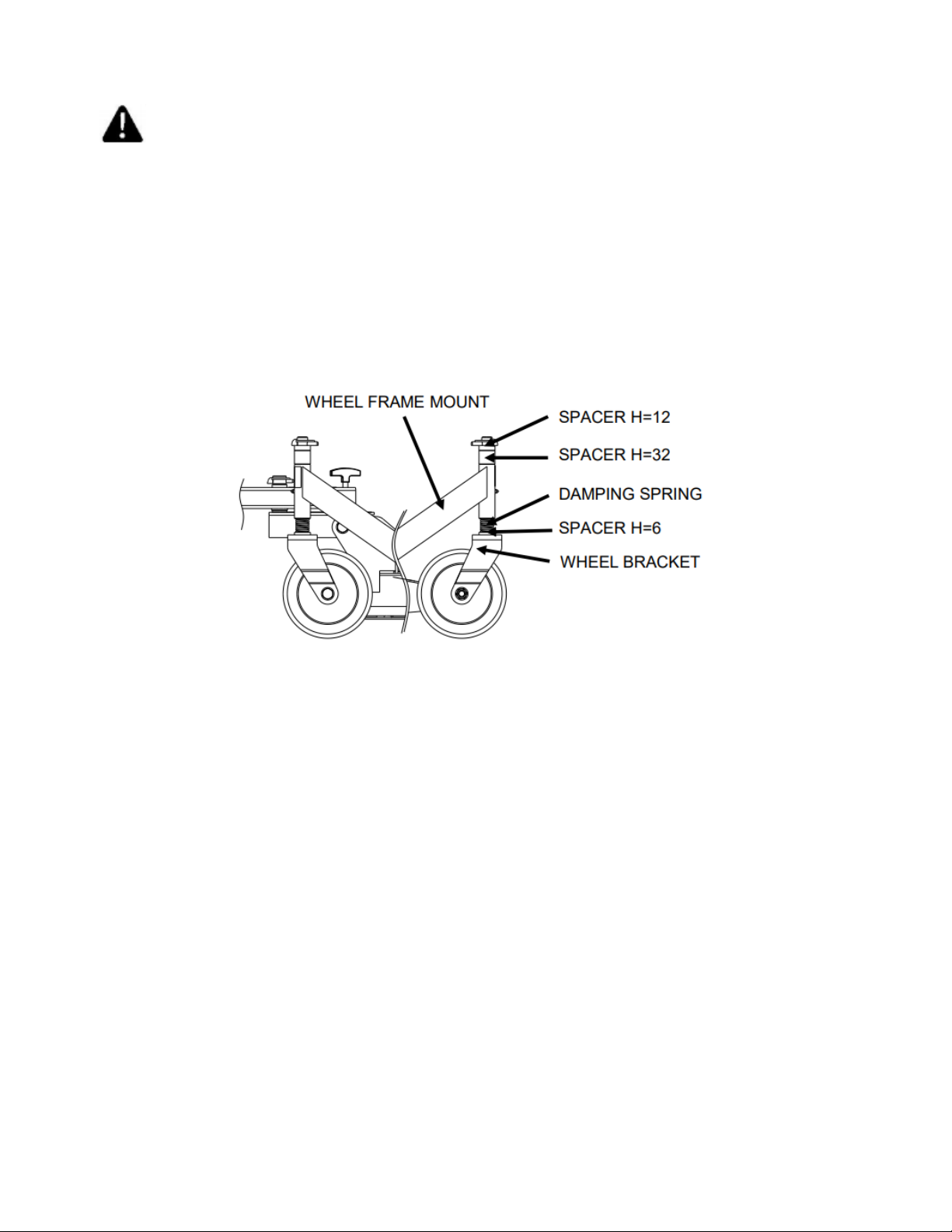
c. Through the combination of spacers with different height to get the mowing height you
need. See Figure 4-2 Cutting Height Adjustment
Figure 4-2 Cutting Height Adjustment
NOTE: Make sure all wheel height adjustments are same, otherwise it will lead to uneven
mowing. Adjust the gap distance between wheel frame mount and wheel yoke to get
your mowing height. Cutting height is between 0.4 to 3.35 inches.

18
SECTION 5: MAINTENANCE AND LUBRICATION
Proper servicing and adjustment are the key to the long life of any farm attachment. With
careful and systematic inspection, you can avoid costly maintenance, time, and repair.
CLEANING THE MOWER
WARNING AVOID INJURY OR DEATH
Wear safety glasses to prevent eye injury when any of the following conditions exist: .
When fluids are under pressure.
•Flying debris or loose material is present.
•Engine is running.
•Tools are being used.
a. Remove mower from the loader.
b. Lifting the attachment from the ground to keep enough working space.
c. Use water or air pressure to clean debris from the bottom of the mower deck. Use care
when removing any objects that are wrapped around blades and blade shafts.
d. Remove motor cover and belt covers.
e. Use water or air pressure to clean debris from the area under the cover.
f. Reinstall motor cover and belt cover.
BELT REPLACEMENT
a. Follow step a to c.
b. Loosen item 10, item 11 and push the gearbox forward to release the belts.
c. Remove item 14 and pressure lubricator under the gearbox mount bracket.
d. Replace old belts with new.
e. Reinstall pressure lubricator and item 14.
f. Tighten the inner item10 and then tighten the outer item 10 to lock the gearbox position.
g. Retighten item 11.
h. Reinstall item 3, item 8, item 9 and retighten item 4, item 7.
i. Reconnect item 1 with the mower main body.
BLADE REPLACEMENT AND SHARPENING
a. Follow step a to b.
b. Follow step b to c.
c. Check and remove old blades.
d. When the cutting edge of the blades become dull, remove the blades, and have a
sharpening service sharpen at a 31°angle and balance the blades. Refer to Figure 5-1.
e. Replace the blades when they reach a width of 47.5mm.

19
Always replace all three blades with blades that are equal in weight to prevent vibration. Use
only genuine TITAN replacement blades. If any vibration in the mower is felt, the blades must
be balanced or replaced. f. Follow step h to i. Refer to Belt Replacement on page20.
FIGURE 5-1 BLADE
STORAGE
At the end of the working season or when the mower will not be used for a long period. It is
good practice to clean off any dirt or grease that may have accumulated on the mower and any
of moving parts.
•Thoroughly clean the attachment.
•Lubricate the attachment.
•Inspect the Bob-Tach wedge mounts, mounting flange and all welds on the attachment
for wear and damage.
•Check for loose hardware, missing guards, or damaged parts.
•Replace worn or damaged parts.
•Check for damaged or missing decals. Replace if necessary.
•Place the attachment in a dry protected shelter.
•Place the attachment flat on the ground.
NOTE: In muddy conditions or to prevent the attachment form freezing to the ground, put
the attachment from freezing to the ground, put the attachment on planks or blocks
before removing the attachment from the machine.

20
LUBRICATION
Lubrication Points
Check oil level in gearbox by removing the cap located on top. Oil should be level with middle
side of plug hole. Remove top cap and side plug, add oil until it flows from middle side plug
hole.
This manual suits for next models
3
Table of contents
Other Titan Attachments Lawn Mower manuals


 owner's manual")


