Titan Attachments AT100 User manual

ATV TOW- BEHIND FLAIL MOWERS
AT100, AT120
191530,191498
Operator’s Manual
Read the Operator’s Manual entirely. When you see this
symbol, the subsequent instructions and warnings are
serious follow without exception. Your life and the lives
of others depend on it!

2
INTRODUCTION
Thank you for purchasing a TITAN BRANDS product. Please read this Manual carefully and
familiarize yourself and other persons that will be using the machine with its contents, to
ensure the optimum performance and working life of your machine.
The Tow-Behind Flail Mower hooks up to the ball receiver on any ATV or UTV. It is equipped with
a Briggs and Stratton 420cc XR Professional Series Engine with an electric start and 13.5 Gross
Horsepower. By using this flail mower with an ATV or UTV, you can cut through tough terrain
that is covered in heavy weeds with ease.
PLEASE READ THE FOLLOWING PAGES CAREFULLY BEFORE USING YOUR MACHINE
TITAN BRANDS machines are guarded for your protection, but you must always observe certain
basic precautions. Machines are potentially dangerous, and ALL OPERATORS MUST read this
manual and are aware of all safety precautions.
1. NEVER attempt any adjustment unless the machine is COMPLETELY at a standstill.
2. NEVER attempt to clear any obstructions around the mower unless the machine is
COMPLETELY at a standstill.
3. NEVER remove belt guards unless the machine is COMPLETELY at a standstill.
4. NEVER remove safety guards which are provided for your protection.
5. NEVER operate the mower with people behind, keep safe distance of minimum 60 feet.
6. Regularly inspect the BLADES AND FIXING BOLTS.
7. Replace blades IMMEDIATELYif any signs of fracture or excess wear becomes apparent.
Serious damage may result from using your mower with an unbalanced rotor. When
replacing blades, always fit new mounting bolts and nuts to ensure that the rotor is
balanced and running smoothly.
8. Engine oil is 10W-30 grade SJ, and regular gasoline is recommended for the Briggs
and Stratton 420cc XR Professional Series Engine. The operator can find oil
capacity and specification from the engine manufacturer’s instructions. Always
check the oil level before starting the mower.
IMPORTANT ATV SAFETY WARNINGS
BODY PROTECTION
•Remember that when riding on an ATV the only form of protection that you have is what
you wear. ALWAYS wear a helmet, eye protection and suitable robust clothing.
•Never operate an ATV or attachments while under the influence of alcohol or non-
prescription drugs.
•Contact your doctor before operation of an ATV or attachments while under the
influence of any prescription drugs.
ATV MANUAL
Before coupling any implement to your ATV refer to your ATV handbook.
STABILITY
•When using equipment coupled to an ATV it is very important to remember that the
handling characteristics of your ATV will change dramatically, whether the additional

3
load is placed on the front or rear rack or trailed on the towing ball hitch.
WEIGHT CAPACITY
•Always ensure that the implement or attachment that you are coupling to the ATV is
within the ATV’s drawbar loading or weight carrying capacity. Refer to the ATV
manufacturer’s handbook to obtain information on the specific capacities.
•It is most important that you know the weight of your load, especially when on slopes or
hillsides.
•As a guide, on level ground with an unbraked implement, the weight of the implement
should be approximately no more than twice the unladen weight of the ATV. This should
be reduced on sloping, uneven, or rough ground.
TOWING
•Never tow loads larger or heavier than recommended for your ATV. (See ATV handbook).
•Never tow or turn across a slope.
•Never tow down a steep slope with a large or heavy load.
•When towing heavy loads there is a significant risk of jack-knifing or overturning.
ROUGH TERRAIN
•Always take care when operating implements on rough terrain or uneven ground.
•Take special care when operating on slippery surfaces especially hill sides or slopes.
•Take extra care when towing on hillsides, slopes, or rough terrain.
OPERATING ON ROADS
•Implements are not designed for travelling distances on roads but when crossing or
going short road distances always travel slowly
•Make sure that your equipment complies with Road Vehicle Lighting Regulations.
•Ensure that you have the correct insurance cover and comply with all relevant laws.
PASSENGERS
•Never carry passengers on any kind of implement or attachment, especially children.
MAINTENANCE
•Service your ATV and attachments as per the manufacturer’s handbook. Regular
servicing of your ATV will ensure that it will steer, stop and handle to its best ability and
your attachment will operate as safely and effectively as possible. Regular servicing helps
ensure the longest possible working life for your equipment.
EQUIPMENT SAFETY INSPECTION
Check tire pressure, incorrect tire pressure can seriously affect the handling of your ATV. (See
Operators handbook).
Maintain your equipment regularly to keep it in safe working order.
ROUTE / RISK ASSESSMENT
•Assess and plan the route that you intend to travel to avoid any type of hazards i.e.,
rocks, boulders, ditches, hidden fences or wire, potholes, low hanging branches or any
other type of hazard.

4
•Where possible stay with a routine route to avoid hazards.
•The risk may change in wet or wintery conditions, avoid slopes where possible.
USE YOUR MOWER
It is recommended that every machine is inspected after one hour of operation to check
that all nuts, bolts, screws, or any other types of fixings are tight. Further inspections
should be carried out at regular intervals thereafter.
OPERATION
1. Manual Clutch - Always start the engine with the clutch disengaged. IMPORTANT - To
commence cutting, engage the clutch slowly!
2. Suitable forward speed will be determined by the amount, type, and condition of
material to be cut. In very difficult conditions, better results will be obtained by making
two passes, and adjusting cutting height accordingly.
3. Cutting height is adjusted by turning the adjustment handle in the relevant direction.
BELT ADJUSTMENT
1. Remove the belt cover.
2. Loosen clamping bolt.
3. Tighten belts using adjusting screw and lock off.
4. Retighten clamp bolt.
5. Replace the belt cover
MAINTENANCE IMPORTANT! Check all fastening sets (bolts and nuts) are tight after the
first hour of operation.
LUBRICATION
•DAILY (8-10 working hours
•Grease main rotor bearings.
•Grease roller bearings.
•Grease wheel bearings.
FLAIL BLADES
•The condition of the flail blades should be inspected daily. Damaged flail blades cause
imbalance in the rotor and in turn, will cause serious damage to the mower.
•If the mower begins to vibrate, stop work immediately and investigate. Almost certainly
the cause will be damaged flail blades, or foreign objects around the flail rotor.
FLAIL BLADES - CHANGING
•When fitting new flail blades, unhitch the mower from the tractor/ATV and lift the mower
up enough to access the blades, (preferably with a hoist or mechanical lifting
equipment). Remove the damaged flail blades and replace.
•It is important that the rotor remains balanced. Always fit new bolts and nuts when
replacing the flails and preferably fit a full set. If only one or two flails are being replaced,
they should be fitted opposite to each other on the rotor, to keep the rotor balanced.

5
TROUBLESHOOTING

6
COVER ASSEMBLY PARTS DIAGRAM / EXPLODED VIEW

7
COVER ASSEMBLY PARTS LIST
REF
PART NUMBER
DESCRIPTION
QTY
1
GM-8610
TRAILER COVER 50*50
1
2
MF120.01.101
BIG FLAT MAT Φ13
4
3
MF120.01.102
SQUARE TUBE
1
4 GB/T5782-2000 BOLT M12X60 8
5
GB/T97.1-2002
FLAT MAT 12
13
6 GB/T889.1-2000 NUT M12 13
7
MF120.01.013
TURNTABLE WELDMENT
1
8
GB/T5782-2000
BOLT M12X90
1
9 MF120.01.103 U HOOP 68 2
10
MF120.01.012
PIPE WELDMENT
1
11 MF120.01.109 RUBBER PLATEN 1
12 GB/T5782-2000 BOLT M6X25 6
13 MF120.01.108 RUBBER SHEET 1
14 MF120.01.015 SUPPORTING FRAME 1
15 FEL300.114 PIN Φ2R 1
16 GB/T882-2000 B PIN 8X40 1
17 MF120.01.011 THE COVER WELDMENT 1
18 GB/T12-2000 BOLT M6X20 2
19 MF120.01.014 BAFFLE WELDMENT 1
20 GB/T889.1-2000 NUT M6 8
21 GB/T97.1-2002 FLAT MAT 6 8
22 GB/T5782-2000 BOLT M8X20 10
23
GB/T97.1-2002
FLAT MAT 8
10
24 GB/T889.1-2000 NUT M8 10
25 MF120.01.107 GRASS BOARD 1
26 MF120.01.105 STRAW BOARD 1
27 MF120.01.106 CONE GASKET 1
28 GB/T70.3-2000 SCREW M10X30 1
29 GB/T96.1-2002 BIG FLAT MAT 10 1
30 JB/T7382 NUT M10 1
31 MF120.01.104 PLASTIC CAP 2

8
TRANSMISSION ASSEMBLY PARTS DIAGRAM / EXPLODED VIEW

9
TRANSMISSION ASSEMBLY PARTS LIST
REF PART NUMBER DESCRIPTION QTY
1
MF120.02.107
LOCATING ROUND STEEL
1
2
MF120.02.013
BELT PULLEY COVER
1
3
GB/T1154-97
STRAP SPB1393
2
4 MF120.02.108 TIGHTENING WHEEL 1
5
MF120.02.102
PRESSING SLEEVE
1
6
L65BH
120XSPBX2-25.4A CENTRIFUGAL CLUTCH 1
7
GB/T894.2-1986
CIRCLIP 20
1
8
GB/T276-1994
BEARING 6204-2RS
2
9
MF120.02.014
PULL RING WELDMENT
1
10
GB/T6170-2000
NUT M10
1
11 GB/T5783-2000 BOLT M10X80 1
12 MF120.02.015 ARM TIGHTENING 1
13 GB/T6170-2000 NUT M12 14
14 GB/T93-2002 SPRING WASHER 12 4
15 GB/T97.1-2002 FLAT MAT 12 4
16 JF420A MANUAL GASOLINE ENGINE 1
17 MF120.02.103 ENGINE BASE 1
18 GB/T5782-2000 BOLT M8X200 2
19 MF120.02.110 BATTERY PRESSURE PLATE 1
20 GB/T889.1-2000 NUT M8 2
21 MF120.02.109 BATTERY COVER 1
22 V-36A BATTERY 36A 1
23
GB/T97.1-2002
FLAT MAT 1
5
24 GB/T70.3-2000 SCREW M12X35 4
25 MF120.01.106 CONE GASKET 4
26 GB/T5782-2000 BOLT M12X45 4
27 GB/T97.1-2002 FLAT MAT 12 8
28 GB/T889.1-2000 NUT M12 8
29 MF120.02.106 COVER PLATE 1
30 GB/T7180-1995 BEARING UCFU207 2
31 MF120.02.012 DUST COVER 1
32 MF120.02.011 CUTTER SHAFT 1
33 GB/T889.1-2000 NUT M10 47
34 MF120.02.101 BLADE 80
35 GB/T96.1-2002 BIG FLAT MAT 10 127
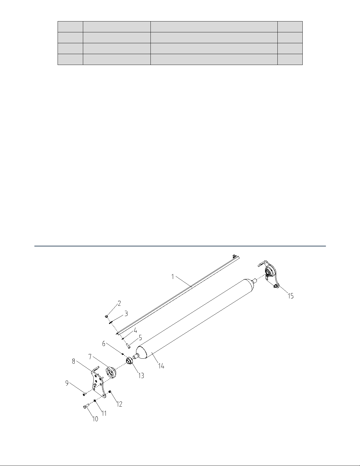
10
36 GB/T5782-2000 BOLT M10X50 44
37 GB/T5782-2000 BOLT M12X50 4
38 MF120.02.104 PULLEY 1
39 JB/T7934-00 EXPANSION 35X60 1
ROLLER ASSEMBLY PARTS DIAGRAM / EXPLODED VIEW

11
ROLLER ASSEMBLY PARTS LIST
REF PART NUMBER DESCRIPTION QTY
1
MF120.03.102
SCRAPER
1
2 GB/T889.1-2000 NUT M10 2
3
GB/T96.1-2002
BIG FLAT MAT 10
2
4
GB/T97.1-2002
FLAT MAT 10
2
5
GB/T5782-2000
BOLT M10X30
2
6
GB/T1152-89
OIL CUP
2
7
EFGC125.107
BEARING
2
8
MF120.03.101
SUPPORTING FOR ROLLER (R)
1
9 GB/T70.3-2000 SCREW M8X25 8
10
GB/T5782-2000
BOLT M12X35
4
11 GB/T97.1-2002 FLAT MAT 12 4
12 GB/T889.1-2000 NUT M12 4
13 GB/T3882-2000 BEARING UC205 2
14 MF120.03.011 ROLLER WELDMENT 1
15
MF120.03.103
SUPPORTING FOR ROLLER (L)
1
12
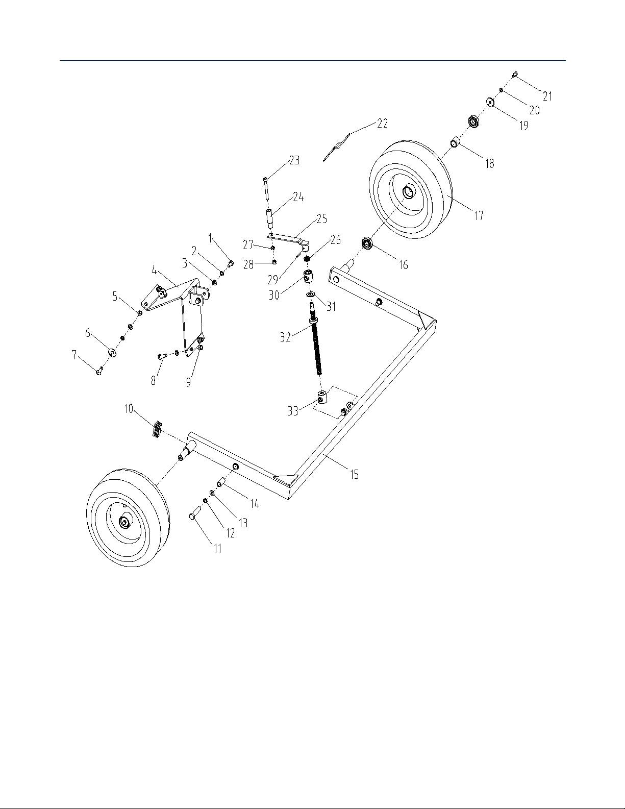
TIRE RACK ASSEMBLY PARTS DIAGRAM / EXPLODED VIEW

13
TIRE RACK ASSEMBLY PARTS LIST
REF PART NUMBER DESCRIPTION QTY
1
GB/T5782-2000
BOLT M12X20
4
2
GB/T93-2002
SPRING WASHER 12
6
3
GB/T97.1-2002
FLAT MAT 12
8
4 MF120.04.012 ROCKER BASE 1
5
GB/T6170-2000
NUT M12
2
6 MF120.01.106 CONE GASKET 2
7
GB/T70.3-2000
SCREW M12X35
2
8
GB/T5782-2000
BOLT M12X35
2
9 GB/T889.1-2000 NUT M12 2
10
MF120.04.103
PLASTIC COVER
2
11 GB/T5782-2000 BOLT M16X70 2
12 GB/T93-2002 SPRING WASHER 16 2
13 GB/T97.1-2002 FLAT MAT 16 2
14 MF120.04.104 BUSHING 2
15 MF120.04.011 BRACKET WELDMENT 1
16 GB/T276- BEARING 6205-2RS 4
17 4P/TL16*6.5-8 TIRE 16*6.5-8 2
18 MF120.04.101 BEARING SPACER 2
19 MF120.04.102 BIG FLAT MAT Φ11 2
20 GB/T93-2002 SPRING WASHER 10 2
21 GB/T5782-2000 BOLT M10X20 2
22 MF120.04.105 LOCK CATCH 1
23
GB/T70.1-2000
BOLT M10*90
1
24 MF120.04.107 PLASTIC HANDLE 1
25 MF120.04.016 ROCKER ARM WELDMENT 1
26 GB/T301 BEARING 51102 1
27 GB/T6170-2000 NUT M10 1
28 GB/T889.1-2000 NUT M10 1
29 GB/T879.2-2000 ELASTIC PIN 2
30 MF120.04.015 TURN SLEEVE WELDMENT 1
31 MF120.04.106 COPPER PAD 1
32 MF120.04.013 SCREW SLEEVE 1
33 MF120.04.014 ROCKER WELDMENT 1
34 MF120.04.108 PLASTIC COVER 2
14
ACKNOWLEDGEMENT OF RISK AND RELEASE OF LIABILITY
The use of any equipment, including this one, involves the potential risk of injury. Apart from any
warranty claim that might be presented for a claimed defect in material or workmanship of the product,
you accept and assume full responsibility for any and all injuries, damages (both economic and non-
economic), and losses of any type, which may occur, and you fully and forever release and discharge
Titan, its insurers, employees, officers, directors, associates, and agents from any and all claims,
demands, damages, rights of action, or causes of action, present or future, whether the same be known
or unknown, anticipated, or unanticipated, resulting from or arising out of the use of said equipment.
This equipment must be used with care by capable and competent individuals under supervision, if
necessary.
WARNING
Do not overfill! Mower should be level
when checking oil in gear box.
some activities might be able to cause
electric shock
Sharp objects may be involved.
Use protective cover during maintenance.
TITAN LIMITED WARRANTY: TERMS, EXCLUSIONS AND LIMITATIONS OF REMEDIES
This product comes with a one (1) year limited warranty that can be found at
www.palletforks.com/warranty.html. Please review the same for all details regarding the Titan Limited
Warranty.
THE TITAN LIMITED WARRANTY FOUND AT WWW.PALLETFORKS.COM/WARRANTY.HTML IS
EXCLUSIVE AND IS IN LIEU OF ALL OTHER WARRANTIES, EXPRESS OR IMPLIED, INCLUDING ANY
IMPLIED WARRANTY OF MERCHANTABILITY AND/OR FITNESS FOR A PARTICULAR PURPOSE, EACH
OF WHICH IS HEREBY DISCLAIMED.

15
NEED HELP? CONTACT US FIRST.
1-800-605-7595
info@palletworks.com
www.palletforks.com
© 2021 Titan Brands
This manual suits for next models
3
Table of contents
Other Titan Attachments Lawn Mower manuals


Popular Lawn Mower manuals by other brands


Textron
Textron Jacobsen Super LF 1880 Fairway Mower with... Service & Repair Instructions

EINHELL
EINHELL GP-CM 36/47 S HW Li Original operating instructions

Toro
Toro Recycler 21020 Operator's manual

MTD
MTD 134-502-000 owner's manual

Gravely
Gravely 992078 21HP-148Z parts manual

Efco
Efco MR55-HFX Operators instruction book

Craftsman
Craftsman 917.378861 owner's manual

Exmark
Exmark Turf Tracer HP TT3615KA Operator's manual

Cub Cadet
Cub Cadet 1715 owner's manual

White Outdoor
White Outdoor 285 Operator's manual

Husqvarna
Husqvarna YTH210XP instruction manual

Elem Garden Technic
Elem Garden Technic TTAC46TM139-18 Original instructions