Titan Attachments FM48 User manual

OWNER’S MANUAL
MPN(s):FM48, FM60, FM72
SKU(s): 191578, 191579, 191580
UPC(s): 840009219900, 840009219917, 840009219924

2
IMPORTANT
READ THESE
INSTRUCTIONS
BEFORE
INSTALLING AND USING
THIS IMPLEMENT

3
FM48/FM60/FM72 Finish Mower Instructions
SAFETY INSTRUCTIONS
Do not attempt to operate the mower until you have read the operator’s manual and all
the safety signs on the mower.
NOTE: The words Danger, Warning or Caution on the safety signs indicate a hazard or unsafe practice,
which could result in injury or death if proper precautions are not taken.
Do not attempt any unauthorized modifications to the mower as this could affect the function or the safety of
the mower.
OPERATING SAFETY
1. Keep all safety signs clean and legible at all times. Replace damaged or missing safety signs.
2. Ensure all shields are in place and in good condition before operating.
3. Ensure everyone is clear of the area before operating.
4. Never start or operate the mower except from the operator’s station on the power unit.
5. Do not permit riders.
6. Stop engine, set brake, remove key and wait for all moving parts to stop before servicing, adjusting,
repairing and unplugging.
7. Never operate over 540 rpm PTO speed.
8. Inspect and clean the cutting area before cutting.
9. Never operate the mower in the raised position.
10. Do not wear loose fitting clothing during operation.
11. Keep hands, feet, clothing and hair away from moving parts.
12. Keep all bystanders away from the unit when it is operating.
13. Check to see that all controls are in neutral before starting the tractor.
TRANSPORT SAFETY
1. Do not transport on a public road without a slow-moving vehicle sign and flashers on the tractor.
2. Never have the mower in operation during transport.
3. Travel speed with a raised mower should be slow enough to maintain stability of the tractor.
SERVICE AND MAINTENANCE SAFETY
1. Stop engine, set brake, remove key and wait for all moving parts to stop before servicing, adjusting,
repairing or unplugging.
2. Block up before working beneath unit.
3. Replace all shields removed during servicing before operating.
4. Use heavy leather gloves to handle sharp blades.
The safety signs used on the mower must be in well condition and be read clearly.

4
Replace safety sign immediately if it become damaged, torn, or illegible.
OPERATING INSTRUCTIONS
The Finish Mower is designed to be used on a tractor with a standard category 1
three-point hitch. Using excessive power will shorten the life of the drive train components.
CONNECTING TO TRACTOR
Park the mower and tractor on a level dry area free of debris and foreign objects.
1. Slowly back the tractor up to the mower.
2. Adjust the three-point arms to align with the mower lift pins.
3. Stop the tractor, set the parking brake and remove the ignition key before mounting.
4. With the engine on the tractor shut off, attach the PTO shaft. Both ends of the PTO have a standard 6-spline
end with a spring-loaded locking collar.
Turn the round collar at the ends of the PTO clockwise to slide onto the spline shafts. Always check to see
that both ends of the PTO shaft are securely attached every time the mower is used. This should always be
done with the tractor engine shut off. Attach the safety chains supplied with the PTO shaft, allowing sufficient
slack for the driveline during turns and operation.
NOTE: At least one third of the telescoping length of the PTO should overlap when the mower is in operation.
5. Attach the top link on the tractor to the link pin assembled in the upper lift pin bracket . Adjust the turnbuckle
on the tractor top link so that the upper lift bracket hangs straight down with the tractor and mower both on
level ground.
FIELD USE PREPARATION
1. Park the machine on hard level ground with the mower slightly raised.
2. Adjust the sway blocks or chains on the tractor so the mower is centered between the
rear wheels.
3. Adjust the three-point arms to level the mower side to side.
4. Adjust the turnbuckle on the top of the three-point hitch arms to level the mower front and back.
5. Adjust the cutting height using the wheel spacers on the wheel yokes. The spacers should be set at the
same height on all four wheels.
6. Check the oil level in the gearbox and add as required.
7. Grease spindle assembly, wheel bearings, wheel pivots and the PTO shaft.
8. Check tightness of belts, bolts and other hardware.
9. Check blades to see if they are damaged. Sharpen or replace blades if necessary. Check that blade bolts
are tight.
10. Clear the working area of foreign objects and check that all bystanders are standing clear before starting.
11. Start the tractor with the mower resting on the ground on all four wheels.
12. Slowly engage the PTO and bring the PTO speed up to 540 rpm for cutting.

5
FIELD OPERATION
1. The mower works best on dry grass. Slower cutting speed and occasional cleaning may be required on
damp or wet grass.
2. The PTO must run at the full 540 rpm for a good cut. Slower speeds or double cutting could be required for
very high grass.
3. Use a higher blade setting for rough areas to prevent scalping of the surface.
4. Always cut counterclockwise so grass clippings are thrown on the grass already cut. This saves power and
wear on the blades.
5. Sharpen blades if grass tears instead of cutting cleanly.
6. Slow down when cutting corners. Turning too sharply on corners can leave
a small strip of grass uncut.
DISCONNECTING FROM TRACTOR
1. Park on a firm level area and clean the mower.
2. Lower the mower until the load is off the hitch arms.
3. Disconnect the hitch arms and the PTO shaft.
4. Cover the mower for storage to prevent rust.
MAINTENANCE
1. GEARBOX: The gearbox should be filled with SAE 90 oil to the bottom of level plug . Check the mower
before using and at regular intervals (approx. every 40 hours). See that this oil level is maintained.
2. GREASE: Grease wheel yokes, wheel bushing and PTO u-joints approximately every 8 hours. Before using
the mower for the first time, grease wheel bushings until you can see the grease squeezed out at the ends of
the wheel hub. Lubricate the telescoping PTO tube and the quick
release collars on the ends of the shaft about every 20 hours. Clean all grease fittings before injecting
grease and immediately replace any damaged or missing grease fittings. When using the safety chains
supplied with the PTO shaft, the shield bearings must be kept lubricated.
3. SHIELDING: Always keep all shielding in place and repair or replace if damaged.
4. BLADES: When replacing or grinding blades, all three blades must be replaced or reground at the same
time to maintain the proper balance in the cutting unit. Block up the mower securely before attempting to
remove the blades. Use heavy leather gloves to handle the blades. Be sure to tighten center bolt and lock
washer securely when replacing blades.
Always replace the lock washer with an extra heavy duty supplied with the spindle
5.BELTS: Remove the belt guards to check belt tightness. The center of the belt span should deflect about
10mm with nominal pressure. If the belts slip or are too loose, the bolts holding the gearbox must be
loosened.
Use the threaded tightener rod on the gearbox mount to tighten the belts. Lock the rod in place and re-
tighten the gearbox bolts when the belts are properly tightened. Replace belt guards. Changing belts follows
the same procedure as given in the preceding paragraph, except you will have to loosen the belts further to
remove them.
NOTE: Belts should always be replaced in matched sets.

6
Finishing Mower Series
Packing List and Installation Instructions
NOTE: Please check the mower and accessory packages carefully after receiving andread this
instruction before installation.

7
1 Packing Description
1.1 Remove and check
Remove any loose parts or packaging from the crate. Check goods without damage and omission.
FIGURE 1: Your New Mower as It Is Shipped to You
FIGURE 2: The Mower and Accessory In The Crate

8
1.2 Packing List
The detailed packing list as the following table 1.
KEY
DESCRIPTION
QTY
Package Form
(1)
Wheel Bracket assy.
1
Bubble Film
(2)
Mower Deck Body
1
None
(3)
Discharge Guide and Fittings
1
Bubble Film
(4)
Short Pivot Bar and Fittings
2
Bubble Film
(5)
Long Pivot Bar and Fittings
2
Bubble Film
(6)
Wheel Frame and Fittings
2
Bubble Film
(7)
Upper Lift Bracket and Fittings
1
Bubble Film
LABLE 1: Packing List
The detailed description of wheel bracket assembly
FIGURE 3: Wheel Bracket Assembly
KEY DESCRIPTION
QTY
(1) Wheel Bracket Sub-Assembly 1
(2) Safety Lock Pin 1
(3) Spacer H=6 1
(4)
Damping Spring
1
(5) Spacer H=32 1
(6) Spacer H=12 1
LABLE 2: Wheel Bracket Assembly List

9
The detailed description of discharge guide and fittings
FIGURE 4: Discharge Guide and Fittings
KEY
DESCRIPTION
QTY
(1)
Discharge Guide Plate
1
(2) Large Plain Washer 10 7
(3) Locknut M10 5
(4)
Bolt M10x25
5
(5)
Plain Washer 10
3
LABLE 3: Discharge guide and Fittings List
The detailed description of short pivot bar and fittings
FIGURE 5: Short Pivot Bar and Fittings
KEY
DESCRIPTION
QTY
(1)
Short Pivot Bar
1
(2) Locknut M16 1
(3) Plain Washer 16 2
(4)
Bolt M16x50
1
LABLE 4: Short Pivot Bar and Fittings List

10
The detailed description of long pivot bar and fittings
FIGURE 6: Long Pivot Bar and Fittings
KEY
DESCRIPTION
QTY
(1)
Long Pivot Bar 1
(2) Locknut M16 2
(3) Plain Washer 16 2
(4)
Bolt M16x50
1
LABLE 5: Long Pivot Bar and Fittings List
The detailed description of Wheel Frame and fittings
FIGURE 7: Wheel Frame and Fittings

11
KEY
DESCRIPTION
QTY
(1) Bolt M16x95 2
(2) Plain Washer 16 4
(3)
Wheel Frame
1
(4)
Spring Washer 16
2
(5)
Nut M16
2
(6)
Large Plain Washer 8
1
(7)
Spring Washer 8
1
(8)
Bolt M8x16
1
LABLE 6: Wheel Frame and Fittings List
The detailed description of Upper Lift Bracket and fittings
FIGURE 8: Upper Lift Bracket and Fittings
KEY
DESCRIPTION
QTY
(1) Upper Lift Bracket 1
(2)
Hitch pin-Upper
1
(3)
Safety Lock Pin
1
(4)
Bushing
2
(5)
Plain Washer 16
1
(6)
Locknut M16
1
(7)
Bolt M16x110
1
LABLE 7: Upper Lift Bracket and Fittings List

12
2 Installation Wizard
The installation wizard will guide you to finish the final assembly of your new mower easily.
2.1 Tool Required
•1/2” Ratchet Wrench with 13mm,16mm,24mm sleeves
•17-19, 22-24
•Spanner Side cutter or Industrial Scissors
•Safety Goggles and Gloves
2.2 Torque Application
2.3 Installation
Cut all zip ties and disassemble shipping crate.
Step1: Installing Long, Short Pivot Bar, Upper Lift bracket and Fittings
Remove the packaging of long, short pivot bar, upper lift bracket and fittingsAssemble all above parts
on the mower deck body.
Parts: 2pcs of long pivot bars, 2pcs of short pivot bars, 1pcs of upper lifting bracket, 4pcs of boltsM16x50, 9pcs of
plain washers 16, 5pcs of locknut M16, 1pcs of bolt M16x110 and 2pcs of bushings. Tighten locknut completely.
Torque Values Chart for Common Bolt Sizes
Bolt Size Bolt Head Identification
(Metric) Class 8.8
Metric N.M Ft-lb
M8x16 26 19
M16x50, M16x95 225 165
Torque tolerance +0%, -15% of torquing values. Unless otherwise
specified use torque values listed above.

13
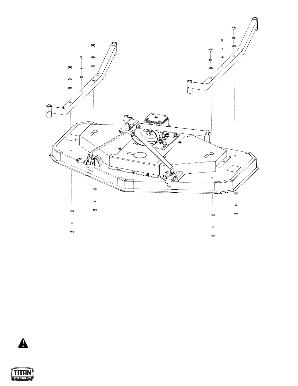
FIGURE 9: Installing Long, Short Pivot Bar, Upper Lift Bracket and Fittings
Step2: Installing Wheel Frame and Fittings
Remove the packaging of wheel frame and fittings. Assemble 2pcs
of wheel frames on the mower deck body.
Parts: 4pcs of Bolts M16x95, 8pcs of plain washers 16, 4pcs of spring washers 16, 4pcs of nuts M16,2pcs of bolt
M8x16, 2pcs of plain washers 8 and 2pcs of large plain washers 8.
Tighten nut and bolt completely.
WARNING
Raise the mower deck body to ensure that the wheel frame can be installed with enough
height.
14
FIGURE 10: Installing Wheel Frame and Fittings
Step3: Installing wheel bracket assembly and Fittings
Remove the packaging of wheel bracket assembly and fittings. Assemble wheel bracket
assemblies on wheel frame as well as spacers.
Through the combination of spacers with different height to get the mowing height you need.
Parts: 4pcs of wheel bracket assemblies. Use safety lock
pin to hold wheel bracket.
WARNING

15
Make sure all wheel height adjustments are same, otherwise it will lead to uneven mowing.
FIGURE 11: Installing wheel Bracket and Fittings
Step4: Installing discharge guide and Fittings
Remove the packaging of discharge guide and fittings.
Assemble discharge guide on mower deck body using included fittings.
Parts: 4pcs of bolts M10x25, 3pcs of plain washers 10, 7pcs of large plain washer 10 and 5pcs oflocknuts M10.
Tighten all locknuts and bolts completely.
FIGURE 12: Installing Discharge Guide and Fittings

16
PARTS DIAGRAM / EXPLODED VIEW

17

18

19

20
This manual suits for next models
5
Table of contents
Other Titan Attachments Lawn Mower manuals


Popular Lawn Mower manuals by other brands

Pattfield Ergo Tools
Pattfield Ergo Tools PE-ARM 36 Li Translation of the original instructions

Snapper
Snapper LT145H33DBV Safety instructions & operator's manual

Stiga
Stiga Combi 336c Operator's manual

Simplicity
Simplicity SNAPPER 250 Z Operator's manual

MTD
MTD 138-664-401 owner's guide

Victory
Victory FMHDH Series Operator's manual


