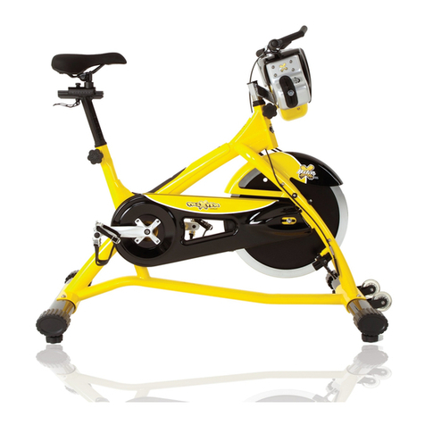
Titan Fitness FANBK User manual

TITAN FITNESS®FAN BIKE
FANBK
402604
Operator’s Manual
Read the Operator’s Manual entirely. When you see this
symbol, the subsequent instructions and warnings are serious
follow without exception. Your life and the lives of others
depend on it!
Cover photo may show optional equipment not supplied with
standard unit. For an Operator’s Manual and Decal Kit in French or
Spanish Language, please see

2
COMPONENTS AS SHIPPED

3
ASSEMBLY PARTS LIST
KEY BOX DESCRIPTION QTY
1 1 MAIN FRAME 1
2 1 FRONT STABILIZER 1
3 1 REAR STABILIZER 1
4 1 CONSOLE MAST 1
5 1 SEAT POST ASSEMBLY 1
6 1 SEAT SLIDE ASSEMBLY 1
8 1 LEFT HANDLEBAR ASSEMBLY 1
9 1 RIGHT HANDLEBAR ASSEMBLY 1
30 1 TURF TIRE AXLE 1
38 1 LEFT PEDAL 1
39 1 RIGHT PEDAL 1
40 1 WATER BOTTLE HOLDER KIT 1
41 1 SEAT PAD 1
56 1 POP PIN 2
56 1 LEVELING FOOT 4
57 1 TURF TIRE 2
59 1 CONSOLE 1

4
ASSEMBLY INSTRUCTIONS
STEP 1
A. Remove the four Allen Bolts (76) and two
Gray Base Tubes (10) and discard in the trash
(for shipping protection only).
STEP 2
A. Install the four Leveling Feet (56) on the
Front Stabilizer (2) and the Rear Stabilizer
(C3). Twist into the four outermost holes.
B. Install the Front Stabilizer (2) and the
Rear Stabilizer (3) on Main Frame (1),
using Allen Bolt M10*35 (81), Spring
Washer (87), and Flat Washer (91).
C. Adjust the four Leveling Feet (56) to
ensure that the Main Frame (1) is level,
then tighten the Thin Nut (97) firmly to
the Front Stabilizer (2) and Rear Stabilizer
(3).

5
ASSEMBLY INSTRUCTIONS
STEP 3
A. Install the Turf Tire Axle (30) on the
Front Stabilizer (2), using the Allen
Bolt M10*35 (81) and
Flat Washer (91).
B. Install the two Turf Tires (57) on the
Turf Tire Axle (30), using Big Washer
(92) and Allen Bolt M10*35 (81).
STEP 4
A. Insert the Seat Mast (5) into the Main Frame (1)
and secure using the Pop Pin (42). To properly
secure the pop pin, once the seat is at the
desired height, firmly tighten the knob.
B. Insert the Seat Slide Assembly (6) into the Seat
Mast (5). Slide all the way to the back.
C. Screw in the Allen Bolt M6*15 (73) to the lower
back of the Seat Slide Assembly (6). Then insert
the Pop-Pin Knob (42).
D. Attach the Seat Pad (41) onto the Seat Slide
Assembly (6), using the Allen Bolt M6*15 (73)
and Big Washer (27). The Collar goes onto the
knurling to keep from rotating.
E. Adjust the Seat Pad (41), then firmly tighten the
nuts on both side of Seat Pad (41).

6
ASSEMBLY INSTRUCTIONS
STEP 5
A. Remove the Rubber Grommet (55), expose the Sensor Plug (60), then reinstall Rubber Grommet (55).
B. Carefully connect the Sensor Plug (60) to the Console Plug (61).
C. Install the Console Mast (4) on the Main Frame (1) using Allen Bolt M8*25 (75), Spring Washer (86), and
Flat Washer (90). DO NOT TIGHTEN THE BOLTS UNTIL THE END OF STEP D.
D. Attach Water Bottle Holder (40) onto Console Mast (4), using Flat Washers (89),
and Allen Bolts M5*15 (78).

7
ASSEMBLY INSTRUCTIONS
STEP 6
A. Install the Left Handlebar (8) by partially threading the Footrest (33) onto the Main Frame (1). Attach
Linkage Arm (7) to the pre-installed Allen Bolt M8*45 (79) on the lower portion of the Left Handlebar
using the M8 Locking Nut (96). Finish tightening Footrest (33) to Main Frame (1).
B. Install the Right Handlebar (9) by partially threading the Footrest (33) onto the Main Frame. Attach
Linkage Arm (7) to the pre-installed Allen Bolt M8*45 (79) using the M8 Locking Nut (96). Finish
tightening Footrest (33) to Main Frame (1).

8
ASSEMBLY INSTRUCTIONS
STEP 7
A. Adjust the handles to a parallel position.
B. Remove the pre-existing screws (Button Head Screw M6*20 (72) from the back of the console and pull
the tab for the batteries. The console will turn on once you remove the tab.
C. Connect the Console Plug (61) with the back of the Console (59).
D. Install the Console (59) onto the Console Mast (4) by using the Button Head Screw M6*20 (72).
E. Adjust the Console Mast (4) to ensure it is evenly spaced and square to the Main Frame (1) and tighten
the two Console Mast bolts to the Main Frame (1)

9
ASSEMBLY INSTRUCTIONS
STEP 8
A. Install the Left Pedal (38) onto the Left Crank (34), turning the pedal counterclockwise.
B. Install the Right Pedal (39) onto the Right Crank (35), turning the pedal clockwise.

10
CONSOLE OVERVIEW
Interval Display Panel
Time Display Panel
Calories Display Panel
Heart Rate Display Panel
Distance Display Panel
Watts, Speed & RPM
Metrics Display
Control Keypad
Quick Launch Program Keys
Sliding Tray Holder with
Grip Pad

11
INTERVAL DISPLAY PANEL
The Interval Display Panel shows all display details for the Interval 20/10, Interval
10/20, and Interval Custom programs.
The upper banner signals which interval program is running as well as when the
running interval is a Work or Rest period.
The Total Time display counts the total program run time while the large numeric display counts the Work or Rest segment
time.
The 88/88 Display shows the current interval and the total number of intervals in the program.
TARGET TIME, DISTANCE AND CALORIES DISPLAY PANEL
The Target Display Panel tracks Time, Distance, and Calories during all programs. A
banner across the top signifies if one of the three Target programs is running.
The Time display alternates between the remaining and elapsed values throughout the
program.
Total Distance is displayed in miles. The Calories display tracks the number of calories
burned during the workout.
WATTS / SPEED / RPM DISPLAY
Watts, Speed, and RPM is displayed during all programs.
Watts are a measure of energy generation and are used to track the amount of work
generated at any given time during a workout.
The Speed display posts a value that simulates riding a standard bicycle and is derived from RPM pedal speed. The value is
given in miles-per-hour. RPM or revolutions-per-minute is the speed at which the pedal cranks are spinning.
HEART RATE DISPLAY PANEL
This panel requires a wireless heart rate chest strap (not included) to display
the user’s heart rate.
When the wireless monitor detects a signal, the user’s heart rate is displayed in
the three-digit BPM (beats-per-minute) field, and the Heart icon flashes.
Conversely, when a signal is not detected, the no signal banner posts and the
heart icon does not light.
When the target heart rate program runs, the console helps the user maintain a BPM range to build cardiovascular
endurance. The upper and lower values of the target range display next to the 65% of Max HR and 80% of Max HR
banners, and the Decrease Speed or Increase Speed banners flash to signal that increased pedal speed is needed to
bring the heart rate into the desired range. When the user’s heart rate is within the target range, the Target Heart
Rate Achieved banner posts.

12
CONSOLE KEYS
CONSOLE SET-UP / FEATURES
BATTERY INSTALLATION
The Titan® Fan Bike console operates on four (4) AA batteries. The battery compartment is on the
backside of the console.
SLEEP MODE
After a period of inactivity, the console enters the power-saving Sleep Mode. The display switches off,
but all previously entered data is saved. To launch the Ready Mode, rotate the pedals or press any
button on the console.
If the speed sensor is too close to the speed sensor magnet, the console will NOT go into Sleep Mode
and will beep every 10 minutes to let you know the console is not in sleep mode. To stop the beeping
STOP KEY
Use the STOP key to end a program
ENTER KEY
The enter key confirms a value to
be entered while adjusting a program
LEFT/RIGHT ARROW KEYS
The “-“/”+” Arrow keys allow the
user to increase and decrease
console values.
PROGRAM QUICK KEYS
The Program Quick keys launch
the associated programs
immediately.
START KEY
The START key launches a
program and restarts a
paused program

13
move the pedals so the speed sensor is away from the speed sensor magnet. This will allow the bike
to go into Sleep Mode and eliminate any battery drain.
READY MODE
The Ready Mode is designed to notify the user that the console is powered on and ready to begin a
program. The Ready Mode is five (5) minutes in length. If no other activity occurs before the Ready
Mode period has elapsed, the console will re-enter the Sleep Mode.
RESET PROCESS
To reset all saved settings, press and hold the STOP key for three seconds.
PAUSE MODE
While any program is running, pressing the START key launches the Pause Mode. The onboard beeper
sounds every three (3) seconds to serve as a reminder, and the display flashes on and off. If no further
input is made, the Pause Mode ends, and the console enters the Ready Mode. To exit the Pause Mode
and continue the currently running program, press the START key. To quit the paused program at any
time, press the STOP key three (3) seconds to launch the Ready Mode.
ELAPSED TIME AND REMAINING TIME SWITCHING
While running a program, the Total Time and Segment Time values switch between elapsed and
remaining.
PROGRAM OPERATIONS
QUICK LAUNCH (NO PROGRAM)
Press the ENTER key; the age is automatically launched at 30 years old. Press the START key and start
pedaling. Console will count Time, Distance, and Calories; and display momentary Watts, Speed, and
RPM. If you want to change age, before pressing the Start button, use the arrow buttons to scroll up
or down to age, press Enter, then press Start.
PROGRAM QUICK LAUNCH
The Quick Launch mode can change the program with the touch of a single key. At any time during
the workout, press a Program Quick Key to launch the associated program immediately.
WORKOUT SUMMARY
The Titan® Fan Bike console provides a brief Workout Summary immediately following the completion
of the workout session. Press the STOP button, and all workout metrics will be displayed for the
workout:
•Total Time
•Total Distance
•Total Calories
•Average Watts
•High/Low Speed
•High/Low RPM

14
•Max/65%/85% Heart Rate (If Compatible Heart Rate Monitor Is Used- Not Included)
INTERVAL 20/10 AND INTERVAL 10/20 PROGRAMS
The Interval 20/10 and Interval 10/20 programs offer the user a series of eight (8) high-intensity
workout intervals with preset time segments. This training protocol is commonly known as High
Intensity Interval Training (H.I.I.T.). The program automatically signals the start of each work and
rest interval.
INTERVAL 20/10 PROGRAM
•
Number of Intervals: 8
•
Work Interval Length: 20 seconds
•
Rest Interval Length: 10 seconds
•
Interval Time: 3 minutes
INTERVAL 10/20 PROGRAM
•
Number of Intervals: 8
•
Work Interval Length: 10 seconds
•
Rest Interval Length: 20 seconds
•
Interval Time: 3 minutes
LAUNCH: To start the Interval 20/10 or Interval 10/20 programs, press the appropriate program key.
RUN: The time counts down from three minutes to signal the start of each work interval.
END: The program runs until the last of the rest segments end. To end the program at any time,
press the STOP key. The Workout Summary launches and posts a record of the workout data.
INTERVAL CUSTOM PROGRAM
The Interval Custom program is like the Interval 20/10 Program, except the user can set the length of the
work and rest intervals and the total number of intervals.
LAUNCH: Press the Interval Custom program key.
SETUP: When running the Interval Custom program for the first time (or after the console has been reset),
the user is required to enter the total number of intervals. Adjust the displayed value by pressing the “+” or “-
” keys, followed by the ENTER key to confirm. The default work interval is then displayed. Adjust the display
value with the “+” or “-” keys. Confirm by pressing ENTER. The default rest interval will display. Adjust the
value and confirm by pressing ENTER.
RUN: The timer counts down from three minutes to signal the start of each work interval, and the program
runs immediately.
END: The program ends automatically when all interval segments have run. To complete the program at any
time, press the STOP key. The Workout Summary launches and displays a record of the workout data.

15
TARGET TIME, TARGET DISTANCE, AND TARGET CALORIES PROGRAMS
The Target Time, Target Distance, and Target Calories programs each operate identically. In each program, the user can
define a set value, and the program will continue until that goal has been achieved.
LAUNCH: From the Off/ Reset position, press Enter key to confirm age 30. Press the desired target key
– Target Time, Target Distance, or Target Calories. Use the arrow keys to get to desired value and
press start. The console will count till your programmed goal is achieved and signal completion with a
beep.
SETUP: When running the Target programs for the first time (or after the console has been reset), the
display flashes with the default value. Adjust the displayed value by pressing the “+” or “-” keys,
followed by the ENTER key to confirm. The program begins automatically.
RUN: The display fields light and begin to track the progress of the user. If the Target Time program
has been selected, the time target begins to count down. If the Target Distance program is running,
the console tracks the progress toward that goal. When the Target Calories program has been
selected, the console tracks calories.
END: The program ends automatically when the selected target is achieved. To complete the program
at any time, press the STOP key. The Workout Summary launches and displays a record of the
workout data.
TARGET HEART RATE PROGRAM
The Titan® Fan Bike Target Heart Rate Program offers users the ability to target a BPM (beats-per-
minute range) for maximum cardiovascular training. The Heart Rate Program requires the use of a
Polar (or compatible) Chest Heart Rate Monitor (not included). With the user's age, the console
automatically calculates the Maximum Heart Rate and the optimized training range (65% of Max BPM
to 80% of Max 8 BPM).
LAUNCH: Press the Target Heart Rate program key to launch the program.
SETUP: When running the Target HR programs for the first time (or after the console has been reset),
the AGE BANNER and default age value will flash. Adjust the user's age by pressing the "+" or "-" keys,
followed by the ENTER key to confirm. The program will begin automatically.
RUN: The display fields will light and begin to track the progress of the user.
If the user's heart rate is below the calculated 65% max HR range, the SPEED UP banner flashes to
indicate that more effort is required to maintain the optimal heart rate.
If the user's heart rate exceeds 80% of the calculated maximum heart rate, the Beeper will go off to
work too hard.
END: The Target Heart Rate program runs until ended manually by the user. To complete the program
at any time, press the STOP key. The Workout Summary is displayed.
USING THE WIRELESS HEART RATE RECEIVER
In general, a Wireless Heart Rate Chest Strap (not included) is the most accurate method of detecting
and monitoring a heart rate signal. Occasionally, certain factors can negatively affect the precise

16
transmission of the heart rate signal. Wi-Fi networks, cordless telephones, and large electrical
appliances may degrade or corrupt the signal so that the rate appears erratic or impossibly high. The
only remedy for such a symptom is to isolate the unit from potential disturbances. Additionally, a
person's body chemistry or lack of sweat can prevent the chest strap from providing a strong or
accurate heart rate signal. The TITAN® Fan Bike is equipped with a wireless heart rate receiver to
detect an HR signal being transmitted by a wireless chest strap (not included).
For the console to detect and display your heart rate wirelessly, four (4) conditions must be present:
•A compatible heart rate chest strap transmitter must be functioning and worn. For the proper
function of the chest strap, please refer to the manufacturer's instructions. Non-coded transmitters
such as the Polar Heart Rate Monitors are examples of wireless chest straps that are compatible with
this unit.
•The unit must be turned on.
•A workout program must be running.
•The user is within three (3) feet of the console.
CALCULATED MAXIMUM HEART RATE AND TARGET TRAINING ZONE
Your target heart rate is calculated from your age. It is essential to work within a safe and productive
zone. If the exercise intensity is too low or too high, only modest gains are achieved in strength and
cardiovascular fitness. Conversely, if the workout intensity is too high, injury or fatigue may slow the
progression of exercise goals as the body needs time to recover.
NOTE: It is most useful to train at a heart rate between 65% and 80% of your maximum heart rate.
Maximum heart rate is calculated as a percentage of your maximum heart rate (estimated as 220
BPM minus your age).
To calculate your maximum heart rate and find the appropriate target training zone, the console uses
the following formulas. Example shows 35-year-old user:
•220 - 35 = 185 BPM (220 - Age= Calculated Maximum Heart Rate in BPM)
•0.65 x 185 = 120 BPM (65% of 185 BPM [Calculated Maximum Heart Rate] = 120 BPM)
•0.80 x 185 = 148 BPM (80% of 185 BPM [Calculated Maximum Heart Rate] = 148 BPM)
Based on these calculations, this user's recommended heart rate training zone would be between 120
BPM and 148 BPM. It will be displayed on the console when using Target Heart Rate with a
compatible heart rate chest strap transmitter (not included).

17
FULL PARTS LIST / EXPLODED VIEW
KEY BOX DESCRIPTION QTY KEY BOX DESCRIPTION QTY
(1) 1
MAIN FRAME
1
(50) 1
SEAT SLIDE RAIL SLEEVE
2
(2) 1
FRONT STABILIZER
1
(51) 1
SPEED SENSOR MAGNET AND PLATE
1
(3) 1
REAR STABILIZER
1
(52) 1
SPEED SENSOR MAGNET SEAT
1
(4) 1
CONSOLE MAST
1
(53) 1
SENSOR BRACKET
1
(5) 1
SEAT POST
1
(54) 1
PVC CABLE PLUG
1
(6) 1
SEAT SLIDE RAIL
1
(55) 1
RUBBER GROMMET
1
(7) 1
LINKAGE ARM
2
(56) 1
LEVELING FOOT
4
(8) 1
LEFT HANDLEBAR
1
(57) 1
TURF TIRE
2
(9) 1
RIGHT HANDLEBAR
1
(58) 1
CELL PHONE HOLDER
1
(10) 1 GRAY BASE TUBE (FOR SHIPPING
ONLY) ( NO USE FOR ASSEMBLY)
2 (59) 1 CONSOLE 1
(11) 1
BELL CRANK
1
(60) 1
SENSOR PLUG
1
(12) 1
CHAIN WHEEL
1
(61) 1
CONSOLE PLUG
1
(13) 1
FRONT CHAINGUARD
1
(62) 1
RIVET Φ15*12
6
(14) 1 CHAIN GUARD 1 (63) 1 6003ZZ BALL BEARING 2
(15) 1
REAR CHAINGUARD
1
(64) 1
6003ZZ BALL BEARING
4

18
FULL PARTS LIST / EXPLODED VIEW
KEY
BOX
DESCRIPTION
QTY
KEY
BOX
DESCRIPTION
QTY
(16) 1
BIG L BRACKET FOR CHAINGUARD
1
(65) 1
6202RS BALL BEARING
2
(17) 1
FAN WHEEL ASSEMBLY
1
(66) 1
KNUCKLE BEARING
2
(18) 1
MID HUB ASSEMBLY
1
(67) 1
SELF TAPPING SCREW 4.8*20
2
(19) 1
CHAIN WHEEL
1
(68) 1
SELF TAPPING SCREW 4.8*15
3
(20) 1
RIGHT FAN CAGE
1
(69) 1
BUTTON HEAD SCREW M5*6
15
(21) 1
LEFT FAN CAGE
1
(70) 1
BUTTON HEAD SCREW M5*30
1
(22) 1
SPEED SENSOR PLATE CLIP
3
(71) 1
BUTTON HEAD SCREW M5*10
1
(23) 1
FAN CAGE COVER
1
(72) 1
BUTTON HEAD SCREW M5*15
4
(24) 1 SMALL L BRACKET FOR
CHAINGUARD
1 (73) 1 ALLEN BOLT M6*15 2
(25) 1
POSITIONING PLATE
1
(74) 1
ALLEN BOLT M6*12
1
(26) 1
BLADE
6
(75) 1
ALLEN BOLT M8*25
2
(27) 1 BIG WASHER 1 (76) 1 ALLEN BOLT M10*15 (FOR SHIPPING
ONLY)
4
(28) 1
FOOT PEG
2
(77) 1
ALLEN BOLT M6*25
3
(29) 1
PEDAL SHAFT
1
(78) 1
ALLEN BOLT M5*15
2
(30) 1
TURF TIRE AXLE
1
(79) 1
ALLEN BOLT M8*45
2
(31) 1
BEARING SLEEVE
2
(80) 1
TUBULAR RIVET M8
2
(32) 1
BUSHING
2
(81) 1
ALLEN BOLT M10*35
8
(33) 1
FOOTREST
2
(82) 1
CLIP Φ17
2
(34) 1
LEFT CRANK
1
(83) 1
CLIP Φ22
2
(35) 1
RIGHT CRANK
1
(84) 1
CLIP Φ35*1.2
2
(36) 1
SHORT CHAIN
1
(85) 1
WAVE WASHER Φ17*Φ19*0.5
9
(37) 1
LONG CHAIN
1
(86) 1
SPRING WASHER Φ8
2
(38) 1
LEFT PEDAL
1
(87) 1
SPRING WASHER Φ10
4
(39) 1
RIGHT PEDAL
1
(88) 1
FLAT WASHER M5(Φ5.5*Φ10*1)
2
(40) 1
WATER BOTTLE HOLDER KIT
1
(89) 1
FLAT WASHER M5(Φ5.5*Φ10*1)
2
(41) 1
SEAT PAD
1
(90) 1
FLAT WASHER Φ9*Φ16*1.6
2
(42) 1
POP PIN
2
(91) 1
FLAT WASHER Φ11*Φ20*2
10
(43) 1
PVC TUBE
6
(92) 1
BIG WASHER Φ11*Φ34*3
2
(44) 1
PVC HANDLE GRIP
2
(93) 1
NYLON NUT M5
1
(45) 1
PP WIND SHIELD
1
(94) 1
NYLON NUT M6
3
(46) 1
PLUG
1
(95) 1
THIN NUT M8
2
(47) 1
PLUG
1
(96) 1
LOCK NUT M8
2
(48) 1
END CAP FOR CRANK
4
(97) 1
THIN NUT M10
4

19
ACKNOWLEDGEMENT OF RISK AND RELEASE OF LIABILITY
The use of any equipment, including this one, involves the potential risk of injury. Apart from any warranty
claim that might be presented for a claimed defect in material or workmanship of the product, you accept
and assume full responsibility for any and all injuries, damages (both economic and non-economic), and
losses of any type, which may occur, and you fully and forever release and discharge Titan, its insurers,
employees, officers, directors, associates, and agents from any and all claims, demands, damages,
rights of action, or causes of action, present or future, whether the same be known or unknown,
anticipated, or unanticipated, resulting from or arising out of the use of said equipment.
This equipment must be used with care by capable and competent individuals under supervision,
WARNING
Heavy object. Use lifting aids and
proper lifting techniques when moving.
Choking hazard. Small parts –
Please exercise caution if small
children or pets are present.
Sharp objects may be involved.
Use precaution and protection.
TITAN LIMITED WARRANTY: TERMS, EXCLUSIONS AND LIMITATIONS OF REMEDIES
This product comes with a one (1) year limited warranty that can be found at
www.titan.fitness/warranty.html Please review the same for all details regarding the
Titan Limited Warranty.
THE TITAN LIMITED WARRANTY FOUND AT WWW.TITAN.FITNESS/WARRANTY IS EXCLUSIVE AND IS IN
LIEU OF ALL OTHER WARRANTIES, EXPRESS OR IMPLIED, INCLUDING ANY IMPLIED WARRANTY OF
MERCHANTABILITY AND/OR FITNESS FOR A PARTICULAR PURPOSE, EACH OF WHICH IS HEREBY
DISCLAIMED.
(49) 1
PLUG
8
(98) 1
FLANGE NUT M10*1.25
4

NEED HELP? CONTACT US FIRST.
1-888-410-1503
info@titan.fitness
www.titan.fitness
© 2021 Titan Brands
This manual suits for next models
1
Table of contents
Popular Exercise Bike manuals by other brands

Sunny Health & Fitness
Sunny Health & Fitness SF-B121021 user manual

Monark
Monark 827E instruction manual

Stamina
Stamina 1310 owner's manual

American Fitness
American Fitness SPR-BK1072A owner's manual

Cateye
Cateye CS-1000 (CYCLO SIMULATOR) Service manual

BH FITNESS
BH FITNESS H9158H Instructions for assembly and use


